Table of Contents
Advertisement
Quick Links
Advertisement
Table of Contents
Troubleshooting

Related Manuals for Tonghui TH2617


Summary of Contents for Tonghui TH2617
- Page 1 OPERATION MANUAL TH2617 PRECISON LCR METER...
-
Page 2: Table Of Contents
Contents 1 Chapter I Generals ..............2 1.1 Introduction ................. 2 1.2 Technical Specifications ............... 3 1.2.1 Measurement Parameters ............. 3 1.2.2 Measurement Terminals .............. 3 1.2.3 Test Frequency ..............3 1.2.4 Display Range ..............3 1.2.5 Measurement Accuracy............... 3 1.2.6 Measurement Level .............. - Page 3 2.4.2 Equivalent Model ..............20 2.4.3 D Displayed in PPM Mode ............22 2.4.4 Volume and State of Alarm............22 2.4.5 Correction ................ 22 2.5 Sorting Function..............24 2.5.1 Introduction of Sorting .............. 24 2.5.2 Limits and Nominal Setup............24 2.5.3 Example of Sorting ..............
- Page 4 DANGER The highest external DC bias voltage is 100V. When external dc bias voltage is applied, the high voltage exists between the test terminals of the meter. Special care should be taken when carrying out test to avoided injury of human body caused by electrical shock. When making test with external bias voltage applied, please do not contact directly or plug in/draw out the component under test on the test fixture or test cable because leads of the tested component are of high voltage.
-
Page 5: Chapter I Generals
Meanwhile, the interfaces of Handler and RS-232c make it possible for the instrument to work with automatic sorting machine and communicate with computer. The measurement conditions and values can be printed directly through the printer interface. TH2617 really provides customers an instrument of high performances but low price. -
Page 6: Technical Specifications
C and R have different values. The relations between the two equivalent circuits are discussed in section 2.3.4. TH2617 has the following parameters: C/D, R/D, C/C, R/R, and D/D. C/D and R/D can only be selected in the status of single-frequency. And in the status of double-frequency, the first parameter is result of Frequency 1. -
Page 7: Measurement Level
D: ±0.0003 (1+Z ) (1+D ) (1+k )+0.0002; Notes: 1. D is absolute deviations and others are percent deviations; 2. Those with subscript mean measurement values of the parameters, those with subscript mean maximum values and mean minimum values; 3. k is the speed factor, k is the level factor and k is the frequency factor;... -
Page 8: Measurement Speed
Here f is measurement frequency with the unit of kHz; When Range = 0, k = 0.25; When Range = 1, k = 0.025; When Range = 2, 3 or 4, k = 0.005. Due to the output impedance of the signal source, the actual level applied upon the component under test may be different from the set value. -
Page 9: Measurement Mode
equivalent circuit models. Measurement Mode 1.3.4 Continuous: the instrument continuously repeats measurements and displays the values after each measurement; Single: usually the instrument is in the wait for trigger state, the instrument performs a single measurement every time a “Start” signal from the keyboard or from the interface is received. -
Page 10: Handler Interface
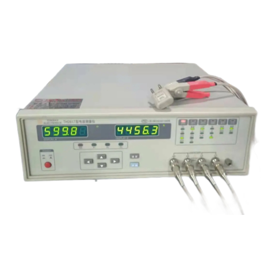
Terminal is tied to the instrument’s chassis, and it is connected with the protective earth ground of power supply. Test Terminals Trade Mark & Model TONGHUI, TH2617 Capacitance Meter Functions and measurement conditions of the instrument can be Keyboard selected and controlled by the 6-button keyboard. -
Page 12: Description Of The Rear Panel
Description of the Rear Panel 1.4.2 Description of the rear panel: Name Description of Function Provide serial interface between the instrument and peripheral RS-232 Serial equipments. Parameters, instructions and measurement results Interface (9-Pin) can be sent and received through the interface. By using the Handler Interface, the instrument can easily be Handler Interface combined with a component handler, and a system controller to... -
Page 14: Chapter Ⅱ Operation Instruction
Figure 2-1 Keyboard of TH2617 Figure 2-2 Measurement States of TH2617 TH2617 has only six keys shown as Figure 2-1. These keys are used to select controls and set parameters. The keys have different functions in different conditions. There are three main menus. -
Page 15: Conversion Of Menus
Third Menu: The instrument enters the third menu by pressing the SET key once again when the instrument is in the second menu. You should press the SET key twice if the instrument is in the first menu. All the limits and nominal parameters can be inputted in this menu. If you press the SET key again in the third menu, the instrument will return to the measuring state (or the First Menu). -
Page 16: Functions Setup In The First Menu
from one menu to another menu are described as follows: The instrument is in the First Menu when it is switched on. You can set the functions in this menu. If you want to set the functions in other menus, you should change to the corresponding menu first. -
Page 17: Measurement Parameter
ON, which means the state is selected. Measurement Parameter 2.3.1 Parameters to be measured by TH2617 are as follows: Cs, Cp, ESR, EPR. Units of all parameters are as follows: C: pF, nF and μ... - Page 18 Table 2-1 Units and resolutions for different ranges Deviation Measurement 2.3.2.2 TH2617 provides two types of deviation measurements. They are absolute deviation measurement and percent deviation measurement. Measurement speed will be reduced because more time will be used to calculate the deviation.
-
Page 19: Measurement Level
TH2617 has three measurement levels for choice: 1V 0.3V 0.1V An inductor's inductance value may differ widely depending on the current through the inductor due to the permeability of its core material. Measurement Speed 2.3.4 TH2617 provides three measurement speeds: fast, medium and slow. -
Page 20: Measurement Range
We can use the averaging function to acquire the more stable and accurate measurement value, but the measurement speed will be decreased. The averaging rate of TH2617 can be programmed from 1 to 99. The default value is 1, when the instrument is switched on. -
Page 21: Cont And Single Mode
If the impedance of the device under test is out of the effective measuring range of the held range, TH2617’s measurement accuracy does not meet its specification. So make sure that the optimum range is selected when using the range hold function. -
Page 22: Functions In The Second Menu
the Handler interface or by the instruction via the RS-232C interface. Functions in the Second Menu All functions in the second menu are shown as follows in Table 2-4. Functions States Name Display B Name Display A 100 Hz 0.1000 120 Hz 0.1201 Measurement... -
Page 23: Set The Test Frequency
The resistor and reactor in both series and parallel models can be measured by TH2617. The values in the two different equivalent circuits can be converted to each other mathematically. The values are different due to the quality factor Q (or the dissipation factor D). - Page 24 π π Table 2-5 Relations between the series and the parallel circuits Where: C: Capacitance f: Frequency R: Resistance D: Dissipation Factor Subscript s means series model and subscript p means parallel model. Form the above table, we can see that the parameters have relations with D , and the value of D will directly affect the values of the parameters.
-
Page 25: D Displayed In Ppm Mode
In order to maintain high measurement accuracy, SHORT and LOAD corrections for correcting the stray admittance, the residual impedance, and the other errors can be performed. OPEN correction and SHORT correction are provided by TH2617. When TH2617 performs OPEN/SHORT correction, all the frequency points are corrected. - Page 26 When test speed or test level is changed, another OPEN/SHORT correction should be performed. The correction data for last time is rewritten after the correction is finished. All correction data is stored in a non-volatile memory inside the instrument, so you don’t have to correction the instrument again when the instrument is switched on.
-
Page 27: Sorting Function
P1 to P3. TH2617 has three kinds of sorting modes, Direct mode (DIR), Absolute deviation mode (ABS) and Percent deviation mode (PER). There is no relations between the sorting mode and the display mode (Direct, △... - Page 28 value is stored. Note: X is the measurement value of main parameter. Figure 2-6A Flow Chart of Sorting in the Status of Single-frequency There are two methods for specifying primary parameter limits. In both methods the high limit must be greater than the low limit for a certain pairs of limits. Tolerance Mode: The tolerance mode specifies bin limits by the deviation from the specified nominal value.
- Page 29 Figure 2-7 Tolerance Mode Sequential Mode : The sequential mode specifies bin limits as the actual measurement value. The limits must be set in order from the smallest value to the largest value. There can be openings and duplications between the bin limits. (Refer to Figure 2-8.) Figure 2-8 Sequential Modes The nominal value is set according to the selection of measurement parameters.
- Page 30 Symbol Description Down F1P1 High limit of bin P1 at F 1 F1P1 Low limit of bin P1 at F 1 F1P2 High limit of bin P2 at F 1 F1P2 Low limit of bin P2 at F 1 F1P3 High limit of bin P3 at F 1 F1P3 Low limit of bin P3 at F 1...
-
Page 31: Example Of Sorting
A or B. Handler Interface By using the handler interface, TH2617 can easily be combined with a component handler, and a system controller to fully automate component testing, sorting, and quality control data processing. External “START” signal is received for triggering the instrument to start measurement, while WAIT and EOC signals are output. -
Page 32: Operation
measurement, but the component handler must keep still before EOC is effective. Sorting result of each bin is outputted by an open-collector gate. Handler interface locates on the rear panel of the instrument. Operation 2.6.1 The Handler interface works only when the following three conditions are met: 1. -
Page 33: Connector Of Handler Interface
Table 2-8 HANDLER Interface Pin Assignments Standard Printer Interface TH2617 provides a standard parallel printer interface which can be connected to any printer which has the standard printer interface. Function setup, comparison limits, measurement value, and comparison results can be printed. -
Page 34: Print Format
Printer interface connector pin assignments are as follows: Figure 2-11 Pin Assignments of Printer Interface Pin assignments for printer interface: Pin No. Name Direction Function The signal tells the printer that data on the bus is effective and Output STROBE ready to be read. -
Page 35: Serial Interface(Rs-232C)
1. Measurement parameter (PARAM.); 2. Measurement frequency (FREQU.); 3. Measurement level (LEVEL); 4. Measurement speed (SPEED); 5. Averaging rate (AVERA.); 6. Equivalent circuit (EQUIV.); 7. Range mode (RANGE); 8. Measurement mode (MODE); 9. Display mode (DISP.); 10. D,Q in PPM display mode (DQ-PPM); 11. - Page 36 8V and the maximum transmission distance is 15m. The data format is as follows: Figure 2-12 Data Format TH2617 serial interface adopts direct communication. Only three signal wires are used in serial communication, TXD, RXD and GND. A 9-pin standard connector is used, as shown in Figure 2-13.
- Page 37 parameters Resistance/dissipation Capacitance/capacitance There is not the mode status Resistance/resistance single-frequency, Dissipation/dissipation D: direct A: absolute deviation Display mode D, A, P, V P: percent deviation V: V/I display Level L, M, H L: 0.1V M: 0.3V H: 0.1V Test speed S, M, F S: slow M: medium...
- Page 38 Table 2-10: Format of Output Information Commands for serial interface are shown as in Table 2-11(computer TH2617) In the following table, each command can only be sent alone, and you are not allowed to send more than two commands at a time. Each command starts with 02H and 0DH and ends with 3FH.
- Page 39 Measurement parameters: R-D Measurement parameters: C-C invalid in the status Measurement parameters: R-R single-frequency Measurement parameters: D-D Display mode of direct Display mode of △ % Display mode of △ Display mode of V/I Measurement level: 1.0V Measurement level: 0.3V Measurement level: 0.1V Test speed: fast speed Test speed: medium speed...
- Page 40 Alarm bin: NG Alarm bin: P1 Alarm bin: P2 Alarm bin: P3 No-correction: ON No-correction: OFF Serial interface: ON Serial interface: OFF Printer interface: ON Printer interface: OFF Handler interface: ON Handler interface: OFF Sorting: OFF Sorting: percent deviation Sorting: absolute deviation Sorting: direct Open correction Short correction...
-
Page 41: Chapterⅲ Measurement Basics And Troubleshooting
Measurement Basics 3.1.2 1. Turn on the instrument with proper power supply, “ TONGHUI TH2617” will be displayed and shifted in the windows of Display A and B, then the instrument performs the power-on self tests and corresponding information is displayed at the same time, the sequence number is from 99999 to 11111. - Page 42 2. The states of instrument will be initialized after self tests as follows: A. The First Menu (or “measurement” state) Parameter Display Direct Level 1.0V Speed Slow Range Auto Mode Continuous B: The Second Menu Frequency 1kHz Averaging Rate Equivalent circuit Series D,Q PPM Mode Sorting...
-
Page 43: Connection Of Component
Connect the Component 3.2.2 TH2617 has four test terminals and the outer shields of each terminal are connected with the instrument ground, the outer shield can be looked as the fifth terminal. Descriptions of the five terminals are as follows: HD: high drive terminal of current;... - Page 44 Figure 3-11 Stray Capacitance to ground Figure 3-12 Method to Eliminate Influence of Stray Capacitance When component of high impedance (for example small capacitor) is measured, the influence of stray capacitance cannot be ignored. As shown in Figure 3-11, Cd is in parallel with Cx.
-
Page 45: Dc Bias
Here we introduce the way to measure the component with external DC bias. Measurement with DC Bias Voltage TH2617 can be applied with an external DC bias voltage of 100V in maximum. DC bias voltage can be applied according to the circuit described in Figure 3-13. Perform open and short corrections when DC bias voltage is 0V to eliminate the influence of the external circuit, then you can measure the component with the DC bias voltage. - Page 46 4. The high frequency pulses on the pins 29 and 30 of CPU; 5. The display unit. Normally, “ TONGHUI TH2617” is displayed and shifted in the windows of Display A and Display B, then self-tests are performed. Self-tests are stopped when an error occurs.
- Page 47 44444 If A/D converter operates normally, the second information would not be displayed. AD2 means that A/D conversion can be finished for a long time. The failure of A/D converter occurs in many cases. Oscilloscope is often used to check the waves and shapes in the circuit.
-
Page 48: Chapter Ⅳ Packing And Warranty
Chapter Ⅳ Packing and Warranty Packing The contents are listed as follows: Description Quantity 1) Model TH2617 Precision LCR Meter 2) Th26011 Kelvin Test Cables 3) Th26005 Test Fixture 4) Three-Wire Power Cable 5) 1A Fuse 6) Operation Manual 7) Certificate of Quality...
Need help?
Do you have a question about the TH2617 and is the answer not in the manual?
Questions and answers