Table of Contents
Advertisement
Quick Links
Advertisement
Table of Contents

Related Manuals for Tonghui TH2816B


Summary of Contents for Tonghui TH2816B
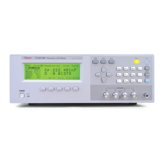
- Page 1 OPERATION MANUAL TH2816B Precision LCR Meter...
-
Page 2: Table Of Contents
Contents Chapter 1 Overview........................5 Product introduction....................5 Operation conditions ....................6 1.2.1 Power requirements....................6 1.2.2 Operation environment....................6 1.2.3 Warm-up time......................6 1.2.4 Notes for usage......................6 Dimension and weight....................7 Safety Summary ......................7 Electromagnetic compatibility ..................7 Chapter 2 Basic Specifications ....................8 Measurement Functions ....................8 2.1.1 Measurement Parameters ..................8 2.1.2 Combinations of Measurement Parameters...............8... - Page 3 4.3.1.2 Test Frequency ......................23 4.3.1.3 Oscillator Level.......................24 4.3.1.4 Measurement Range....................25 4.3.1.5 Measurement Speed ....................26 4.3.1.6 Short Correction ......................26 4.3.1.7 Open Correction ......................27 4.3.1.8 File Management.....................27 4.3.1.9 Useful Tools ......................29 4.3.2 Bin Number Display Page..................30 4.3.2.1 Comparator Function ON/OFF ................31 4.3.2.2 Auxiliary Bin ON/OFF ...................31 4.3.2.3 File Management.....................32...
- Page 4 Command Reference....................59 6.5.1 DISPlay Subsystem....................60 6.5.2 FREQuency Subsystem...................61 6.5.3 VOLTage Subsystem....................62 6.5.4 FUNCtion Subsystem....................63 6.5.5 APERture Subsystem ....................66 6.5.6 TRIGger Subsystem ....................67 6.5.7 FETCh? Subsystem....................68 6.5.8 ABORt Subsystem ....................69 6.5.9 CORRection Subsystem..................69 6.5.10 COMParator Subsystem..................71 6.5.11 Mass MEMory Subsystem ..................76 6.5.12 Common Commands....................77 6.5.13...
-
Page 5: Chapter 1 Overview
Product introduction TH2816B is a precision LCR meter with high accuracy, good stability, and wide measurement range. Controlled by a 16 bits MPU, TH2816B can be used for evaluating LCR components, materials and semiconductor devices over a wide range of frequencies (50 Hz to 200 kHz) and test signal levels (0.01 V to 2.00 V, with 0.01 V... -
Page 6: Operation Conditions
TH2816B has the cooling fan on the rear panel and cooling holes on both sides. High temperature inside will decrease the measurement accuracy, so sufficient... -
Page 7: Dimension And Weight
cooling fans. Don’t frequently turn on and off the instrument, doing so will lead to the loss of the calibrated data and the data saved by users. Dimension and weight Dimensions: 350(W) by 110(H) by 340(D) (mm) Weight: Approximately 4 kg Safety Summary The following general safety precautions must be observed during all phases of operation, service, and repair of this instrument. -
Page 8: Chapter 2 Basic Specifications
Chapter 2 Basic Specifications Measurement Functions 2.1.1 Measurement Parameters Inductance Capacitance Resistance |Z|: Absolute value of impedance Reactance Susceptance Conductance Dissipation factor θ: Phase angle Quality factor 2.1.2 Combinations of Measurement Parameters Main parameters Secondary parameters θ(deg), θ(rad) D, R Suffix “s”... -
Page 9: Ranging
Auto and Manual (Hold/Up/Down), total 9 ranges. 2.1.5 Trigger TH2816B has four trigger modes: INTernal, EXTernal, MANual, and BUS. Except for BUS trigger mode these trigger modes can be set on the front panel. The BUS trigger mode is used when TH2816B is controlled via GPIB. -
Page 10: Delay Time
When the trigger mode is set to BUS trigger mode, TH2816B performs a single measurement every time the *TRG common command is sent to TH2816B via GPIB. The BUS trigger mode cannot be set on the front panel. Send the TRIGger:SOURce BUS command via GPIB or RS232C to set the trigger mode to the BUS trigger mode. -
Page 11: Output Impedance
AUX BIN: Primary parameter is within limits, but whose secondary parameter measurement result is not within limits. If the secondary parameter limits are not set, TH2816B will not compare the secondary parameter. Sorting Modes Absolute deviation mode: absolute deviations are compared with bin limits. -
Page 12: Measurement Results Display
A maximum of 12 sets of instrument control settings can be stored in the internal non-volatile memory. TH2816B will reload the No. 0 file every time when the instrument is turned on. So users can save the control settings in file No. 0 for convenience. -
Page 13: Password
ASCII codes over the bus. 2.3.7.3 HANDLER interface TH2816B can receive the Trigger signal and output the comparison results and list sweep comparison results through the HANDLER interface. Synchronous signal IDX and EOM can be outputted. The output signals are logical low active and opto-isolated. -
Page 14: Chapter 3 Panel And Display Introduction
Chapter 3 Panel and Display Introduction This chapter provides information including a tour of the front panel and display area definition, which will help you to quickly learn how to operate the TH2816B. For more information, please refer to chapter 4. -
Page 15: A Tour Of The Rear Panel
11) Number keys The NUMBER keys are composed of the digits 0 to 9 , a period . , a minus sign - , number keys are used to enter numeric data into the TH2816B. ENTER terminates numeric input data and enters the displayed value in the input ENTER window. -
Page 16: Display Area Definition
BinNo. Disp MeasSetup LimitSetup SystemConfig TH2816B has three MENU keys which are used to switch the LCD display page. HOME MENU key This MENU key always switch to MeasDisplay page. PREV MENU key This MENU key can switch to the previous page sequentially. -
Page 17: Summary Of
MeasDisplay This display page provides the measurement result information, and some control settings are entered from this page. TH2816B measures the DUT from this page, and displays the measurement results in large or normal size characters. This display page is the default display page when TH2816B is turned on. - Page 18 CABLE: 0m Limit Table This display page provides the limit table settings for bin sorting. TH2816B doesn't perform measurement from this page. To see the comparison results, either the BinNo. Disp page or the Bin Count page should be used.
-
Page 19: Chapter 4 Operation
Chapter 4 Operation Basic operation TH2816B's basic operation is described in the following paragraphs. Display the desired display page using the MENU keys and the softkeys. (Refer to Figure 3-1.) Move the CURSOR to the field to be used using the CURSOR keys. The cursor will be an inverse video marker, and the field is an area at which you can set the CURSOR. -
Page 20: Welcome Page
Figure 4-2. Softkey Selection Example Welcome Page Press the power switch to turn on TH2816B, the welcome page will display as shown in Figure 4-3. The name of the instrument with its version will also be displayed. If password function is ON, you must input the correct password to start the instrument. -
Page 21: Detailed Operation
Detailed Operation This Chapter provides information about the function of each page. MeasDisplay BinNo. Disp MeasSetup LimitSetup SystemConfig This Chapter describes the functions on each page in the order of the preceding list. 4.3.1 MeasDisplay Page When you press HOME, the MeasDisplay page will be displayed. On this page, the measurement results are displayed in large characters, and the following measurement controls can be set from this page. -
Page 22: Measurement Function
OpSWP Figure 4-6. Available Softkeys on the MeasDisplay Page 4.3.1.1 Measurement Function TH2816B measures two components of the complex impedance (parameters) at the same time in a measurement cycle. The measurement parameters are listed as follows. Primary Parameters |Z| (absolute value of impedance) -
Page 23: Test Frequency
4.3.1.2 Test Frequency TH2816B operates from 50 Hz to 200 kHz with 37 typical frequency points which can be selected through softkeys, or set through numeric entry keys. Front Panel Operation for Setting the Test Frequency... -
Page 24: Oscillator Level
⇓(--). 4.3.1.3 Oscillator Level TH2816B’s oscillator level can be set as the effective value (RMS value) of a sine wave of the test frequency from TH2816B's internal oscillator. The oscillator level can be set from 0 V to 2.00 V... -
Page 25: Measurement Range
4.3.1.4 Measurement Range TH2816B has nine measurement ranges: 10Ω, 30Ω,100Ω, 300Ω, 1 kΩ, 3 kΩ, 10 kΩ, 30 kΩ, and 100 kΩ. The measurement range is selected according to the DUT's impedance even if measurement parameter is capacitance or inductance. Table 4-2 shows the effective measuring range for each measurement range while in the impedance mode (|Z|, R, X). -
Page 26: Measurement Speed
Use the preceding softkeys to select and set the measurement speed. 4.3.1.6 Short Correction TH2816B's SHORT correction capability corrects for the residual impedance (R, X) in serial with the device under test. Front Panel Operation for the Short Correction There are two procedures: SHORT correction at all frequency points, and SHORT correction at the current test frequency point. -
Page 27: Open Correction
4.3.1.7 Open Correction TH2816B's OPEN correction capability corrects errors due to the stray admittance (G, B) in parallel with the device under test. Front Panel Operation for the Open Correction There are two procedures: OPEN correction at all frequency points, and OPEN correction at the current test frequency point. - Page 28 Low/High Limits for Each Bin Display page format When TH2816B is turned on, TH2816B's auto load function will load the control settings stored in file number 0. If there are no control settings stored in file number 0, the power-on default settings will be used.
-
Page 29: Useful Tools
4.3.1.9 Useful Tools TH2816B displays the measurement data using a six digit floating point display format. The fixed decimal point function is used to display the measurement data using a fixed point display format. This function can also be used to change the number of digits displayed. -
Page 30: Bin Number Display Page
4.3.2 Bin Number Display Page When you press PREVorNEXT, or BinNo softkey, the BinNo. Disp page will be displayed. The bin sorting results are displayed in large characters and the measurement results are displayed in normal characters on the BinNo. Disp page, and the following measurement controls can be set from the BinNo. -
Page 31: Comparator Function On/Off
4.3.2.1 Comparator Function ON/OFF TH2816B's built-in comparator can sort devices into a maximum of 10 bins (BIN 1 to BIN 9 and the OUT bin) using a maximum of 3 pairs of primary limits and one pair of secondary parameter limits. Also, a device whose primary parameter is within limits, but whose secondary parameter measurement result is not within limits can be sorted into an AUXiliary BIN. -
Page 32: File Management
Secondary Parameter BINS Higher Limit Sorting BINS BINS Lower Limit BINS Lower Higher Primary Limit Limit Parameter When only the lower limit of the secondary parameter is set and the AUX BIN are set to ON, the devices whose primary parameter is within limits, but whose secondary parameter is equal to or below the lower limit are sorted into the AUX BIN. -
Page 33: Meas Setup Page
4.3.3 Meas Setup Page When you press PREVorNEXT, or SETUP softkey,the Meas Setup page can be displayed. On this Meas Setup page, all of the following measurement control functions can be set. (Each field in parenthesis is used when each control is set.) Measurement Function (FUN) Test Frequency (FRQ) Oscillator Level (LEV) - Page 34 <Meas Setup> Tools File SETUP SAVE CLEAR CORR LOAD LIMIT LIST NEXT NEXT NEXT Cs-Rs Lp-Rp Cs-D Lp-Q Cp-Rp Ls-Rs θ Cp-D Ls-Q θ RANGE AUTO (++) (++) HOLD (--) (--) [NUMERIC ENTRY] [NUMERIC ENTRY] (TH2816A) SHORT OPEN SPEED SLOW FAST Figure 4-13.
-
Page 35: Trigger Mode
When the trigger mode is set to INT trigger mode, TH2816B continuously repeats measurements on any display page under DISPLAY. When the trigger mode is set to MAN trigger mode, TH2816B performs a single measurement on any display page under DISPLAY every time TRIGGER on the front panel is pressed. -
Page 36: Output Signal Impedance
The trigger delay time can be set from 0 s to 60 s in 1 ms steps. This function is useful if a component handler triggers TH2816B before stable contact is made with the device under test (dut). -
Page 37: Deviation Measurement Function
MEAS When the device which has a reference value is connected, pressing this MEAS softkey, TH2816B measures the device, and the primary measurement result is entered as a reference value for REF_A. 2) Enter the reference value for the primary parameter using MEAS or the numeric entry keys. -
Page 38: File Management
The Limit Table page allows you to set TH2816B's comparator. TH2816B's built-in comparator can sort devices into a maximum of 10 bins (BIN1 to BIN 9 and one OUT OF BINS) using a maximum of 3 pairs of primary limits and one pair of secondary parameter limits. -
Page 39: Nominal Value For Tolerance Mode
NOMINAL: File Tools <Limit Table> 217.259nF [BIN] [ LOW ] [ HIGH ] FUNC: Cp-D -0.050% 0.050% -0.070% 0.070% MODE: %TOL -0.090% 0.090% COMP: 2nd: 0.00010 0.00014 AUX: LIST LIMIT CORR SETUP ALARM : Field Figure 4-14. Available Fields on the Limit Table Page <Limit Table>... -
Page 40: Swap Parameter Function
4.3.4.6 Low/High Limit Value TH2816B's built-in comparator can sort devices into a maximum of 4 bins (BIN 1 to BIN 3, and OUT OF BINS) using a maximum of 3 pairs of primary parameter limits and one pair of secondary parameter limits. These primary parameter low/high limits can be set in the BIN 1 to BIN 3 LOW/HIGH fields, and the secondary parameter low/high limits can be set in the 2nd LOW/HIGH fields. -
Page 41: File Management (File)
and the limit mode for the primary parameter. Move the cursor to the Tools field, and perform the clear table function. Move the cursor to the BIN 1 LOW field. Enter the limit value of the BIN 1 at BIN 1 LOW field using the numeric entry keys. When one of the numeric entry keys is pressed, the unit softkeys (p, n, μ, m, k, and M) are available, and so you can use these softkeys to enter the unit and terminate the entry without hitting ENTER. -
Page 42: Lcd Contrast Function
4.3.5.1 LCD Contrast Function TH2816B’s Contrast Function allows you to adjust the LCD contrast in order to get a clear display. You can adjust the LCD contrast from 0 to 31. Perform the following steps to adjust the LCD contrast. -
Page 43: Information Beeper Function On/Off
4.3.5.3 Comparator Alarm Function ON/OFF TH2816B alarms when the comparator result is the same as the preset alarm status. Perform the following steps to set the alarm status to be alarmed. Move the cursor to the CMP ALARM field, the following softkeys will be displayed. -
Page 44: Bus Mode Function
4.3.5.5 Bus Mode Function TH2816B provides three Bus modes: GPIB, RS232 and iBIAS. Only one of the three bus modes can be selected at the same time. Perform the following steps to select the bus mode of TH2816B. Move the cursor to the BUS MODE field, the following softkeys will be displayed. -
Page 45: Chapter 5 Remote Control
TH2816B has the RS232C serial interface and the parallel GPIB (optional) interface. Both interfaces can be used to remotely control TH2816B, but they can not be used at the same time. The two interfaces share the same program commands, but they have different hardware configurations and different communication protocols. -
Page 46: Communication With A Computer
TH2816B executes the command after the end character NL is received. The character received by TH2816B will be sent back to the controller again. The controller will not send the next character until the last return character is received correctively from TH2816B. If the controller cannot receive the character sent back by TH2816B, the reasons may be as follows. - Page 47 TH2816B sends information under following two conditions. The first is when a character is received normally; TH2816B will send the character back as response. The second is when a query command is received; TH2816B will send the query response information.
- Page 48 /* write string to serial port */ void string_wr( char *ps ) { char c; int m,n; while( check_stat(PORT) & 256 ) read_port( PORT );/* read data until null */ for( ;*ps; ) { c = 0; for( m = 100;m;m-- ) { send_port( PORT,*ps );...
-
Page 49: Communication With A Dc Bias Current Source
When you want to perform a DC bias current list sweep measurement, the RS232C can be used to control a DC Bias Current Source. The following diagram shows how TH2816B and TH1773 are connected via the RS232C interface. TXD(2) (3) RXD... -
Page 50: Gpib Interface Introduction
Perform the following steps to realize the DC bias current list sweep measurement. 1) Only on the List Sweep page, TH2816B has the capacity to control the DC Bias Current Source via the RS232C interface. 2) Connect TH2816B and TH1773 according the above diagram. - Page 51 Figure 5-1. GPIB Connector Signal/Pin Configuration Typical GPIB system interconnection is shown in Figure 5-2 and Figure 5-3. The GPIB connector is firmly fastened using two bolts to keep it from working loose during use.
- Page 52 Figure 5-2. Typical GPIB System Interconnection-1 Figure 5-3. Typical GPIB System Interconnection-2...
-
Page 53: Gpib Interface Capabilities Functions
LOCAL LOCKOUT (LLO) LOCAL LOCKOUT disables the LOCAL operation of all devices on the bus. After this command is sent you will be unable to operate TH2816B from the front panel include the softkey LOCAL. Execute the LOCAL command to undo LOCAL LOCKOUT. -
Page 54: Format 1
while Format 2 is used by List Sweep page. The two formats are described respectively as follows. 5.3.1 Format 1 The ASCII data output format on the MeasDisplay page, BinNo. Disp page, or Bin Count page is described in Figure 5-4. Figure 5-4 ASCII Data Format 1 The <DATA A>, <DATA B>, and <BIN>... -
Page 55: Format 2
5.3.2 Format 2 The ASCII data output format on the List Sweep page is described in Figure 5-5. Figure 5-5 ASCII Data Format 2 The data loop is repeated for the number of the sweep points. The <DATA A>, <DATA B>, <STATUS> formats are the same as the formats on the MeasDisplay, Bin No. -
Page 56: Chapter 6 Command Reference
The GPIB common commands are defined in IEEE std. 488.2-1987, and these commands are common for all devices. The SCPI commands are used to control all of the TH2816B's functions. The SCPI commands are tree structured three levels deep. (The highest level commands are called the subsystem commands in this manual.) So the lower level commands are legal only when the subsystem... - Page 57 FUNCtion IMPedence SMONitor FUNC:IMP CPD RANGe VIAC FUNC:IMP:RANG 1k FUNC:SMON:STAT ON AUTO FUNC:IMP:RANG:AUTO ON Figure 6-1. Command Tree Example The basic rules of the command tree are as follows. Letter case (upper and lower) is ignored. For example, FUNC:IMP CPD = func:imp cpd = Func:Imp CpD Spaces (︺...
-
Page 58: Command Abbreviations
For example: Percent TOLerance abbreviates to PTOL. (The long form is PTOLerance.) Note: TH2816B accepts the three forms of the same SCPI commands: all upper case, all lower case, and mixed upper and lower case. Suffix Units and suffix Multipliers When numeric data is used as a parameter, the suffix multiplier mnemonics and suffix units (The suffix multiplier must be used with the suffix unit.) can be used for some... -
Page 59: Command Reference
A, mA, uA LIST:BIAS s,ms TRIG:DEL For TH2816B, only the fixed frequency value and unit configurations can be used. Refer to the FREQ subsystem commands. Command Reference All commands in this reference are fully explained and listed in the following functional command order. -
Page 60: Display Subsystem
6.5.1 DISPlay Subsystem The DISPlay subsystem command group sets the display page. Figure 6-2 shows the command tree of the DISPlay subsystem command group. DISPlay :PAGE MEASurement BNUMber MSETup LTABle SYSTem :DOWN ON (1) OFF (0) Figure 6-2. Display Subsystem Command Tree :PAGE The :PAGE command sets the display page. -
Page 61: Frequency Subsystem
Example WrtCmd(“DISP:DOWN 1”) Set display character to normal size. Query Syntax DISPlay:DOWN? Query Response Returned data format is : <NR1><NL^END> 6.5.2 FREQuency Subsystem The FREQuency command sets the oscillator frequency. The FREQuency? query returns the current test frequency setting. Command Syntax <value>... -
Page 62: Voltage Subsystem
6.5.3 VOLTage Subsystem The VOLTage command sets the oscillator's output voltage level and output impedance. The VOLTage? query returns the current oscillator voltage level. Figure 6-3 shows the VOLTage Subsystem Command Tree. VOLTage [:LEVel] <value> :SRESistance 30ohm 100ohm Figure 6-3 VOLTage Subsystem Command Tree Command Syntax <value>... -
Page 63: Function Subsystem
6.5.4 FUNCtion Subsystem The FUNCtion subsystem command group sets the measurement function, the measurement range, monitor ON/OFF control, and the deviation measurement control. Figure 6-4 shows the command tree of the FUNCtion subsystem command group. FUNCtion :IMPedance [:TYPE] CPD CPRP CSRS LSRS LPRP... - Page 64 WrtCmd(“FUNC:IMP RX) Set the measurement function to R-X. Query Syntax FUNCtion:IMPedance? Query Response Returned format is: <function><NL^END> :IMPedance:RANGe :IMPedance:RANGe command sets measurement range. The :IMPedance:RANGe? query returns the current measurement range even if the measurement range is set to AUTO. Command Syntax FUNCtion:IMPedance:RANGe <value>...
- Page 65 Example WrtCmd(“FUNC:IMP:RANG:AUTO ON ”) Set the measurement range to AUTO. Query Syntax FUNCtion:IMPedance:RANGe:AUTO? Query Response Returned format is : <NR1><NL^END> :DEV<n>:MODE :DEV<n>:MODE command sets deviation measurement mode. The :DEV<n>:MODE? query returns the current setting of the deviation measurement mode. Command Syntax ABSolute FUNCtion:DEC<n>:MODE PERCent...
-
Page 66: Aperture Subsystem
The <value> may be used without a suffix unit; the unit has been defined by the current measurement function. Query Syntax FUNCtion:DEV<n>:REFerence? Query Response Returned format is : <NR3><NL^END> :REFerence:FILL The :DEV<n>:REFerence:FILL command executes a single measurement and enters two measured values (the primary and secondary parameters) into each of the reference values for the deviation measurement. -
Page 67: Trigger Subsystem
6.5.6 TRIGger Subsystem The TRIGger subsystem command group is used to enable a measurement or a sweep measurement, and to set the trigger mode and the trigger delay time. Figure 6-5 shows the command tree of the TRIGger subsystem command group. TRIGger [:IMMediate] :SOURce INTernal... -
Page 68: Fetch? Subsystem
The FETCh? subsystem command group is a sensor-only command which retrieves the measurement data taken by measurement(s) initiated by a trigger, and places the data into the TH2816B’s output buffer. Figure 6-6 shows the command tree of the FETCh? subsystem command group. -
Page 69: Abort Subsystem
Returned format is : <NR3,NR3><NL^END>. The latest measured monitor data will always be set in TH2816B’s output buffer, even if the monitor data has been read out before. The command can only be used on the four display pages under DISPLAY menu, and the level monitor must be set to ON, otherwise returned data is “9.9E37,9.9E37”. - Page 70 Example WrtCmd(“CORR:OPEN”) When a command needs a long time to execute for example the OPEN/SHORT command. The controller should not send the next command before the former command is finished. On GPIB bus, RFD can be used to dominate the BUS before the command is finished.
-
Page 71: Comparator Subsystem
Where, 1 (decimal 49) When the function is ON 0 (decimal 48) When the function is OFF Example WrtCmd(“CORR:SHOR:STAT ON”) Query Syntax CORRection:SHORt:STATe? Query Response Returned format is : <NR1><NL^END> 6.5.10 COMParator Subsystem The COMParator subsystem command group sets the comparator function, including its ON/OFF setting, limit mode, and limit values. - Page 72 Query Syntax COMParator[:STATe]? Query Response Returned format is : <NR1><NL^END> :MODE The :MODE command sets the limit mode of the comparator function. The :MODE? query returns the current settings of the limit mode. Command Syntax ATOLerance COMParator:MODE PTOLerance Where, ATOLerance Set the absolute tolerance mode (parameter value) PTOLerance Set the percent tolerance mode (the ratio in percent)
- Page 73 :TOLerance:BIN<n> The :TOLerance:BIN<n> command sets the low/high limit values of each BIN for the comparator function tolerance mode. These limits can be set only when the limit mode is set to the tolerance mode. The :TOLerance:BIN<n>? query returns the current settings of the low/high limit values of each of the BINs. Command Syntax COMParator:TOLerance:BIN<n>...
- Page 74 <NR3>,<NR3><NL^END> If the current secondary limits are not set, “9.9E37” will be returned. :Auxiliary BIN The :Auxiliary BIN command sets the auxiliary BIN of the comparator to ON or OFF. The :Auxiliary BIN? query responds the current ON/OFF condition of the auxiliary BIN.
- Page 75 The :BIN:CLEar command clears all of the limit value settings. Command Syntax COMParator:BIN:CLEar Example WrtCmd(“COMP:BIN:CLE”) :BIN:COUNt[:STATe] The :BIN:COUNt[:STATe] command sets the BIN count function to ON or OFF. The :BIN:COUNt[:STATe]? query responds with the current ON/OFF condition of the BIN count function. Command Syntax COMParator:BIN:COUNt[:STATe] Where,...
-
Page 76: Mass Memory Subsystem
MMEMory:STORe:STATe <value>[,<”filename”>] Where, <value> 0 to 11 (NR1) : record number for EEPROM <”filename”> The file name consists of not more than 18 characters. <Unnamed> will be the default name, if you don’t input a file name. Example WrtCmd(“MMEM:STOR:STAT 1,”#TH2816B*””) -
Page 77: Common Commands
6.5.12 Common Commands A common command consists of an asterisk (*) and a header. TH2816B acceptable GPIB common commands are described as follows. *RST The *RST command (reset command) sets the TH2816B to its initial settings. Command Syntax *RST Example WrtCmd(“*RST”) -
Page 78: Error And Warning Messages
Error and Warning Messages The bus commands maybe contain error commands, command syntax errors or error parameters. TH2816B executes a command after the command is checked. If one of these errors occurs, TH2816B halts the command analysis, and the rest commands are ignored. -
Page 79: Chapter 7 Handler Interface
Go/No-Go judgments of the list sweep comparator function. The handler interface also has an input for an external trigger signal. Using these signals, TH2816B can easily be combined with a component handler and a system controller to fully automate component testing, sorting, and quality control data processing to increase production efficiency. - Page 80 Control Input Signal: /TRIG external trigger signal The contact assignments and a brief description of each signal used for the comparator function are given in Table 7-2 and Figure 7-2. The timing diagram is shown in Figure 7-3. The /(back slash) in the signal name means that the signal is asserted when low.
- Page 81 All bin sorting signal outputs are opto-isolated open collector. External Trigger: /TRIG TH2816B is triggered on the rising edge of a pulse applied to this pin /TRIG when the trigger mode is set to EXT mode. External DC voltage 2:...
- Page 82 PHI(OUT) Primary BIN 1 Parameter BIN 2 BIN 3 BIN 4 SREJ(AUX) SREJ(AUX) BIN 5 BIN 6 BIN 7 BIN 8 BIN 9 PLO(OUT) Secondary Parameter Figure 7-1. /PHI, /PLO, /SREJ Signal’s Area Example /PHI /BIN1 /BIN2 /PLO /SREJ /BIN3 /BIN4 /BIN5 /BIN6...
-
Page 83: Signal Line Used For List Sweep Comparator Function
/EXT TRIG /IDX /EOM Data Previous Data Valid Data Valid a measurement a measurement Measurement Timing Delay Comparison Display Time Time Time Measurement Time Time Minimum Value Maximum Value μ s Trigger Pulse Width Measurement Start μ s μ s Display Time +200 Delay Time Trigger Wait Time... - Page 84 In the SEQ sweep mode: /IDX is asserted when an analog measurement of the last sweep step is completed, and TH2816B is ready for the next DUT to be connected to the UNKNOWN terminals. The measurement data, however, is not valid until/EOM is asserted.
- Page 85 /BIN2 /OUT /BIN1 /BIN3 Measurement Data High Limit Pass Area Low Limit Sweep Point Figure 7-4 Signal Area Example (For The List Sweep Comparator Function)
- Page 86 SEQ Sweep Mode: /TRIG /IDX /EOM Data Previous Sweep's Data Valid Data Valid a sweep a measurement a measurement Measurement Timing Setting Delay Time Measurement Calculation, Time Time Comparison and Display Time STEP Sweep Mode: /TRIG /IDX /EOM Data Previous Sweep's Data Valid Data Valid a sweep a measurement...
-
Page 87: Electrical Characteristics
Table 7-4 DC Isolated Output Electrical Characteristics Voltage Output Maximum Output Signals Rating Circuit Common Current High Comparison Signals Internal pull-up voltage: /BIN1 - /BIN3 TH2816B circuit common /OUT (GND) /AUX ≤0.5V +5V to +24V /PHI External voltage (EXTV1): /PLO COM1 /SREJ... - Page 88 接 口板 HANDLER HANDLER 接 口连 接器 27,28 内 部 +5V 电 源 EXV1 J902 上 拉 电 阻 4.7k /BIN1 /BIN2 /BIN9 /OUT /AUX /PHI /PLO /SREJ 34,35,36 COM1 J901 仪 器 参 考 地 *为出厂时默认的跳线位置 Figure 7-6 Simplified Diagram of The Comparison Output Signals 接...
-
Page 89: Dc Isolated Input
The /TRIG signal (pin 12 and 13) is connected to the cathode of the LED in an opto-coupler. TH2816B is triggered on the rising edge of the /TRIG pulse. The anode of the LED can be powered from the internal 5 V, or by an external voltage source EXTV2. - Page 90 Jumper Description Signals Position DC isolated outputs are not isolated. Left COM1 is connected to TH2816B circuit /BIN1-/BIN3 J901 common. /AUX Right(N) DC isolated outputs are isolated. /OUT The open collector outputs are pulled up to the /PHI Left internal VCC (+5 V).
-
Page 91: Operation
Operation To use the handler interface, after setting up the handler interface board, setup the limit table for using the comparator function or the list sweep setup table for using the list sweep comparator function. Then set the handler interface to be enabled to output/input the signals.
Need help?
Do you have a question about the TH2816B and is the answer not in the manual?
Questions and answers