Sign In
Upload
Manuals
Brands
Tonghui Manuals
Measuring Instruments
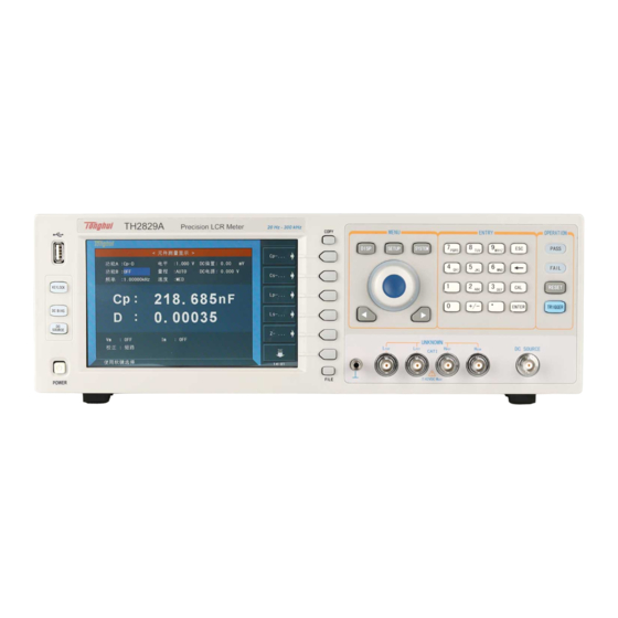
TH2829 Series
Tonghui TH2829 Series Manuals
Manuals and User Guides for Tonghui TH2829 Series. We have
1
Tonghui TH2829 Series manual available for free PDF download: Operation Manual
Tonghui TH2829 Series Operation Manual (223 pages)
Brand:
Tonghui
| Category:
Measuring Instruments
| Size: 2 MB
Table of Contents
Table of Contents
2
Chapter 1 Out of Box Audit
10
To Inspect the Package
10
Power Connection
10
Fuse
10
Environment
11
Use of Test Fixture
11
Warm-Up
11
Other Features
12
Chapter 2 Introduction
13
Introduction to Front Panel
13
Introduction to Rear Panel
15
Introduction to Display Zone
16
Main Menu Keys and Corresponding Displayed
17
Disp]
17
Setup]
17
System]
18
Basic Operation
18
Start the Instrument
19
Chapter 3 Introduction to [DISP]
20
Meas Display
20
Test Function
21
Test Range
23
Test Frequency
23
Test Level
24
DC Bias
25
Test Speed
26
Tools
26
Save LCR Test Result by U Disk
27
Bin No. Disp
28
Comparator Function
29
Bin Count Disp
29
Param
30
Nom
30
Bin
30
High/Low
31
Count
31
Aux
31
Out
31
List Sweep Disp
31
Sweep Mode
32
FREQ (Hz)
33
Cp[F] D[ ]
33
CMP (Compare)
33
Trace Sweep
33
Format
34
Scale
34
Read
34
Trace
35
Points
35
Trigger
35
Save Csv & Save as
35
Meas Setup
36
Trigger Mode
38
Auto Level Control Function
38
Bias Current Isolation Function
39
Average
40
Level Monitor Function
40
Delay Time
41
Output Impedance
41
Deviation Test Function
41
Correction
42
Open
44
Short
45
Load
47
Load Correction Test Function
48
Cable Length Selection
48
Limit Table
49
Swap Parameter
49
Limit Modes of Compare Function
50
Set Nominal Value of Tolerance Mode
51
Comparator Function ON/OFF
51
Auxiliary bin ON/OFF
52
High/Low
52
List Sweep Setup
53
Mode
54
Test Parameter
54
Sweep Parameter Setup
55
Trace Sweep Setup
55
Function
56
Level
56
DC Bias
56
Trace
57
Range
57
Scale
57
Frequency
57
Speed
57
Format
57
Trigger
57
Mode
57
Start Delay
58
Point
58
Step Delay
58
Maximum and Minimum
58
Start
58
End
58
Coordination Range Settiing
58
Chapter 4 [SYSTEM] and <FILE MANAGE
60
System Setup
60
Main Func
60
On Beepers
61
Pass Beep
61
Fail Beep
61
Language
62
Theme
62
Pass Word
62
BUS MODE (Reserved Function)
63
GPIB ADDR (Reserved Function)
63
Talk Only
64
Bias Src
64
Baud Rate
65
Data/Time
65
Lcr <File Manage
65
Setup File for Single-Group Component (*.STA)
66
U-Disk Manage Performance
67
Operation Steps for File Management
68
Chapter 5 Execute LCR Operation and some Examples
70
Correction Operation
70
Sweep Correction
70
Point-Frequency Correction
70
Correct Connection of DUT
71
Eliminate the Influence of Stray Impedance
72
Operation Example for Testing Inductance with TH2829AX
73
Operation Example of Testing Capacitance by Multi-Frequency List
75
Sweep
75
Operation Example of Load Correction
78
Chapter 6 Transformer Single-Machine Test
80
Circuit for Transformer Single-Machine Test
80
Some Parameters of Transformer
80
Transformer Single Test Circuit and TURN Test
80
Transformer Leakage Inductance Test
81
Capacitance Test between Windings of Transformer
81
Transformer Measure Setup
82
Delay
83
Bias
83
Mode
83
Setting TURN Test Conditions
84
Setting Lx Test Conditions
84
Setting DCR Test Conditions
85
Test Frequency, Voltage and Switch
85
Trans Limit Setup
85
Lmt Mode
86
Parameter Column
86
Trans Meas Disp
87
Transformer Judge Display
87
Save Transformer Single-Group Test Result by U Disk
88
Chapter 7 Transformer Auto Scanning Test
90
Introduction to Scan Test Function
90
Install and Connect the Scanning Test System
90
Upper Panel of Scanning Box
91
Lower Panel of Scanning Box
93
HANDLER Interface
93
Timing Diagram of HANDLER Signal
93
Example of Transformer
94
Distribution and Connection Diagram for HANDLER
94
Transformer ID
95
Clear Ram
95
Transformer Pin Label
96
Autotrig Delay
96
Handler Mode
97
Save Log Mode
98
COPY PINOFFSET and COPY A=>ALL
99
Pass Disp Time
100
Pass Disp Size
101
Command Extrig
101
Minus Dev
102
Scan Disp Font
102
Ext Reset Func
102
SCAN PAGE from and SCAN
102
Rescan if Fail
103
Save Log as
104
DC Bias Factor
104
Hdl Val ID Time
105
Relay Act Time
105
Transformer ID
106
Primary Nums
106
Secondary Nums
106
Rescan Interval
106
Scan Disp Mode
107
Fail Rescan
107
Dcr Meas Delay
107
Dcr over Delay
107
Ibias on Delay
108
Ignore Nom
108
Trigger Delay
108
Cylinder Ctrl
108
Allocate Pin to Fixture
109
Pin to Fixture
109
Hflx
109
Pin Setup
110
Series Pin Short Setup
111
Parallel Pin Short Setup
112
Trans Test Condition
113
Frequency, Voltage, Switch and Scanning Sequence
113
Setting TURN Test Conditions
114
Setting Lx Test Conditions
117
Setting Lk Test Conditions
121
Setting CX Test Conditions
122
Setting Zx Test Conditions
123
Setting ACR Test Conditions
125
Setting DCR Test Conditions
126
Setting PS Test Conditions
127
Setting BL Test Conditions
128
Setting LED Test Conditions
129
Trans Scan Test
131
Display Zone
131
Function Keys
132
PRI Page-Turning Function
133
Lk Pin Disp
134
BAL Display
135
File Manage
135
Operation Steps for File Manage
136
Stored Files of TH2829AX-24
138
Compatibility of Stored Files
139
Transformer Deviation-Deduction
139
Save Scan Test Results by U Disk
141
Statistic Page of Transformer Scan Test
142
Reset Statistic Count Value
142
Focus Scan
143
Frequently Asked Questions and Answers in Transformer Scan Test
144
High and Low Limits
144
Measurement Item Loss
144
Measurement Interruption
145
Poor DCR Accuracy
145
Poor Lk Accuracy
145
Inaccurate TURN
145
Unstable TURN
146
Difference between the First and the Second Lx
146
Poor Stability of CX and Zx Open Test Data
146
DCR and PS Open Cannot Reach Infinite Large
146
User-Made Test Fixture
146
Use TH1801-EXT2A-OUT to Make Test Fixture
147
Example of Using TH1801-EXT11A(5.0)-B Pin Signal
148
Scan Test Interface Board
148
Self-Check Function of Scanner Relay
149
Operation Steps for Scan Self-Check
149
Displayed Information on Screen
150
Detection Method for Relay Short
151
Chapter 8 Performance and Test
152
Test Function
152
Parameter and Symbol
152
Test Combination
152
Mathematical Operation
152
Equivalent Mode
152
Range
152
Trigger
152
Delay Time
153
Connection Modes of Test Terminals
153
Test Speed (Frequency>=10Khz)
153
Average
153
Display Digit
153
Test Signal
153
Test Signal Frequency
153
Signal Mode
154
Test Signal Level
154
Output Impedance
154
Monitor for Test Signal Level
154
Maximum Measurement Display Range
154
DC Bias Voltage Source
155
Diode Test
155
Measurement Accuracy
155
Z│,│Y│, L, C, R, X, G, B Accuracies
155
D Accuracy
156
Q Accuracy
156
Θ Accuracy
156
G Accuracy
156
Rp Accuracy
157
Rs Accuracy
157
Accuracy Factor
157
DCR Accuracy
161
Lk Accuracy
161
Turns to Ratio Accuracy
161
Safety Requirement
162
Insulation Resistance
162
Insulation Intensity
162
Leakage Current
162
Electromagnetic Compatibility
162
Performance Test
162
Working Condition
162
The Used Instruments and Devices
163
Function Check
163
Test Signal Level
163
Frequency
164
Measurement Accuracy
164
Accuracy of C and D
164
Accuracy of L
164
Accuracy of Z
164
Accuracy of DCR
165
Chapter 9 Command Reference
166
Subsystem Commands for TH2829X
166
Display Subsystem Commands
166
Frequency Subsystem Commands
169
Voltage Subsystem Commands
169
Current Subsystem Commands
170
Amplitude Subsystem Commands
170
Output Resistor Subsystem Commands
170
Output Subsystem Commands
171
BIAS Subsystem Commands
172
Function Subsystem Commands
173
LIST Subsystem Commands
177
Aperture Subsystem Commands
181
Trigger Subsystem Commands
182
Fetch? Subsystem Commands
183
Correction Subsystem Commands
186
Comparator Subsystem Commands
191
Mass Memory Subsystem Commands
196
TRAN Subsystem Commands
196
GPIB Common Commands
205
Chapter 10 Description for Handler
209
Technology Description
209
Operation Description
209
Advertisement
Advertisement
Related Products
Tonghui TH2822
Tonghui TH2822C
Tonghui TH2822A
Tonghui TH2821B
Tonghui TH2821A
Tonghui TH2827 Series
Tonghui TH2827C
Tonghui TH2827A
Tonghui TH2822D
Tonghui TH2822E
Tonghui Categories
Measuring Instruments
Test Equipment
Multimeter
Power Supply
Scanner
More Tonghui Manuals
Login
Sign In
OR
Sign in with Facebook
Sign in with Google
Upload manual
Upload from disk
Upload from URL