NON-PROFESSIONALS SHUOLD NOT OPEN THE REAR COVER Maintaining, substituting parts or adjusting instrument should made professional maintenance personnel. Please contact relevant distributor or Tonghui’s after-sale service department. DO NOT REMOVE OR MODIFY THE INSTRUMENT...
Page 4
Some replacements unauthorized modifications might cause irreversible damage to the instrument. SAFETY WARNING Strictly follow the relevant safety statements in this manual involving safety, personnel injury, damage to the instrument, operation and environmental conditions causing poor test.
Safety Guidelines To ensure that you use this device safely, follow the safety guidelines listed below: This meter is for indoor use, altitude up to 2,000 m. For short-time outdoor use, precautions should be taken to avoid direct sunlight, water moisture, electromagnetic...
Page 6
12VDC/150mA. If a power adapter is selected, please be sure to meet the safety requirements of a relevant IEC standard. battery using TH2822D/E rechargeable. charge non- rechargeable batteries. Safety Symbols This symbol is a warning and...
Page 7
Environmental Conditions 0 °C to 40 °C Operating Environment Storage Humidity 0 – 80% R.H. Storage Environment -20 °C to +50 °C Pollution degree...
Contents Safety Summary ............1 Safety Guidelines ............3 Introduction ............... 9 Package List ............10 
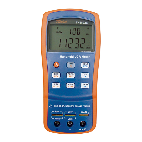
Front Panel Overview ..........12 Front Panel Display Descriptions ........13 Front Panel Buttons ............15 Button Function Definition ..........16 ...
Page 9
Operation Instruction..........32 Data hold mode (HOLD) ..........32 Data Record Mode (REC) ..........33 PRI Select Mode ............36 SEC Select Mode ............37 Test Frequency(FREQ) ..........37 Test Electric Level ............38 ...
Page 10
Direct Current Resistance Measurement ...... 78 Remote Communication ......... 78 Connecting Instrument to PC ........79 Virtual Serial Port Configuration ........81 RMT Operation ............. 82 Command Protocols ............. 84 Specifications ............99 General Specifications ..........
TH2822D/E provides the primary parameter of up to 40,000 readings, secondary parameter of 0.0001 reading resolution, maximum measuring frequency up to 100kHz, constant internal resistance of 100Ω...
TH2822D/E is equipped with the function of remote communication. The test data can be transferred to PC through a Mini USB connection, great for applications that require remote control and data acquisition.
Page 13
* This can be purchased as optional accessories. All contents are subject to actual package list or box. Please locate them from the original packaging to ensure nothing is missing. If in the case that an item is missing, please contact Tonghui or relevant distributor immediately.
Front Panel Display Descriptions 1. LCD display 2. USB communication / *Back light button 3. Power ON/OFF button 4. Frequency and record mode selection 5. Secondary display mode (D/Q//ESR, etc.)/ Test Level 6. Primary display mode (L/C/R/Z/DCR, etc.)/ auto LCR selection 7.
Page 16
NOTE: automatically cut off since the normal supply of external power. If the battery is rechargeable (TH2822D/E), the external power will charge the battery simultaneously. TH2822D/E is installed an independent charging controller--- — charging control is still done even at the state of power-off.
Front Panel Buttons With the exception of the power button, all front panel buttons have specific colored labels on them. They are all marked in black, blue or orange color. Each color has a specific representation, as described below: Black—the primary function, meaning...
LCD Display Overview L CR AUTO θQ MAXAVGMIN FASTSLOW Ω 2105% 0.1V0.3V0.6V μH μ Ω Figure 3 - LCD Indicator Display LCD Display Description 1. LDCRZ – Primary parameters display 2. MAX – Maximum reading indicator in the record mode...
Page 20
3. AVG – Average reading indicator in the record mode 4. MIN – Minimum reading indicator in the record mode 5. AUTO – Automatic LCR indicator 6. – Phase angle indicator for secondary display 7. D – Dissipation indicator 8.
Page 21
22. ESR – Series mode indicator for secondary parameters 23. DH – Data hold indicator 24. SLOW – measuring rate indicator 25. 2105% - Limits indicator in tolerance mode 26. FAST- Fast measuring rate indicator – Low battery/charging indicator 28. @OFF –Auto power-off indicator 29.
Special Display Indicators Indicates short clear if you press the CLEAR button Indicates open clear if you press the CLEAR button Error indication Indicates correction (open/short clear) mode Indicates damaged or open fuse (UNK)AD converter error(UNK) AD converter error(END)...
Test Port TH2822 series are creatively designed to combine 3- terminal port and 5-terminal port, which makes the convenient test and highly accurate test realized in the instrument. 5-terminal 1-High test slot Potential 2-Low Potential 3-terminal 3-Protect test port Potential Figure 4- test port With the adoption of standard banana slots, the instrument...
quite convenient. However this configuration has low testing accuracy. For the improvement of accuracy when using external testing leads, TH2822 series are designed with 5- terminal testing slots and exclusive test fixture to ensure complete external 4-terminal test measuring accuracy. NOTE: TH26027A, TH26009C and TH26029C 4- terminal test fixtures are optional for TH2822 series.
Installing Battery TH2822D/E can adopt battery for power supply so that you can take measurements whenever and wherever without much preparation. 8.4V alkaline batteries used in TH2822D/E are rechargeable. Reference standard is LH-200H7C. Do not use non-rechargeable batteries with the exception of emergency cases.
Page 26
(See Figure 6). Be sure to insert the battery with matching polarity. 3. Place the battery compartment cover piece by sliding it into the top slid first. Place screw at the bottom of the cover piece and tighten down with a screw driver. 4....
Figure 6- Battery Compartment Connecting External Power Source TH2822D/E is equipped with standard external power adapters, which can use external source.
Page 28
WARNING: Use the included or specified adapter only. Confirm power parameters be ones that adapters require before use. To connect the adapter, do the following: 1. If a battery is installed, please check the battery compartment again that the polarity of the battery matches the polarity as indicated by the labels inside the compartment.
12VDC input AC adapter Figure 7-Connecting AC Adapter to Meter NOTE: The meter will automatically switch to consume power from the AC adapter instead of the battery when an AC adapter is plugged in and consume the power normally. In this event, if the battery installed correctly is rechargeable, charging controller will be driven at the same time no matter the instrument is on or off.
battery voltage is below normal working voltage (below 6.8V). It is highly recommended that the battery be replaced as soon as possible before continuing operation. See “Installing Battery” for instructions. If the battery is rechargeable, when the indicator starts flashing, please charge the battery before continuing operation.
Page 31
When Using Battery Power When the meter is powered by using battery, the brightness of the back light will automatically decrease to conserve battery power. When the back light have lightened for about 15 seconds, the brightness will continuously decrease; and when the back light have lightened for approximate 30 seconds, the back light will automatically turn off.
Charge Display The power circuit of TH2822D/E is rechargeable. When the external power adapter is plugged in, the power mode will automatically switched and charge the internal chargeable battery. Single charge circle is about 160 minutes and charge current is approximate 120mA. If a battery is full charged, the charge will be automatically shut off;...
Page 33
indicator will be light up in the condition of being charged no matter the instrument is off or on.
Operation Instruction Data hold mode (HOLD) The data hold function allows the user to freeze the display data. The data displayed on LCD will not be updated upon the phase of test. Turn On Data Hold To use data hold, press the HOLD button. The “DH” indicator will display on the screen when data hold is active.
Turn Off Data Hold To disable the data hold, press the HOLD button again. The “DH” indicator will disappear on the screen, and meter will remain in normal operation mode. Data Record Mode (REC) If the data stability of tested components is poor and the data fluctuates in a range, data record mode can aid the reading of data.
Page 36
Using Static Recording There are four different modes that can be selected in static recording. Per press of the REC button (in recording mode, FREQ will disable), the modes will change and repeat in the following order: Recording mode Maximum Mode Minimum Mode Average Mode...
Page 37
Maximum Display Press REC button until the “ MAX ” indicator is shown on display. This indicates that the value in the primary display represents the recorded maximum value. Minimum Display Press REC button until the “ MIN ” indicator is shown on display.
Disable Static Recording To exit this mode, press and hold the REC button for a long time. The “MAX”, “MIN”, or “AVG” indicator will disappear on LCD. NOTE: Changing the type of test parameters will automatically turn off static recording. PRI Select Mode To select measurement mode, you should select primary parameter first.
Q (Quality factor), θ (Phase angle), and ESR (Equivalent series resistance). Test Frequency(FREQ) TH2822D/E handheld LCR meters apply AC signal to DUT for measurement. Frequency is among the main parameters of AC signal. By the presence of component’s non-ideality and distributed parameters,...
FREQ button, the meter will change among the following selectable frequencies: TH2822D : 100Hz/120Hz/1kHz/10kHz TH2822E : 100Hz/120Hz/1kHz/10kHz/100kHz Test Electric Level TH2822D/E handheld LCR Meter uses AC signal applied to the item measured (DUT) test. The level is the amplitude of the AC signal, due to the...
Tolerance Mode (TOL) tolerance mode specifically used component sorting purposes. In tolerance mode, secondary display indicates the range of percentage. Tolerance mode, nominal value and sorting limit just come into play on primary parameters. The selectable range for sorting is as follows: 1%,5%,10%,20%. In tolerance mode, the data indicated in the primary display will be recorded as nominal value.
Page 42
Use Tolerance Mode To use the tolerance mode as the process shown below: 1. Select the desired primary measurement mode by pressing PRI button. 2. Configure the proper test frequency and series/parallel equivalent mode. 3. Perform the operation of CLEAR appropriately if necessary.
Page 43
including data hold, MAX, MIN, AVG data recording, etc. 6. If sorting is not necessary, you can skip this step. If it is necessary, by pressing the TOL button you can select the range of 1%,5%, 10% or 20%, which will be shown on LCD accordingly.
Auto LCR Mode Auto LCR function will automatically select the corresponding primary and secondary parameters and suitable series/parallel equivalent mode of L, C, R. The selection is done by judging the impedance property of component according to the test result. It is quite convenient for the measurements of mixed and unknown components.
Page 45
Table1-Matching relations between primary and secondary parameters in auto LCR mode Secondary Primary Parameter Parameter Capacitance (C) Dissipation (D) Inductance (L) Quality Factor (Q) Resistance (R) Phase Angle (θ) In auto LCR mode, series or parallel equivalent mode is selected in accordance with the magnitude of impedance.
“AUTO” indicator on LCD will disappear when auto LCR mode is turned off. Measurement Rate (RATE) There are two selectable measurement rates in this instrument: fast slow. rate fast measurement is about 4~5times/sec and slow measurement is approximate 1.5 times/sec. The stability of slow measurement is higher than fast measurement.
Page 47
frequently taken as combined network of ideal components. In general, there are two simple equivalent models used in LCR meters, which are series model and parallel model. Figure 8-Series and Parallel Equivalent Models of Inductors and Capacitors Appropriate equivalent modes could help to gain better measurement results.
Selecting Measurement Mode Long press P<->S button, “PAL” on LCD indicates parallel equivalent mode and “SER” means series equivalent mode. Default Equivalent Mode In this mode, default equivalent mode varies with primary parameter: For capacitors and resistors, default equivalent mode is PAL; for inductors, SER. Utility Menu (UTIL) The LCR meter has a built-in utility menu that allows you to configure some user preferences and settings.
Page 49
colored in blue. There are three buttons: UTIL, , . User can configure the beep tone, auto power-off timing, store/restore power-on state, view the battery voltage, etc. Entering Utility Menu Long press UTIL button will enter utility menu. Primary display is menu option and secondary display is the current settings or parameters configured for the selected option.
Page 50
Table 2-Utility Menu Options and Settings Menu Options Settings/Parameters dCdly DCR trigger delay ON / OFF ‘bEEP AoFF 5 / 15 / 30 / 60 / OFF PrE / Set yES / NO bAtt Battery Voltage Uses of these menu options are as follows: DCR trigger delay function: (dCdLy: DCR delay) Control beep sound: (...
Page 51
each menu options and will repeat itself in the following order: dCdLy bEEP AoFF PuP dEF bAtt change settings different NOTE: application effects in accordance with different exiting mode. See “ Exit Utility Menu ” section (Saving and Exiting, Exiting without Saving) for details.
Page 52
Beep Sound Setup (bEEP) The “bEEP” menu option allows the user to enable or disable the beep sound for every key press. NOTE: This option only disables the beep sound for each key press. It does not disable the beep sound for “Tolerance”...
Page 53
display shows “AoFF”, push the and arrow keys to select the timer setting. The settings will be shown on the secondary display as Table 3. When AoFF is effective, this timer is always counting continuously; when the configured time is up, the meter will make an audible “...
Page 54
60 minutes Manual power off only The setting will be immediately effective. But this state will not saved if choose “Exiting without saving”; “Saving and exiting” should be implemented if this setting needs to be effective after restarting. Default Setting: 5 Power-up State (PuP) The “PuP”...
Page 55
Reference value for Tolerance mode Measurement rate In the utility menu, Press the and arrow keys to select“PrE”or“SEt”. PrE means to preserve the previous setting while SEt means to save the current parameter, that is, cover the original data. NOTE: Exiting mode decides whether to implement SEt.
Page 56
utility menu, exit first and enter into utility menu after measuring setup. 2. Press UTIL button for a long time to enter into utility menu. 3. Push the UTIL button to traverse through the utility menu until you see “ PuP ” on the primary display.
Page 57
Prevent Overwrite of Stored Settings In the utility menu, the “PuP” option default setting is always “ PrE ” . If it is required to overwrite previously stored settings for power-up state, the option should change to “SEt”. Therefore, when entering the utility menu, be sure not to change to “SEt”...
Page 59
Settings Default Configuration Primary Function C (capacitance) Secondary Function None (frequency) Auto LCR function Equivalent Method SER (series) Measurement Frequency 1kHz Measurement Level 0.6V Measurement Speed Slow (SLOW) Tolerance Mode Beep Sound Auto Power-off Timing 5 minutes Stored Measurement clear Setup Stored Utility Menu clear...
Page 60
In “dEF” option, push either or button to choose “ NO ” or “ yES ” . “ NO ” means the instrument will not be set back to default. “yES” indicates to reset all settings to default and to clear previously stored setup.
Page 61
Indicate battery voltage(bAtt) When menu option changes to “ bAtt ” , the secondary display will indicate battery voltage that is for reference instead of for operational function. Exit Utility Menu There are two methods for exiting the utility menu: Saving and Exiting, Exiting without Saving.
Page 62
“Saving” refers to preserve corresponding information in the built-in non-volatile memory. Therefore, data will not lose at the time of power-off and can be used at the time of power-on. Exiting Without Saving If user decides to exit the utility menu without making any changes or saving any changes to “PuP”...
Clear Functions (CLEAR) There are two functions under CLEAR: Open Clear and Short Clear. Clear can decrease the distributed error caused by test leads, for instance, short clear can reduce the effects of contact resistors and test leads and open clear will minimize the influence of distributed capacitors and resistors on testing high impedance elements.
Page 64
Open Clear First select frequency to clear and keep test clip and test slot be open. Enter into clear by the press of CLEAR, and a moment later the OPEN indicator will appear on secondary display after the automatic measurement judging. If user decides to perform open clear, another press of CLEAR should be done.
Page 65
Short Clear First choose test frequency to clear and then insert a short plate to test slot. If SMD test tweezers or test clip is used, the short plate should cut off the test terminal. Enter into clear by the press of CLEAR, and a moment later the SHrT indicator will appear on secondary display after the automatic measurement judging.
Page 66
Figure10-Short Clear Quick Clear Procedure Below is an example of steps to follow to do open or short clear: 1. Select the primary and secondary function mode for measurement; 2. Select test frequency; 3. Select equivalent mode; 4. Keep the test terminal open to perform open clear;...
Page 67
NOTE: 1. Clear data is just temporarily stored in RAM, which means that the data will loss after power-off. Therefore “ clear ” , prior to measurement, should be first done after power-on. 2. Clear data is stored under different frequency, thus they will be still valid at the change of test frequency (for instance, under the frequency of 1kHz, the meter has been cleared;...
Remote Control(RMT) When button used remote communication, please “REMOTE COMMUNICATION” section for details. Fuse Detection The meter has an internal fuse in the test signal terminal that protects the inputs from severely damaging the instrument. When the fuse is burned out, the “FUSE”...
Page 69
Figure 11-Fuse Display In the event that the above screen is displayed, the instrument should be powered off. If this does not power off the meter, remove external AC adapter if that is used and/or remove the battery from the battery compartment.
Quick Start Guide CAUTION Do not measure a capacitor that is not fully discharged. Connecting a charged or partially charged capacitor to the input terminals will damage the instrument. When measuring an on- board component within a circuit, the circuit must be powered off before connecting the test leads.
Before removing the cover, ensure that none DUT is connected to the meter and the instrument is disconnected from any circuit and is powered OFF. NOTE: To achieve optimum precision, please see “ Clear Function ” for details before testing. Inductance Measurement 1.
Page 72
4. Press the FREQ button until the desired test frequency is displayed on screen. 5. Press the LEV button until the desired test level is displayed on screen. 6. Press the SEC button to select the desired secondary parameter. 7. Read the readings on LCD for inductance measured values.
Page 73
Below are TH26027A, TH26009C and TH26029C 4- terminal test accessories: TH26029C SMD KELVIN TWEEZER GUARD TH26009C SMD KELVIN TWEEZER GUARD TH26027A KELVIN CLIP GUARD Figure 13- 4-terminal Test Accessories...
Capacitance Measurement WARNING: Before testing, ensure that the tested capacitor has been fully discharged. 1. Press the POWER button for a long time to turn on the meter. 2. Press the PRI button until “C” is displayed on the screen to select capacitance measurement. 3.
Page 75
components may take longer to discharge. In these cases, please allot enough time for a full discharge. proper discharging component is not done correctly, it will damage the input terminals of the meter. 5. Press the FREQ button until the desired test frequency is displayed on screen.
TH2822E AUTO 100Hz - 100kHz Handheld LCR Meter HOLD UTIL FREQ RATE CLEAR AUTO Figure 14- Capacitance Measurement Resistance Measurement 1. Press the POWER button for a long time to turn on the instrument. 2. Press the RPI button until “R” is displayed on the screen to select inductance measurement.
Page 77
3. Insert a resistor into test slots or connect a tested resistor through a proper test accessory (e.g., banana plug-crocodile clip test leads, test fixture or SMD test tweezers). See figures 15 below. Figure 13 shows the optional 4-terminal test accessories.
Page 78
T H 2 8 2 2 E A U T O k H z P A L O F F Ω 1 0 0 H z - 1 0 0 k H z H a n d h e ld L C R M e te r R M T H O L D U T IL...
Impedance Measurement 1. Press the POWER button for a long time to turn on the instrument. 2. Press the PRI button until “Z” is displayed on the screen to select impedance measurement. 3. Insert impedance (resistor, capacitor or inductor) into test slots or connect tested impedance through a proper test accessory (i.e., banana plug-crocodile clip test leads, test fixture or SMD test tweezers).
Direct Current Resistance Measurement Press the POWER button for a long time to turn on the instrument. Press the PRI button until “DCR” is displayed on the screen to select direct current resistance measurement. Insert impedance (resistor, capacitor or inductor) into test slots or connect tested impedance through a proper test accessory (i.e., banana plug-crocodile clip test leads, test fixture or SMD...
Follow the below procedures for connection setup. 1. Install USB driver from CD or download the USB drivers from www.tonghui.com.cn. 2. With a Mini-USB cable, connect one end of it to the LCR meter and the other end to an available USB port on PC.
Page 82
6. Open the control software and use the assigned serial number to communicate with the handheld LCR meter. Download the FastAccess PC communication software from our web site (www.tonghui.com.cn). TH2822E L CR AUTO MAXAVGMIN θQ FASTSLOW Ω 2105% 0.1V0.3V0.6V μH μ...
Virtual Serial Port Configuration Below is the serial communication configuration of TH2822D/E: Baudrate:9600 Data bits: 8 Parity: None Stop bits: 1 Flow Control: None Upon the installation of USB driver, if the default assigned by serial port does not conform to above...
RMT Operation In the case of communication, the RMT button is used to change the running modes: Change to Local Operation in Remote Control Mode; Change to Auto Fetch function in Local Operation mode. NOTE: Auto Fetch means to send testing result automatically without needing the initiative inquiry of Remote Mode Upon the acceptance of any commands from PC, the...
Page 85
That is to say, among panel operation, Auto Fetch and Remote Control, remote control has the highest priority. To exit remote control, press the RMT button. When the “RMT” indicator disappears on the LCD display, the meter goes back to local operation. NOTE: If the local operation is locked, RMT button will be ineffective as well.
Fetch will be disabled. To re-enable Auto Fetch after remote command, first press the RMT button to return panel operation and then enter into Auto Fetch mode by another press of RMT. Command Protocols Overview TH2822D/E employs SCPI commands with ASCII character strings transmitting control commands and...
Page 87
returning query information and data and with a specified terminator identifying the termination of a command line or query data line. The adoption of SCPI commands brings convenience for the interaction control of PC on the meter through programming. Command format is compliance with specifications and easy for understanding and use.
Page 88
Termination Character A terminator is a character sent by a host, which identifies the end of a command string. Only when a termination character is received, the instrument will analyze and deal with command character string. Terminators can be any one of the following character strings: <CR>...
Page 89
<Primary measured data, Secondary measured data, Tolerance Result> <CR> <LF> Data Types Table 5 below explains the different data types transmitted on bus with ASCII characters: Table 5 - Data Type Data Type Explanation Example <NR1> Integer +800,-200,100,-50 <NR2> Integer +1.56,-0.001,10.5 This representation has an explicit radix...
Page 90
Symbol Convention Syntax Symbols in Commands Below symbols is a part of commands: Syntax Explanation Symbol Colon means to enter into next command level same command level common command multi-parameter delimiter inquiry ? Space, separate commands from parameters “ ” quoting part Command Specifier Below symbols are used for the description of...
Page 91
Table 6-Command Specifier Mark Symbol Explanation Option; can be omitted Exclusive OR < > Defined element Comment Abbreviation, upper case and lower case commands 1. There are two command formats: complete format and abbreviated format. In the following command description, upper case commands are abbreviated commands.
Page 92
3. It is not important to distinguish the real transmitted ASCII commands or parameter letters on bus. Command Reference Common Command *IDN? Query instrument ID. Return: <instrument model>, <firmware version>, <serial number> *LLO Local Lockout. This means that all front panel buttons, including the RMT key is not available.
Page 93
*GTL Go to local and remove local lockout. If *LLO is sent, the only way to operate front panel is to go to *GTL. *TRG Trigger the instrument to take a measurement. Due to the automatically continuous test, *TRG command is of no use.
Page 94
FREQuency? Description: Query the current test frequency Return: <100Hz|120Hz|1kHz|10kHz|100kHz> VOLTage subsystem VOLTage <value> Description:set the test level (only effective in L,C,R,Z) Parameters are 0.3, 0.6, 1 or 3e-1,6e-1,1e0 Example: VOLTage 0.3 Set the test level to 0.3 V VOLTage? Description: set the current test level Return:<0.3V|0.6V|1V>...
Page 95
FUNCtion:impb < D | Q | THETA | ESR > Description: Select the secondary parameter (only effective in L,C,R,Z) Example: FUNCtion:impb D Select D as the secondary parameter FUNCtion:impb? Description: Query the secondary parameter (only effective in L,C,R,Z) Return: <D, Q, THETA, ESR, NULL> FUNCtion:EQUivalent <...
Page 96
CALCulate subsystem CALCulate:TOLerance:STATe < ON | OFF > Description: Enable or disable tolerance mode Example: CALCulate: TOLerance:STATe ON CALCulate:TOLerance:STATe? Description: Query the tolerance mode Return: <ON, OFF > CALCulate:TOLerance:NOMinal? Description: Query the nominal value Return: NR3 or -----(exceeding data range) CALCulate:TOLerance:VALUe? Description: Query the percentage value of tolerance...
Page 97
CALCulate:RECording:STATe < ON | OFF > Description: Enable or disable recording function Example: CALCulate:RECording:STATe ON CALCulate:RECording:STATe? Description: Query the recording state Return: <ON or OFF> CALCulate:RECording:MAXimum? Description: Query the maximum value of recording function Return: <NR3, NR3> ( primary and secondary parameters, when data exceeds limits or there is no data, what returns is“----”.) CALCulate:RECording:MINimum?
Page 98
Description: Query the present value of recording function Return: <NR3, NR3> ( primary and secondary parameters, when data exceeds limits or there is no data, what returns is“----”.) FETCh Subsystem FETCh? Description: Returns the primary, secondary display value and tolerance compared result (BIN no.).
Page 99
Summary of Supported SCPI Commands Table 7 - Summary of SCPI Commands Command Parameter Explanation FREQuency <Value> Set the Test Frequency FREQuency? Query the Test Frequency VOLTage <Value> Set the Test level VOLTage? Query the Test level FUNCtion :impa <Literal> Select the primary display parameter :impa?
Page 100
tolerance :RANG <Value> Set the limit bin :RANGe? Query the limit bin :RECording :STATe <Boolean> Enable/disable the recording function :STATe? Query the recording state :MAXimum? Query the max. value of recording :MINimum? Query the min. value of recording :AVERage? Query the average value of recording :PRESent? Query the test value of...
E11: Parameter Error E12: Syntax Error Specifications Below are the general specification and the accuracy specification of TH2822D and TH2822E. Declaration: The specifications are subject to change without notice. *NOTE: 120Hz is the fixed frequency. The actual frequency is 120.048Hz.
General Specifications Function Measurement Parameters Primary: L/C/R/Z/DCR Secondary: D/Q/θ/ESR Equivalent Mode Series, Parallel Auto LCR Function Manual, Auto Ranging Mode Auto Test Terminals 3-terminal,5-terminal Measurement LCRZ 4 meas/sec,1.5meas/sec Speed 3 meas/sec,2.5meas/sec Short, open Correction 1%,5%,10%,20% Tolerance Mode Input Protection Fuse 0.1A / 63V Interface Mini-USB (virtual serial...
Page 103
TH2822 100Hz,*120Hz,1kHz,10k Hz,100kHz Test Signal Level(10% accuracy) 0.3 Vrms、0.6Vrms、1 Vrms DCR signal:1Vdc Output Impedance 100Ω Display Display LCD primary-secondary dual display Backlight Battery supply: when backlight is on, luminance is reduced by half 15s later and automatically turned off 30s later. Powered by adapter: backlight off until manually turned off Count...
Page 104
0.0000 -- 9999 0.0001 θ -179.9° -- 179.9° 0.01° Power Supply Battery Model LH-200H7C,8.4V Ni-MH 200mAH rechargeable battery AC Adapter Input 220V(1±10%) 50Hz(1 : , ±5%) Output 12V-15V DC : Operating Current (with Max.:35mA backlight off) Typical:25mA (@1kHz, 0.6 Vrms,100Ω load) Standby Power Off Current (...
Page 105
General Operation Temperature 0℃ -- 40℃ Condition Relative Humidity ≤90% R.H. Weight 350g Dimensions (H ´ W ´ D) 190mm *90mm *41mm Safety and EMC compliance IEC 61010-1:2001 IEC 61326-2- 1:2005...
Accuracy Specifications Notices 1. Environment temperature : 23 ℃ ± 5 ℃ ; Humidity: ≤75% R.H. 2. Valid after 10 minutes of warm up time. 3. Test in measuring slots on front panel. 4. Measurements performed after correct open and short correction. 5....
Page 107
S—series equivalent; p—parallel equivalent; e: accuracy 10. Some parameters cannot expressed as the way of data sheet; therefore they can just be converted by formulas according to corresponding results. Inductance (L) and Quality Factor (Q) Recommended Accuracy Accuracy Range Display Range Equivalent De * Mode...
Page 116
: actual impedance, φe is the phase angle accuracy, Notice: The accuracies of ESR and Rs are same. Equivalent Parallel Resistance Accuracy of equivalent series resistance is calculated according to the below formula: ...
Maintenance WARNING: Do not perform any service by yourself. Service should only done by qualified personnel and trained technicians. WARNING: Beware of liquid residues, especially conductive matter. Service If the instrument fails to power on, first check battery, external source and power sockets and the validity of buttons.
The meter must be turned off or removed from external power before replacing battery. See Installing Battery section for details. Cleaning Before cleaning this meter, make sure the power is OFF and remove external AC adapter if one is used. To avoid electrical shock or damaging the meter, prevent water from getting inside the case.
Limited Warranty The instrument, component parts and accessories will be free from defects in workmanship and materials for a period of two years from date of purchase. Tonghui will, without charge, repair or replace, at its option, defective product component parts.
Need help?
Do you have a question about the TH2822D and is the answer not in the manual?
Questions and answers