Table of Contents
Advertisement
Quick Links
Advertisement
Table of Contents

Related Manuals for Tonghui TH2512


Summary of Contents for Tonghui TH2512
- Page 1 TH2512 DC Milliohmmeter Instruction Manual...
-
Page 2: Table Of Contents
Warranty ..............................3 Safety Precautions............................ 4 Chapter 1. Introduction ........................5 Unpacking and Inspection ....................... 5 Product Overview ........................5 Controls and Indicators......................6 1.3.1 Front Panel Controls and Indicators............... 6 1.3.2 Rear Panel Controls and Connectors ..............7 Installation ..........................7 1.4.1 Dimensions ........................ -
Page 3: Warranty
This Tonghui instrument product is warranted against defects in material and workmanship for a period of one year from the date of shipment. During the warranty period, Tonghui company will, at its option, either repair or replace products which prove to be defective. For warranty service or repair, this product must be returned to a service facility designated by Tonghui. -
Page 4: Safety Precautions
(especially capacitors) can store charge and may cause a hazard if not discharged properly. Follow these safety instructions. 1. Operate the TH2512 unit with its chassis connected to earth ground. The instrument is shipped with a three-prong power cord to provide this connection to ground. This power cord should only be plugged in to a receptacle that provides earth ground. -
Page 5: Chapter 1. Introduction
TH2512 instrument. The effects of series resistance in the test leads can be zeroed with the short correction function. The TH2512 instrument is equipped with Pass/Fail bins. High and low limits set in the Comparator function display the measured result as a percent. -
Page 6: Controls And Indicators
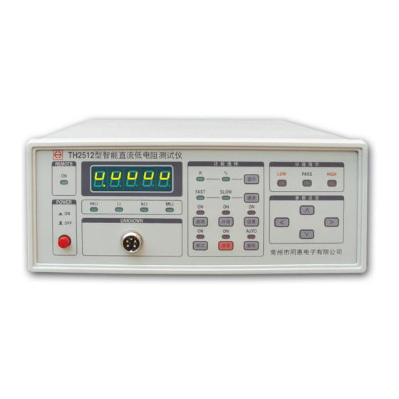
Controls and Indicators 1.3.1 Front Panel Controls and Indicators Figure 1-2 illustrates the controls and indicators on the front panel of the TH2512 DC Milliohmmeter instrument. Table 1-1 identifies them with description and function. TH2512 DC M illiohmmeter REMOTE FUNCTION... -
Page 7: Rear Panel Controls And Connectors
270 mm×110 mm×330 mm 1.4.2 Power Requirements The TH2512 can be operated from a power source of 190 to 250V AC. Power connection is via the rear panel through a standard receptacle. Always use an outlet that has a properly... -
Page 8: Safety Inspection
1.4.3 Safety Inspection Before operating the instrument inspect the fuse holder on the rear of the TH2512 instrument to ensure that the properly rated fuse is in place, otherwise damage to the unit is possible. Make sure the instrument is only used with the approved international cord set to ensure that the instrument is provided with connection to protective earth ground. -
Page 9: Zeroing
1.5.5 Zeroing Short circuit compensation 1.5.6 Comparator LOW, PASS and FAIL indication. Comparator parameters setup: Nominal, Hi and Lo Limits 1.5.7 Display 4 1/2 digits LED display. 1.5.8 Beep Alarm Beep alarm for PASS can be turned on/off by the switch from the rear panel. 1.5.9 Interfaces Standard Interfaces: Handler Optional Interfaces:... -
Page 10: Environmental
1.5.13 Environmental Specifications: 10℃ to 30℃, <75% RH Operating: 0℃ to 40℃, <75% RH Storage: -25℃ to 55℃, <90% RH 1.5.14 Power 198-242VAC 50Hz/60Hz Consumption <30VA... -
Page 11: Chapter 2. Operation
Power is applied to the TH2512 instrument by pressing the red power switch on the front panel to the ON position. The TH2512 unit should warm up for a period of at least 15 minutes prior to measurements being made. -
Page 12: Comparator Function
8. The first digit flashes. Use the ← key and → key to select which digit to be modified. 9. Use the ↑ key and ↓ key to increase or decrease the flashing bit. 10. Press SETUP key again, the TH2512 will return back to the measurement state and the SETUP led turns off. -
Page 13: Zero
RANGE The TH2512 instrument’s measurement range can be set as AUTO or HOLD. TH2512’s measurement ranges are 20mΩ, 200mΩ, 2Ω, 20Ω, 200Ω, 2kΩ, 20kΩ, 200k Ω and 2MΩ.The instrument default setting is AUTO Range. Perform the following steps to set the range mode. -
Page 14: Beeper
Beeper The beeper alarms when the device under test is sorted into PASS Bin. The beeper can be turned off from the rear panel. -
Page 15: Chapter 3. Handler Interface
Turn on comparator function, the comparison results will be sent out through the Handler interface. And the TH2512 can be triggered through the handler interface. The pin assignments is shown as table 2-2 and the timing diagram is shown as figure 2-2.
Need help?
Do you have a question about the TH2512 and is the answer not in the manual?
Questions and answers