
Related Manuals for IMPPUMPS NMT Smart C


Summary of Contents for IMPPUMPS NMT Smart C
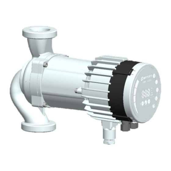
- Page 1 NMTC module Installation and operating manual for NMT Smart C NMT Max C NMT Lan C 7340055, v26, for software revision 2.239 onwards...
-
Page 2: Table Of Contents
WARNING! Prior to installation and commissioning, read these instructions first. Installation and operation must comply with local regulations. WARNING! Installation and use of this product requires experience and knowledge of this or similar products. Persons with reduced physical, mental or sensory capabilities must not use this product, unless properly instructed and supervised. -
Page 3: Symbols And Conventions Used In This Document
1. SYMBOLS AND CONVENTIONS USED IN THIS DOCUMENT WARNING! Denotes that a failure to observe those instructions might cause damage to equipment or pose danger to the user. NOTE: - Gives additional tips or instructions that might ease the job and ensure proper operation. NOTE: ... -
Page 4: Introduction
This manual describes the NMTC module for NMT range of pumps that is either integrated (NMT LAN C) or separately (NMT Smart C and NMT MAX C) available. Purpose of this module is to provide communication interface to the pump. - Page 5 RS-485 Connector type Screwless terminals 2+1 pins. See section 3.1 Terminals Data protocol Only one at a time. Modbus RTU Bus wire Two-wire + common Conductors: A, B and COM (Common). configuration See section 3.1 Terminals Communication Integrated, 1/8 of Connect either via passive taps or daisy chain.
- Page 6 Analog signals (SET1, SET2, SET3) Input voltage range -1..32 VDC When used as input. Output voltage 0..12 V When used as voltage output. 5 mA max. Load source range allowed per output. Input resistance ~100 kΩ 0.5 mA load is added for most configurations. Output current sink 0..33 mA (4-20 mA) Current sink to COM if configured as current...
-
Page 7: Module Layout
3. MODULE LAYOUT 3.1. TERMINALS Terminal Terminal description Designation MODE Mode selection rotary switch. Position read at power-on. Used to configure mode of operation for the circuit. See section 4.3 “Module mode selection”. LED1 / LINK Slowly blinking when module is powered. Blinking fast on Modbus Error Permanently lid when Ethernet link established. -
Page 8: Application Examples
3.2. APPLICATION EXAMPLES Relay, Analog and Modbus connection Relay and Ethernet connection NOTE: To maintain pump IP (ingress protection), the network cable should be pulled through the gland inlet and then crimped to a connector. -
Page 9: Wiring Considerations
3.3. WIRING CONSIDERATIONS All cables connected must be heat-resistant to at least +85 °C. All cables connected must be installed in accordance with EN 60204-1. All wires to the communications module must be connected to the terminals or cut. No loose wiring permitted. - Page 10 Disconnect display panel cable to ease access to the module wiring. Wiring can now be connected. Connect the NMTC module with power electronics. Make sure that the position tab and position slot are aligned.
- Page 11 Push the NMTC module back to the heat sink...
-
Page 12: Connecting The Module Wiring
3.5. CONNECTING THE MODULE WIRING Only for NMT Smart and NMT MAX pump models. Opening the cover WARNING! Before performing any work on the module, make sure that the pump and module electricity supply has been switched off and that it cannot be accidently switched on. - Page 13 Closing the cover WARNING! Before performing any work on the module, make sure that the pump and module electricity supply has been switched off and that it cannot be accidently switched Reconnect display panel cable. Make sure that the position tab and position slot are aligned.
-
Page 14: Control Modes And Priorities
4. CONTROL MODES AND PRIORITIES 4.1. PRIORITY OF SETTINGS Several signals will influence the pump operation. For this reason, settings have priorities as shown in the table below. If two or more functions are active at the same time, the one with highest priority will take precedence. Pump control panel &... -
Page 15: Module Mode Selection
4.3. MODULE MODE SELECTION WARNING! Before performing any work on the module, make sure that the pump and module electricity supply has been switched off and that it cannot be accidently switched on. There is a mode selection rotary switch in the terminal box. It can be rotated by gently inserting a screwdriver into the arrow mark on top and rotating the switch to desired value. -
Page 16: Mode 1 (2
4.4. MODE 1 (2..10V) Mode 1 is most often used mode of operation. It has 2 pre-prepared inputs that can be used for either digital control or with analog control voltages. Additional 10.5V output provides voltage feedback for analog or digital control. - Page 17 Contact position Function Description Stop the pump The pump is stopped The pump will run with internal set point Start the pump The pump will run with minimal speed for selected regulation mode Minimum curve The pump will run with maximum speed form selected regulation mode Maximum curve...
-
Page 18: Analog Control
ANALOG CONTROL Mode 1 connection configurations (analog) - Page 20 Function voltage voltage < 2 V < 1 V Pump stopped > 3 V < 1 V Internal regulation < 2 V 2..10 V Minimum curve > 3 V 2..10 V Figure 1: External 2..10 V transfer curve for Mode 1 0..10 V (RUN+MAX) Figure 2: External 0..10 V transfer curve for Mode 1...
-
Page 21: Mode 2 (0
4.5. MODE 2 (0..10V) Mode 2 is used for external 0..10 V voltage control. Terminal Signal function designation SET1 / RUN RUN input. Signal load 0.5 mA. COM / 0V Common ground for voltage input. SET2 / MAX SPEED input. Signal load 0.5 mA SET3 / FB 10.5 V feedback voltage for SET1 and SET2. -
Page 22: Mode 3, 4 (Pwm)
Function voltage voltage < 2 V 0..10 V Pump stopped. > 3 V 0..10 V Figure 3: External 0..10 V transfer curve for Mode 2 4.6. MODE 3, 4 (PWM) Mode 3 and 4 is used for PWM control and feedback according to IEC 60469-1. The difference between these two modes is in response to PWM-in signal. - Page 23 Mode 3, Mode 4 connection configurations ETHERNET LED2 LED1 RELAY MODE RS 485 To controller PWM-out PWM common PWM-in...
-
Page 24: Mode 3 (Solar)
MODE 3 (SOLAR) SET1 (PWM-in) function < 7 % Standby (pump stopped) 12..15 % Minimum setpoint 15..95 % Pump setpoint increases linearly with input > 95 % Maximum setpoint 0..100 % Figure 4: PWM solar transfer curve... -
Page 25: Mode 4 (Heating)
MODE 4 (HEATING) SET1 (PWM-in) MODE 4 (HEATING) function < 5 % Pump at maximum speed 5..85 % Pump setpoint decreases linearly with input 85..88 % Minimum setpoint > 93 % Standby (pump stopped) 0..100 % Figure 5: PWM heating transfer curve PWM OUTPUT SET2 (PWM-out) Status... -
Page 26: Relay Output
5. RELAY OUTPUT Terminal Terminal description designation MODE Mode selection rotary switch. Used to show and configure mode of operation for relay. LED1 / LINK Slowly blinking when module is powered, permanently lid when link established LED2 / ACT Flashing yellow when data reception detected. Combined (OR) with Modbus data reception indication Normally closed relay contact. -
Page 27: Rs-485 Bus
6. RS-485 BUS 6.1. RS-485 RELATED INTERFACE Designation Description MODE Can be used to reset network configuration LED2 / ACT Indicates Ethernet or RS-485 activity. B/D- RS-485 negative data signal. A/D+ RS-485 positive data signal. COM/0V RS-485 common and analog input common (ground). 6.2. -
Page 28: Termination
6.6. TERMINATION NMTC module contains neither termination nor bias circuitry. RS-485 wiring should be externally terminated if needed. For short wiring and/or low baud rate, interface can operate without termination. However, it is recommended that termination (100-150 ohm resistor) is added on both ends of bus wiring. There are wiring length limits regarding to speed and termination: Maximum speed [baud] Maximum cable length [m]... -
Page 29: Ethernet Bus
7. ETHERNET BUS 7.1. ETHERNET RELATED INTERFACE Terminal Description designation MODE Can be used to reset network configuration LED1 / LINK Slowly blinking when module is powered, permanently lid when link established. Ethernet 10BASE-T RJ-45 connector. LED2 / ACT Indicates Ethernet or RS-485 activity. 7.2. -
Page 30: Modbus
8. MODBUS 8.1. MODBUS RELATED INTERFACE Modbus can operate over either RS-485 or Ethernet bus. See chapter “6. RS-485 bus” for RS-485 bus wiring details. See chapter “7. Ethernet bus” for Ethernet wiring details. 8.2. MODBUS RTU OVER RS-485 NMTC is a Modbus RTU slave. - Page 31 Address Register name Range Resolution Description SlaveDelay 0..10000 1 ms Delay in milliseconds for slave reply. This delay will be added to every Modbus reply [default = RESERVED ModbusAddress 1..247 Modbus slave/device address [default = 245]. BitRate 0..5 RS-485 transmission speed enumeration. 0 = 1200 baud 1 = 2400 baud 2 = 4800 baud...
-
Page 32: Nmtc Status Registers
8.6. NMTC STATUS REGISTERS Registers in this block are read with either function codes 0x03 or 0x04. They are read-only. This block can be used for various kinds of fault finding. Address Register name Resolution Description 021..022 RESERVED SoftwareVersion Module software version 024..029 RESERVED ProductVersion... -
Page 33: Pump Control Registers
8.7. PUMP CONTROL REGISTERS Registers in this block are read with either function codes 0x03 or 0x04. They can be written as holding registers with function codes 0x06 and 0x10. Address Register name Range Description ControlReg Control bit that sets local or remote control. RemoteAccess Setting this bit will enable pump control over Modbus. -
Page 34: Pump Status Registers
8.8. PUMP STATUS REGISTERS Registers in this block can be read by means of function codes 0x03 and/or 0x04. They are read-only. Address Register name Description StatusReg b0..b5: RESERVED b6: Rotation Indicates if the pump is rotating (running) or not. 0 = No rotation 1 = Rotation. -
Page 35: Pump Data Registers
ErrorCode2 Second error code. Non-zero when there is more than one error. See section “10.1 Error codes ” for code details. ErrorCode3 Third error code. Non-zero when there is more than two errors. See section “10.1 Error codes ” for code details. ControlMode Indicates the actual control mode. -
Page 36: Http Server
9. HTTP SERVER The communications module has a built in web server which allows you to access your pump directly to an existing Ethernet connection. Direct connection to a computer is also possible with a cross over cable. The web server uses HTML pages to set/view: ... -
Page 37: Xml Data
Pump IP address - is a pump network address. The pump is seen as http server on this address, default: 192.168.0.245, DHCP server - provides lease for "point to point" connection (cross-over cable to computer for example). Will disable itself if another DHCP server is found, ... -
Page 38: Fault Finding
10. FAULT FINDING 10.1. ERROR CODES The following codes will show up on display panel and on the appropriate Modbus registers to help you diagnose the cause of improper operation. Error code Description Probable cause Load errors E10 (drY) Low motor load Low load detected.
Need help?
Do you have a question about the NMT Smart C and is the answer not in the manual?
Questions and answers