
Related Manuals for Sourcetronic ST2829A


Summary of Contents for Sourcetronic ST2829A
- Page 1 SOURCETRONIC − Qualitäts-Elektronik für Service, Labor und Produktion Manual LCR meter ST2829A/B/C...
-
Page 2: Table Of Contents
ST2829 Series Operation Manual Contents Contents Chapter 1 Out of Box Audit ......................1 To Inspect the package ....................1 Power connection ......................1 Fuse ..........................1 Environment ......................... 2 Use of Test Fixture ......................2 Warm-up ........................2 Other features ......................2 Chapter 2 Introduction ......................... - Page 3 ST2829 Series Operation Manual Contents 3.4.4 CMP (Compare) ....................23 <TRACE SWEEP>page ....................24 3.5.1 FORMAT ......................24 3.5.2 SCALE ........................25 3.5.3 READ ........................25 3.5.4 TRACE ......................... 25 3.5.5 POINTS ........................ 25 3.5.6 TRIGGER ......................25 <MEASURE SETUP> ....................26 3.6.1 Trigger mode ......................
- Page 4 Point-frequency correction ................58 Correct connection of DUT ..................58 Eliminate the influence of stray impedance ............... 59 Operation example for testing inductance with ST2829A .......... 60 Operation example of testing capacitance by multi-frequency list sweep ………………………………………………………………………………………………………… ………………….62 Operation example of load correction ............... 65 Chapter 6 Performance and Test ....................
- Page 5 ST2829 Series Operation Manual Contents Measurement accuracy ....................70 6.3.1 Accuracies of │Z│,│Y│, L, C, R, X, G, B ..............70 6.3.2 Accuracy of D ...................... 70 6.3.3 Accuracy of Q ..................... 71 6.3.4 Accuracy of θ ...................... 71 6.3.5 Accuracy of G ......................
- Page 6 ST2829 Series Operation Manual Contents 7.1.16 Mass MEMory subsystem commands .............. 109 GPIB Common Commands ..................110 Announcement The description of the manual may not cover all contents of the instrument, and our company is subject to change and to improve the performance, function, inner structure, appearance, accessory and package of the instrument without notice.
-
Page 7: Out Of Box Audit
ST2829 Series Operation Manual Chapter 1 Out of Box Audit Chapter 1 Out of Box Audit When you receive the instrument, some inspections are necessary, and the condition must be understood and available before installing the instrument. 1.1 To Inspect the package Inspect the shipping container for damage after unpacking it. -
Page 8: Environment
ST2829 Series Operation Manual Chapter 1 Out of Box Audit 1.4 Environment 1) Please do not operate the instrument in the place that is vibrative, dusty, under direct sunlight or where there is corrosive air. 2) The normal working temperature is 0℃ ~40℃ , relative humidity ≤75%, so the instrument should be used under above condition to guarantee the accuracy. - Page 9 ST2829 Series Operation Manual Chapter 1 Out of Box Audit 2) Dimension (W*H*D): 430mm*185mm*473mm 3) Weight: About 13kg.
-
Page 10: Chapter 2 Introduction
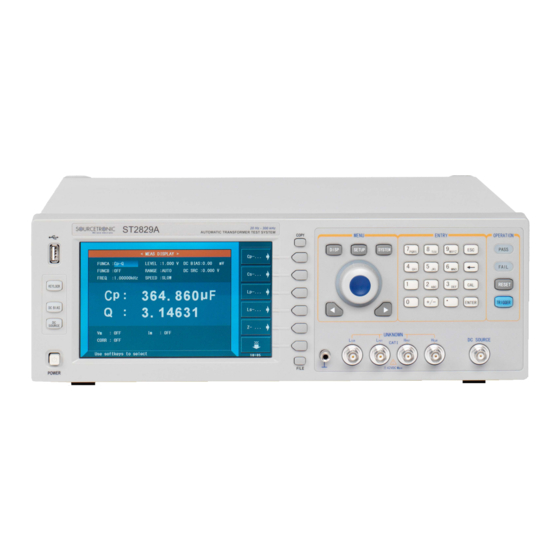
ST2829. ST2829 series instrument includes ST2829A, ST2829B and ST2829C. There frequency ranges are respectively 20Hz-300KHz, 20Hz-500KHz and 20Hz-1MHz. This manual takes ST2829A for example to describe the basic operation of T2829 series. 2.1 Introduction to front panel Figure 2-1 shows the front panel of ST2829. - Page 11 ST2829 Series Operation Manual Chapter 2 Introduction 6) LCD 800*480 colorful TFT LCD displays measurement results and conditions. 7) [COPY] Copy the currently displayed page to USB memory. 8) [DISP] Press this key to enter into the corresponding measurement display page of instrument functions.
-
Page 12: Introduction To Rear Panel
ST2829 Series Operation Manual Chapter 2 Introduction 22) Knob for menu selection and numeric input This knob is used to move the cursor, select and set parameters. 23) Confirmation key This key is used to end the data input, confirm and save the data input through knob. -
Page 13: Introduction To Display Zone
ST2829 Series Operation Manual Chapter 2 Introduction 6) IEEE-488 interface The tester can communicate with PC through GPIB interface. 7) RS232 interface Series communication interface can realize the communication with PC. 8) Fan window Heat elimination, maintaining the normal working temperature 9) Power socket Input AC power. -
Page 14: Main Menu Keys And Corresponding Displayed
ST2829 Series Operation Manual Chapter 2 Introduction 1) Display page name Indicate the name of the currently displayed page. 2) Soft keys The zone is used to display the function definition of soft key. The definition of soft key can be different as the difference of cursor’s direction in the zone. 3) Test result/ condition display zone In this zone, test result information and current condition are displayed. -
Page 15: Basic Operation
Press the power switch at the left corner on the front panel and then a boot screen will appear which displays our company logo, instrument model (ST2829A), and the version number of the software (Ver1.0.0). - Page 16 ST2829 Series Operation Manual Chapter 2 Introduction If the password protection function is on, users are required to input the password and then press [ENTER] to enter into the page of main menu. ——————————————————————————————————————— Note: The instrument has a default password-2829. In your practical use, you can change it and set your own one.
-
Page 17: Chapter 3 Introduction To [Disp]
ST2829 Series Operation Manual Chapter 3 Introduction to [DISP] Chapter 3 Introduction to [DISP] 3.1 <MEAS DISPLAY> When the LCR function is applied, press [DISP], the <MEAS DISPLAY> page will be displayed on screen as shown in the following figure. ST2829-301 On this page, the test result is displayed in upper-case character. -
Page 18: Test Function
ST2829 Series Operation Manual Chapter 3 Introduction to [DISP] 3.1.1 Test function In a measurement period, ST2829 can test four parameters for an impedance component: two primary parameters and two secondary parameters. Parameters that can be tested are as follows: Primary parameters |Z| (Module of impedance) ... - Page 19 ST2829 Series Operation Manual Chapter 3 Introduction to [DISP] Cs-Q Cs-Rs ← Press the soft key corresponding to your desired parameter. Then press ← to return to upper soft key menu. 4) Press Lp—…→, the following parameters will be shown for your choice. Lp-D ...
-
Page 20: Test Range
“---”. Operation steps for setting test frequency: ST2829A provides two methods to set measurement frequency. The first one is to use soft keys and the other one is to input data by using numeric keys. 1) Move the cursor to the FREQ zone, the following soft keys will be displayed. -
Page 21: Test Level
ST2829 Series Operation Manual Chapter 3 Introduction to [DISP] 20 Hz 100 Hz 1 kHz 10 kHz 100 kHz 1MHz 25 Hz 120 Hz 1.2 kHz 12 kHz 120 kHz 30 Hz 150 Hz 1.5 kHz 15 kHz 150 kHz 40 Hz 200 Hz 2 kHz 20 kHz 200 kHz... -
Page 22: Dc Bias
ST2829 Series Operation Manual Chapter 3 Introduction to [DISP] This soft key is used to increase the level of test signal source. ↓(-) This soft key is used to decrease the level of test signal source. 2) Soft or numeric keys are used to select or set the test level. When numeric keys are used to input the desired level, the available units (mV, V, µA, mA and A) will be displayed in the soft key zone. -
Page 23: Tools
ST2829 Series Operation Manual Chapter 3 Introduction to [DISP] Measurement delay (from startup to the start of measurement) Display time of test results You can select test mode as FAST, MED or SLOW. Generally, the test result is more stable and accurate in SLOW test mode. -
Page 24: Save Lcr Test Result By U Disk
ST2829 Series Operation Manual Chapter 3 Introduction to [DISP] 3.1.8 Save LCR test result by U disk Users can use U disk to save LCR test result. The following test results and the saving format can be stored in U disk. 1) COMP-ON: FUNCA, primary parameter, secondary parameter, status (0 means normal), sorting result COMP-OFF: FUNCA, primary parameter, secondary parameter, status (0... -
Page 25: Comparator Function
ST2829 Series Operation Manual Chapter 3 Introduction to [DISP] ST2829302 The following control parameters can be set on <BIN NO. DISP>. Compare function ON/OFF (COMP) There are 2 zones: BIN NO. DISP, COMP. Their detailed information will be introduced as below. The following test conditions are displayed in the measurement result/condition zone. -
Page 26: Bin Count Disp
ST2829 Series Operation Manual Chapter 3 Introduction to [DISP] system and further realizing auto-sorting test. These limits can only be set on the <LIMIT TABLE SETUP> page. Users can set the compare function to ON or OFF in the COMP zone. Operation steps for compare function 1) Move the cursor to COMP, the following soft keys will be displayed. -
Page 27: Param
ST2829 Series Operation Manual Chapter 3 Introduction to [DISP] 3.3.1 PARAM Parameter zone shows the “Function” parameter, if user selects primary and secondary parameter swap compare mode, the parameter will be displayed as swap parameter, such as: “Cp-D” is displayed as “D-Cp”, which means the current D is compared as primary parameter while Cp is compared as secondary parameter. -
Page 28: List Sweep Disp
ST2829 Series Operation Manual Chapter 3 Introduction to [DISP] Press the soft key OFF to turn off the count function. 4) Press the soft key RESET, “☺ : Reset count, Sure?” will be displayed in the help zone. Then the following soft keys will be displayed. ... -
Page 29: Sweep Mode
ST2829 Series Operation Manual Chapter 3 Introduction to [DISP] 3.4.1 Sweep mode The list sweep function of ST2829 can make automatic sweep test for up to 10 points’ test frequencies, test levels or DC bias. Two sweep modes are available on ST2829: SEQ and STEP. -
Page 30: Trace Sweep>Page
ST2829 Series Operation Manual Chapter 3 Introduction to [DISP] 3.5 <TRACE SWEEP>page Press [DISP] and MEAS DISP, BIN NO. DISP, BIN COUNT, LIST SWEEP, TRACE SWEEP, SAVE DATA will be displayed on the screen. Choose TRACE SWEEP function to enter into the trace sweep page. ST2829 3-1 Within the user preset mode, automatic sweeping of the components and parts can be conducted in linearity or logarithm mode with the points of 101, 201, 401... -
Page 31: Scale
ST2829 Series Operation Manual Chapter 3 Introduction to [DISP] 3.5.2 SCALE This zone is used to adjust the display scale of the sweep curve. AUTO It can automatically adjust the display scale of the curve. HOLD Now, it will hold the current display scale. Users should manually set the parameter of A MIN, A MAX, B MIN and B MAX in <TRACE SWEEP SETUP>... -
Page 32: Measure Setup
ST2829 Series Operation Manual Chapter 3 Introduction to [DISP] ST2829 3-2 When the user selects the sweep parameter as frequency and impedance, the instrument will display the parameters of some ultrasound components, the detailed parameter is as below: Static capacitance value when C : 1kHz. - Page 33 ST2829 Series Operation Manual Chapter 3 Introduction to [DISP] ST2829306 In this page, the following control parameters can be set. (Items in parenthesis can be set) Test function (FUNCA) Test function (FUNCB) Test frequency (FREQ) Test level (LEVEL) ...
-
Page 34: Trigger Mode
ST2829 Series Operation Manual Chapter 3 Introduction to [DISP] Test function (FUNCB) Test frequency (FREQ) Test level (LEVEL) Test range (RANGE) Test speed (SPEED) DC Bias (DC BIAS) DC Voltage Source (DC SRC) 3.6.1 Trigger mode There are 4 trigger modes on ST2829: INT, MAN, EXT and BUS. -
Page 35: Bias Current Isolation Function
ST2829 Series Operation Manual Chapter 3 Introduction to [DISP] The range of constant voltage: 10 mV to 1 V The range of constant current: 100 µA to 10 mA ——————————————————————————————————————— NOTE: When the constant level function is valid, if the level exceeds above ranges, this function will be automatically set as OFF. -
Page 36: Average
ST2829 Series Operation Manual Chapter 3 Introduction to [DISP] 1) Move the cursor to ISO zone, the following soft keys will be displayed. 2) Press ON to turn on the bias current isolation function. 3) Press OFF to turn off the bias current isolation function. 3.6.4 Average The AVERAGE function can calculate the average value of two or more test results. -
Page 37: Delay Time
ST2829 Series Operation Manual Chapter 3 Introduction to [DISP] 3.6.6 Delay time ST2829 trigger delay means the delay time from triggering to test-start. Delay function can set the trigger delay time. When the list sweep test function is used, all set delay time will be delayed at each sweep test point. The range of the trigger delay time can be set from 0s to 60s with 1ms as the resolution. - Page 38 ST2829 Series Operation Manual Chapter 3 Introduction to [DISP] ΔABS (Absolute Deviation mode) The deviation currently displayed is the difference between the test value of the DUT and the preset reference value. The formula of calculating ΔABS is as below: ΔABS=X-Y Where, X is the test value of DUT...
-
Page 39: Correction
ST2829 Series Operation Manual Chapter 3 Introduction to [DISP] 3.7 <CORRECTION> Press [SETUP] to select CORRECTION to enter into the <CORRECTION> page. ST2829307 Open, short and load correction on the <CORRECTION> page can be used to eliminate distribution capacitance, spurious impedance other measurement errors. -
Page 40: Open
42 frequencies, the instrument can calculate all open correction data of different test ranges which corresponds to all test frequencies. Move the cursor to OPEN and then used ALL to execute full frequency open correction.(The highest test frequency of ST2829A is 300kHz) 20 Hz... -
Page 41: Short
ST2829 Series Operation Manual Chapter 3 Introduction to [DISP] 2) Connect test fixture to test terminal. The fixture is open and not connecting to any DUT. 3) Press ALL, ST2829 will test the open admittance (capacitance and inductance) under 41 frequencies. -
Page 42: Load
ST2829 Series Operation Manual Chapter 3 Introduction to [DISP] ranges. Move the cursor to the SHORT zone, and then use the ALL soft key to execute full frequency open correction. The 41 fixed frequencies are the same as that in open correction. ST2829 can set 3 short correction frequencies in the FREQ zone on the ... - Page 43 ST2829 Series Operation Manual Chapter 3 Introduction to [DISP] frequencies can be set in the setup zones of FREQ 1, FREQ 2 and FREQ 3. The standard reference values can be set in the setup zones of REF A and REF B. The standard test function must be set in the Func zone before setting standard reference value.
-
Page 44: Load Correction Test Function
ST2829 Series Operation Manual Chapter 3 Introduction to [DISP] result (R, X) of the short correction will be displayed in the help line (the bottom line). 12) Move the cursor to SHORT. 13) Press ON to perform the short correction calculation at preset frequency in latter measurements. -
Page 45: Limit Table
ST2829 Series Operation Manual Chapter 3 Introduction to [DISP] <LIMIT TABLE> Press [SETUP] and then LIMIT TABLE to enter into the <LIMIT TABLE SETUP> page as the following figure shown. ST2829308 Compare function can be set on this page. ST2829 can set 9 bin limits of primary parameters and one of secondary parameters. -
Page 46: Limit Modes Of Compare Function
ST2829 Series Operation Manual Chapter 3 Introduction to [DISP] function can change the test parameter as D-Cp. Then user can set 9 pairs of compare limits for D, but only 1 pair of compare limit can be set for Cp. Operation steps for the swap parameter function Execute the following operations to swap the primary and the secondary parameters. -
Page 47: Set Nominal Value Of Tolerance Mode
ST2829 Series Operation Manual Chapter 3 Introduction to [DISP] ——————————————————————————————————————— Note: When setting limit values of tolerance mode, the error range should be set in the order from small to large. If the error range of BIN1 is the largest one, then all DUT will sort into BIN 1. -
Page 48: Auxiliary Bin On/Off
ST2829 Series Operation Manual Chapter 3 Introduction to [DISP] it is used in the automatic sorting system, the compare function will be especially useful. Operation steps for setting the compare function ON/OFF 1) Move the cursor to COMP, the following soft keys will be displayed. ... -
Page 49: High/Low
ST2829 Series Operation Manual Chapter 3 Introduction to [DISP] 3.8.6 HIGH/LOW ST2829 can set bin limits of 9 primary parameters and one secondary parameter. The test results can be sorted into 10 bins at most (BIN 1 to BIN 9 and BIN OUT). The high/low limits of primary parameters can be set in high limit and low limit of bins from BIN 1 to BIN 9. -
Page 50: List Sweep Setup
ST2829 Series Operation Manual Chapter 3 Introduction to [DISP] 3.9 <LIST SWEEP SETUP> Press [SETUP] and then LIST SWEEP to enter into the <LIST SWEEP SETUP> page as shown below. ST2829309 The list sweep function of ST2829 can perform auto sweep test for the test frequency, test level or bias voltage of 10 points. -
Page 51: Sweep Parameter Setup
ST2829 Series Operation Manual Chapter 3 Introduction to [DISP] displayed. FREQ [Hz] LEVEL [V] LEVEL [A] BIAS [V] BIAS [A] 2) Press one of above soft keys to select the list sweep parameter. 3.9.3 Sweep parameter setup Move the cursor to the table to perform the setup of each sweep parameter: FREQ (HZ), LMT, HIGH and LOW. -
Page 52: Mode
ST2829 Series Operation Manual Chapter 4 [SYSTEM] and [FILE] ST2829 3-3 The display function page is used for the setup of trace sweep measurement parameters, including MODE, START, STOP and coordination range of primary and secondary parameter. 3.10.1 MODE “MODE” includes [Hz], level [V], level [A], bias [V], bias [A]. Operation:Move cursor to MODE and select corresponding softkey. -
Page 53: Start
ST2829 Series Operation Manual Chapter 4 [SYSTEM] and [FILE] ST2829 3-4 3.10.2 START Select the number you need on keyboard (0~9/+, -/.) and press enter key or select a corresponding unit. NOTE: when the cursor moves to “START”, “STOP”, “A MIN, A MAX, B MIN, B MAX”, “TRACE SWEEP”... -
Page 54: Chapter 4 [System] And
ST2829 Series Operation Manual Chapter 4 [SYSTEM] and [FILE] Chapter 4 [SYSTEM] and <FILE MANAGE> 4.1 <SYSTEM SETUP> Press [System] and then SYSTEM SETUP to enter into the <SYSTEM SETUP> page shown as below. ST2829401 On this page, most system setup items are displayed, such as instrument main function, beeper, PASS beeper, FAIL beeper, language, PASS word, bus mode, GPIB address, TALK only, Bias SRC, baud rate, data/time. -
Page 55: Pass Beep
ST2829 Series Operation Manual Chapter 4 [SYSTEM] and [FILE] MASTER This soft key is used to select the instrument as the beeper source. SCANNER This soft key is used to select the scanner as the beeper source. This soft key is used to select both the instrument and the scanning box as the beeper source. -
Page 56: Language
ST2829 Series Operation Manual Chapter 4 [SYSTEM] and [FILE] This soft key is used to select two low and short beeps. This soft key is used to set the fail beep mode OFF. ——————————————————————————————————————— Note: In scanning box, the potentiometer is used to adjust the volume, so when selecting SCANBOX as the beep source, you can only control the beep to be long and short but not high and low. -
Page 57: Bus Mode (Reserved Function)
ST2829 Series Operation Manual Chapter 4 [SYSTEM] and [FILE] 4.1.7 BUS MODE (Reserved function) This mode is used to select RS232C, GPIB, LAN, USBTMC or USBCDC. Operation steps for setting bus mode 1) Move the cursor to Bus, the following soft keys will be displayed. RS232C ... -
Page 58: Baud Rate
ST2829 Series Operation Manual Chapter 4 [SYSTEM] and [FILE] The standard DC bias voltage source is from -10V to +10V and the DC bias current source is from 0 to 100mA. ——————————————————————————————————————— NOTE: When the DC bias source is in use, only the output impedance of 100Ω can be used. -
Page 59: Lcr
ST2829 Series Operation Manual Chapter 4 [SYSTEM] and [FILE] 4.2 LCR <FILE MANAGE> ST2829 series instrument can save the user-set parameter to the nonvolatile memory in the form of file, so when use the same setting next time user can load a corresponding file to obtain the parameter set and used last time. -
Page 60: U-Disk Manage Performance
ST2829 Series Operation Manual Chapter 4 [SYSTEM] and [FILE] DELAY Rsou DEV A DEV B REF A REF B Control and set parameters on <BIN COUNT DISP> page BIN COUNT (ON/OFF) ... - Page 61 ST2829 Series Operation Manual Chapter 4 [SYSTEM] and [FILE] 1) Roll the knob to view one by one. 2) Use the [←] and [→] to view one page by one page. 3) Press the soft key FIND. Input the file name and then press the [ENTER] to search the target file.
- Page 62 ST2829 Series Operation Manual Chapter 4 [SYSTEM] and [FILE] 2) Press FILE MANAGE, the file list and the following soft keys will be displayed. LOAD SAVE COPY to E: FIND 3) Move the cursor the file to be copied and press [ENTER] to confirm. 4) Press COPY to E: to copy the file the instrument.
-
Page 63: Chapter 5 Execute Lcr Operation And Some Examples
ST2829 Series Operation Manual Chapter 5 Execute LCR Operation and Some Examples Chapter 5 Execute LCR operation and some examples 5.1 Correction operation To execute correction operation (in order to prevent the stray impedance from affecting the test accuracy, it is necessary to make open/short correction), users can select one of the two correction modes. -
Page 64: Point-Frequency Correction
ST2829 Series Operation Manual Chapter 5 Execute LCR Operation and Some Examples 5.1.2 Point-frequency correction This function will gain better results in single-frequency test. If the test frequency is 5.5kHz, a) Press the menu key [SETUP] and then CORRECTION, then instrument will display the <CORRECTION>... -
Page 65: Eliminate The Influence Of Stray Impedance
ST2829 Series Operation Manual Chapter 5 Execute LCR Operation and Some Examples tested impedance (for example: R <Z /1000, the accuracy error is required to lead be less than 0.1%), before connecting to DUT, it is recommended to connect Hcur, Hpot and Lpot, Lcur (Two terminal test). -
Page 66: Operation Example For Testing Inductance With St2829A
By this way, the magnetic fields produced by these currents can be mutually offset and further eliminate the influence of mutual inductance coupling on test results. 5.4 Operation example for testing inductance with ST2829A Test Condition Function: Ls-Q Frequency: 5.5kHz... - Page 67 Press 100Ω to select 100Ω as the signal internal impedance. 3) Connect the test fixture (ST26005) to the test terminals of ST2829A. 4) Execute correction (To avoid the influence of stray impedance on measurement accuracy, Open/ Short correction must be operated) (refer to 5.1.2 “Point-frequency correction”)
-
Page 68: Operation Example Of Testing Capacitance By Multi-Frequency List Sweep
ST2829 Series Operation Manual Chapter 5 Execute LCR Operation and Some Examples ST2829501 7) If the test result is obviously incorrect, please check the following items. a) Check the tested inductance is in good connection with the test fixture or not. b) Check the test fixture is in good connection with the test terminals of the instrument or not. - Page 69 ST2829 Series Operation Manual Chapter 5 Execute LCR Operation and Some Examples 2) Set basic parameters. a) Press [DISP] to enter into the <MEAS DISP> page. b) The FUNC zone is currently displayed as Cp-D and the Level zone is 1.000V.
- Page 70 ST2829 Series Operation Manual Chapter 5 Execute LCR Operation and Some Examples information zone and the soft key zone will display the following available units: p, n, μ, m and k. Press ENTER, this zone will be changed as 300.000μ and the cursor will automatically move to the parameter zone of sweep point 3.
-
Page 71: Operation Example Of Load Correction
ST2829 Series Operation Manual Chapter 5 Execute LCR Operation and Some Examples correction function should be set as OFF. Refer to Correction operation in this chapter. 5.6 Operation example of load correction 1) Operation steps Test condition Frequency: 100kHz Cp: 11nF D: 0.0005 a) Press [SETUP], the following soft keys will be displayed in the soft key zone: MEAS SETUP, CORRECTION, LIMIT SETUP, SWEEP SETUP, FILE MANAGE and... - Page 72 ST2829 Series Operation Manual Chapter 5 Execute LCR Operation and Some Examples interference source be far away from the test fixture. Press the soft key Open to execute open correction. Insert the short plate (ST26010) into the test fixture. Please ensure that the short plate and the reeds of the test fixture have good contact.
-
Page 73: Chapter 6 Performance And Test
ST2829 Series Operation Manual Chapter 6 Performance and Test Chapter 6 Performance and Test 6.1 Test function 6.1.1 Parameter and symbol C:capacitance L:Inductance R:resistance Z:impedance Y:Admittance X:reactance B:susceptance G:Conductance D:dissipation θ:phase angle Q:Quality factor Lk: leakage inductance DCR: DC resistance Test combination Parameters described above are combined in the following modes: Primary parameter... -
Page 74: Delay Time
Delay time: time from trigger to start. 0 to 60s are programmable with a resolution of 1ms. 6.1.7 Connection modes of test terminals ST2829A adopts 4-terminal test method. HD(Hcur): current sample high terminal LD(Lcur): Current sample low terminal HS(Hpot):voltage sample high terminal LS(Lpot): Voltage sample low terminal 6.1.8 Test speed (Frequency>=10kHz) -
Page 75: Signal Mode
ST2829 Series Operation Manual Chapter 6 Performance and Test 6.2.2 Signal mode Normal: When testing, on measurement display page, voltage across test terminals may be smaller than preset voltage. Constant level: The auto adjustment of internal level makes the voltage of DUT accordant with preset voltage. -
Page 76: Dc Bias Voltage Source
ST2829 Series Operation Manual Chapter 6 Performance and Test 6.2.7 DC bias voltage source 0V— ± 10V Minimum resolution: 0.5mV, Accuracy: 1% x preset voltage+5mV 0mA—± 100mA Minimum resolution: 5μA 6.3 Measurement accuracy Test accuracy includes stability、temperature coefficient、linear degree、test repeatability and calibration inter-error. Check the accuracy of instrument should be under the following circumstances:... -
Page 77: Accuracy Of Q
ST2829 Series Operation Manual Chapter 6 Performance and Test 6.3.3 Accuracy of Q The accuracy of Q is given by the formula below: × ± × Where,Q is the value of the tested Q. is the accuracy of D Above formula should be used when Q ×D <1. -
Page 78: The Accuracy Of Rs
ST2829 Series Operation Manual Chapter 6 Performance and Test 6.3.7 The accuracy of Rs when D (value of tested D)≤0.1 The accuracy of R is given by the formula below: ×D [Ω] = 2πfL π Where, X is the value of test X with the unit [S]. is the value of test C with the unit [F]. - Page 79 ST2829 Series Operation Manual Chapter 6 Performance and Test In figure A, select a smaller value on boundary line. (This figure is the basic accuracy for 2829A. The basic accuracy for 2829B 300kHz-500kHz is about thousandth, while the basic accuracy for 2829C 500kHz-1MHz is about hundredth) In this figure, the basic accuracy value A can be obtained by the following methods:...
- Page 80 ST2829 Series Operation Manual Chapter 6 Performance and Test modification coefficient A (refer to figure B), the current basic measurement accuracy A is obtained by multiplying A got in step 1 with A Figure B is the basic accuracy modification curve, where V is the test signal voltage.
-
Page 81: Accuracy Of Dcr
ST2829 Series Operation Manual Chapter 6 Performance and Test Table B calibrated interpolating factor K Test frequency Direct calibrated frequency Other frequency 0.0003 Table C Direct Calibrated frequency [Hz] [Hz] [kHz] [kHz] [kHz] There are 43 frequencies in table C. Table D Cable length factor K Cable length Test signal level... -
Page 82: Insulation Resistance
ST2829 Series Operation Manual Chapter 6 Performance and Test 6.4.1 Insulation resistance Under reference working condition,the insulation resistance between power terminal and instrument jacket should not be smaller than50MΩ. Under humility condition, the insulation resistance between voltage terminal and instrument jacket should not be smaller than 2 MΩ. 6.4.2 Insulation intensity Under reference working condition, the insulation between the power terminal and the instrument jacket should bear an AC voltage (50Hz frequency and 1.5kV... -
Page 83: Function Check
Connect frequency meter to ground terminal. The test terminal of the frequency meter is connected with H Change the frequency as: 20Hz, 100Hz, 1kHz, CUR. 10kHz, 100kHz, 200kHz (ST2829A is 300kHz). The reading of frequency meter should meet the demand of the test signal frequency in this chapter. -
Page 84: Measurement Accuracy
ST2829 Series Operation Manual Chapter 6 Performance and Test 6.6.6 Measurement accuracy Basic parameters are R, L, C and D, so measurement accuracy is mainly about R, L, C and D. 6.6.7 Accuracy of C and D Function Test frequency 100Hz 1kHz 10kHz... -
Page 85: Accuracy Of Dcr
ST2829 Series Operation Manual Chapter 6 Performance and Test 6.6.10 Accuracy of DCR Test condition Function Test frequency ----- Level ----- Range AUTO Bias ----- Speed Slow Short correction should be made before testing. Connect standard DC resistors: 0.1Ω, 1Ω, 10Ω, 100Ω, 1kΩ, 10kΩ, 100kΩ. The error between reading and nominal value should be in the range ruled in this chapter. -
Page 86: Chapter 7 Command Reference
ST2829 Series Operation Manual Chapter 7 Command Reference Chapter 7 Command Reference The signs in this manual are as follows: NR1: integer, e.g.:123 NR2: fix-point number, e.g.: 12.3 NR3: floating-point number, e.g.: 12.3E+5 NL: carriage key, ASCII code: 10 ˆEND: EOI signal in IEEE-488 7.1 Subsystem commands for ST2829 ●DISPlay ●FREQuency... - Page 87 ST2829 Series Operation Manual Chapter 7 Command Reference DISPlay :PAGE MEASurement BNUMber BCOunt LIST MSETup CSETup LTABle LSETup SYSTem FLISt TTSe TLSet TMDisp TJDisp TSDisp :LINE “<string>” :RFONt LARGe TINY The :PAGE command sets the display page. The :DISPlay:PAGE? query returns the current page. Command syntax: DISPlay:PAGE<page name>...
-
Page 88: Frequency Subsystem Commands
ST2829 Series Operation Manual Chapter 7 Command Reference <page name> can be set as the following items: <LCR MEAS DISP> The current page is the LCR measurement display page. <BIN No. DISP> The current page is the bin number display page. <BIN COUNT DISP>... -
Page 89: Voltage Subsystem Commands
NR1, NR2 or NR3 data format followed by Hz, kHz, MHz. Set the measurement frequency as 20Hz. Set the measurement frequency as 200kHz (The maximum frequency of ST2829A is 300kHz) For example: WrtCmd(“FREQ 1KHZ”) Set the frequency as 1000Hz. Query syntax: FREQuency? Return format: <NR3><NL^END>... -
Page 90: Amplitude Subsystem Commands
ST2829 Series Operation Manual Chapter 7 Command Reference For example: WrtCmd (“CURR 10MA”) Set the measurement current as 10mA. Query syntax: CURRent? Return format:<NR3><NL^END> 7.1.5 AMPLitude subsystem commands The :AMPLitude subsystem commands are mainly used to set the auto level control (ALC) function as ON or OFF. - Page 91 ST2829 Series Operation Manual Chapter 7 Command Reference Command tree: OUTPut :High POWer ON(1) (valid only when ST2901-1A is installed) OFF(0) :ISOLation ON (1) OFF (0) The :HPOWer command is used to set the 1A DC bias source as ON or OFF. The :HPOWer? query returns the current status of the 1A DC bias source.
-
Page 92: Bias Subsystem Commands
ST2829 Series Operation Manual Chapter 7 Command Reference Query syntax: OUTPut:DC:ISOLation? Return format: <NR1><NL^END> 7.1.8 BIAS subsystem commands The :BIAS subsystem commands are mainly used to set the internal bias voltage and the bias status. Command tree: BIAS :STATe ON (1) OFF (0) :VOLTage <value>... -
Page 93: Function Subsystem Commands
ST2829 Series Operation Manual Chapter 7 Command Reference Set the bias voltage as 10V. For example: WrtCmd (“BIAS:VOLT MIN”) Set the DC bias voltage as 0V. Query syntax: BIAS:VOLTage? Return format: <NR3><NL^END> The BIAS:CURRent (only GPIB interface) command is used to set the external bias current. - Page 94 ST2829 Series Operation Manual Chapter 7 Command Reference FUNCtion :IMPedance CPRP CSRS LPRP LSRS :RANGe <value> :AUTO ON (1) OFF (0) :Source MONitor :VAC ON (1) OFF (0) :IAC ON (1) OFF (0) :DEV1 :MODE ABSolute PERcent :REFerence <value> :FILL The FUNCtion:IMPedance command is used to set instrument functions.
- Page 95 ST2829 Series Operation Manual Chapter 7 Command Reference Set the function as Cp-G Set the function as Ls-Q CPRP Set the function as Cp-Rp LSRS Set the function as Ls-Rs Set the function as Cs-D Set the function as R-X ◦...
- Page 96 ST2829 Series Operation Manual Chapter 7 Command Reference voltage monitor status. ON (1) FUNCtion:SMONitor:VAC OFF (0) Where, Character 1 (49) is equal to ON. Character 0 (48) is equal to OFF. For example: WrtCmd (“FUNC:SMON:VAC ON”) Set the voltage monitor as ON. Query syntax: FUNCtion:SMONitor:VAC? Return format: <NR1><NL^END>...
-
Page 97: List Subsystem Commands
ST2829 Series Operation Manual Chapter 7 Command Reference PERC <NL^END> The FUNCtion:DEV<n>:REFerence<value> command is used to set the nominal value of the deviation. The FUNCtion:DEV<n>:REFernece<value>? query returns the current nominal value of the deviation. Command syntax: FUNCtion:DEV<n>:REFerence<value> Where, <value> is NR1, NR2 or NR3 data format. <n>... - Page 98 ST2829 Series Operation Manual Chapter 7 Command Reference The LIST:FREQuency command is used to clear the original sweep points and set the frequencies of the sweep points. The LIST:FREQuency? query returns the current frequency of each sweep point. Command syntax: LIST:FREQuency<value>[,<value>*] NOTE: * part means 10 sweep points at most can be set.
- Page 99 ST2829 Series Operation Manual Chapter 7 Command Reference NOTE: * part means 10 sweep points at most can be set. Where, <value> is NR1, NR2 or NR3 data format. For example: WrtCmd (“LIST:CURR 100MA”) Set the measurement current of the sweep point 1 as 100mA. WrtCmd (“LIST:CURR 1E-2, 2E-2, 3E-2, 4E-2”) Set the currents of sweep points 1, 2,3 and 4 respectively as 10mA, 20mA, 3mA and 4mA.
-
Page 100: Aperture Subsystem Commands
ST2829 Series Operation Manual Chapter 7 Command Reference bias current source. If 1A DC source is required, please install an external source. ST2829 can be used with ST1773 DC Bias Source (providing DC current from 0 to 10A and can be bought from our company). -
Page 101: Trigger Subsystem Commands
ST2829 Series Operation Manual Chapter 7 Command Reference current measurement speed, average times. Command syntax: FAST APERture MEDium [,<value>] SLOW Where, FAST: 30 times/sec MEDium: 10 times/sec SLOW: 2 times/sec <value> 1 to 255 in NR1 For example: WrtCmd (“APER MED, 55”) Query syntax: APERture? Return format: FAST... -
Page 102: Fetch? Subsystem Commands
ST2829 Series Operation Manual Chapter 7 Command Reference HOLD Where, INTernal The default trigger mode. EXTernal Triggered by HANDLER interface. Triggered by RS232C interface or GPIB interface HOLD Triggered by pressing TRIGGER. For example: WrtCmd (“TRIG:SOUR BUS”) Query syntax: TRIGger:SOURce? Return format: <NL^END>... - Page 103 ST2829 Series Operation Manual Chapter 7 Command Reference The FETCh[:IMP]? query directs ST2829 to input the last measurement result to the output buffer zone. Query syntax: FETCh[:IMP]? For example: WrtCmd (“TRIG:SOUR BUS”) WrtCmd (“TRIG”) WrtCmd (“FETC?”) ST2829 applies ASCII to delivery result, details are follows. On measurement display page, bin NO.
-
Page 104: Correction Subsystem Commands
ST2829 Series Operation Manual Chapter 7 Command Reference Bin 7 Bin 8 Bin 9 Auxiliary bin <Bin No.> format: The data displays the sorting results of the displayed bin, shown as above. Only when the instrument compare function is set as ON, <bin No.> data can be displayed. - Page 105 ST2829 Series Operation Manual Chapter 7 Command Reference CORRection :LENGth <value> :MESTod SINGle MULTiple :OPEN :STATe ON (1) OFF (0) :SHORt :STATe ON (1) OFF (0) :LOAD :STATe ON (1) OFF (0) :TYPE CPRP CSRS LPRP LSRS :SPOT1 :STATe ON (1) OFF (0) :FREQuency <value>...
- Page 106 0 (decimal 48) is equal to OFF. For example: WrtCmd (“CORR:OPEN: STAT ON”) Query syntax: CORRection:OPEN:STATe? Return format: <NR1><NL^END> The CORRection:SHORt command is used to execute short correction for 43 preset test points (ST2829A has 41 preset test points). Command syntax: CORRection:SHORt For example: WrtCmd (“CORR:SHOR”)
- Page 107 ST2829 Series Operation Manual Chapter 7 Command Reference The CORRection:SHORt:STATe command is used to set the short correction status. The CORRection:SHORt:STATe? query returns the current short correction status. Command syntax: CORRection:SHORt:STATe Where, 1 (decimal 49) is equal to ON. 0 (decimal 48) is equal to OFF. For example: WrtCmd (“CORR:SHOR:STAT ON”) Query syntax: CORRection:SHORt:STATe? Return format: <NR1><NL^END>...
- Page 108 3 refers to frequency spot 3. For example: WrtCmd (“CORR:SPOT1:FREQ 2KHZ”) Set the frequency of frequency spot 1 as 2KHZ. NOTE: <value> should be ranged from 20HZ to 300KHZ (ST2829A), or return format will report errors. Query syntax: CORRection:SPOT<n>:FREQuency? Return format: <NR3><NL^END>...
- Page 109 ST2829 Series Operation Manual Chapter 7 Command Reference The CORRection:SPOT<n>:OPEN command is used to execute open correction for specific frequency spots (frequency 1, frequency 2 and frequency 3). Command syntax: CORRection:SPOT<n>:OPEN Where, <n>: 1 refers to frequency spot 1. 2 refers to frequency spot 2. 3 refers to frequency spot 3.
-
Page 110: Comparator Subsystem Commands
ST2829 Series Operation Manual Chapter 7 Command Reference channel number. Command syntax: CORRection:USE <channel number> Where, <channel number> ranges from 1 to 127 (NR1, NR2 or NR3 data format). For example: WrtCmd (“CORR:USE 10”) Set the channel number as 10. Query syntax: CORRection:USE? Return format: <channel number><NL^END>... - Page 111 ST2829 Series Operation Manual Chapter 7 Command Reference COMParator [:STATe] ON (1) OFF (0) :MODE Absolute TOLerance Percent TOLerance SEQuence :TOLerance :NOMinal <value> :BIN<n> <low limit>,<high limit> :SEQuence :BIN <BIN1 low limit>,<BIN1 high limit>, <BIN2 high limit>,<BIN3 high limit>, …… ,<BINn high limit> :Secondary LIMit <low limit>,<high limit>...
- Page 112 ST2829 Series Operation Manual Chapter 7 Command Reference ATOLerance COMParator:MODE PTOLerance SEQuence Where, ATOLerance means absolute tolerance mode. PTOLerance means proportional tolerance mode. SEQuence means sequential tolerance mode. For example: WrtCmd (“COM:MODE ATOL”) Query syntax: COMParator:MODE? Return format: ATOL PTOL <NL^END>...
- Page 113 ST2829 Series Operation Manual Chapter 7 Command Reference The COMParator:SEQuence:BIN command is used to set the high and the low limits of sequential mode (this function is valid only when the limit mode is set as the sequential mode.). The COMParator:SEQuence:BIN? query returns the current high and the low limits of each bin.
- Page 114 ST2829 Series Operation Manual Chapter 7 Command Reference For example: WrtCmd (“COMP:ABIN ON”) Query syntax: COMParator:Auxiliary BIN? Return format: <NR1><NL^END> The COMParator:SWAP command is used to set the swap mode ON or OFF. For example: the original function parameter is Cp-D, after the SWAP mode is set as ON, the function parameter will be changed as D-Cp.
- Page 115 ST2829 Series Operation Manual Chapter 7 Command Reference Query syntax: COMParator:BIN:COUNt[STATe]? Return format: <NR1><NL^END> The COMParator:BIN:COUNt:DATA? query returns the current comparison result of the bin count. Query syntax: COMParator:BIN:COUNt:DATA? Return format: <BIN1 count>, <BIN2 count>, …, <BIN9 count>, <OUT OF BIN count>, <AUX BIN count><NL^END>...
- Page 116 The *IDN? query returns ST2829 ID. Query syntax: *IDN? Return format: <manufacturer>,<model>,<firmware><NL^END> Where, <manufacturer> Name of Manufacturer ( Sourcetronic) <model> Instrument Model (ST2829A) <firmware> Firmware Version (VER1.0.0) For example: WrtCmd(“*IDN?”); The *TST? query executes an internal self test and returns the test result as ...
- Page 117 ST2829 Series Operation Manual Chapter 7 Command Reference Device Dependent Error(DDE) Bit Query Error(QYE) Bit Request Control(RQC) Bit Operation Complete(OPC) Bit Query syntax: *ESE? Return format: <value><NL^END> For example: WrtCmd (“*ESE?”) The *SRE (Service Request Enable command)command sets each open bit ...
- Page 118 ST2829 Series Operation Manual Chapter 7 Command Reference For example: WrtCmd (“*ESR?”) The *STB? query returns contents of the standard service status byte register. The execution of this command will not affect contents of the standard status byte register. Query syntax: *STB? Return format: <value><NL^END>...
- Page 119 SOURCETRONIC GMBH Fahrenheitstrasse 1 28359 Bremen Germany T +49 421 2 77 99 99 F +49 421 2 77 99 98 info@sourcetronic.com www.sourcetronic.com skype: sourcetronic www.sourcetronic.com...
Need help?
Do you have a question about the ST2829A and is the answer not in the manual?
Questions and answers
könnt ihr mir **** sagen warum wenn ich das Gerät St2829B nach dem ausschalten neu die sprache ändern muss wird die sprache chinesich was soll ich tun