
Related Manuals for Sourcetronic ST2516


Summary of Contents for Sourcetronic ST2516
- Page 1 SOURCETRONIC − Qualitäts-Elektronik für Service, Labor und Produktion Manual DC Resistance meter ST2516...
-
Page 2: Table Of Contents
ST2516 Series Operation Manual Contents Introduction to Instrument, Unpacking and Installing ............1 Introduction to Instrument................. 1 Unpacking ......................1 Power Connection ....................1 Fuse ........................2 Environment ....................... 2 Use of Test Fixture ....................2 Warm-up ......................3 Other Features ....................3 Introduction to Front and Rear Panels ................4... - Page 3 ST2516 Series Operation Manual 3.2.4 Compare Mode and SETTINGS of ABS & Percent Error ........13 <BIN DISP> ......................14 STATIS DISP ....................... 15 3.4.1 Edge Mode and Settings of Its Relevant Values ..........16 3.4.2 Status ON/OFF ....................16 3.4.3...
- Page 4 Install the Driver ....................36 USBCDC Virtual Serial Port ................37 6.3.1 System Configuration ..................37 6.3.2 Installing Driver ....................37 SCIP Command Reference ....................38 ST2516 Subsystem Commands ................. 38 7.1.1 DISPlay Subsystem Commands ................. 38 7.1.2 FUNCtion Subsystem Commands ..............39 Contents...
- Page 5 APERture Subsystem Commands ..............43 7.1.4 TRIGger Subsystem Commands ................ 43 7.1.5 FETCH? Subsystem Commands ................ 45 7.1.6 TEMPerature Subsystem Commands(ST2516) ..........46 7.1.7 COMParator Subsystem Commands ..............49 7.1.8 BIN Subsystem Commands ................52 7.1.9 STATistics Subsystem Commands ..............56 7.1.10...
- Page 6 ST2516 Series Operation Manual Declaration The descriptions contained in this manual may not cover all information about this instrument. Introductions to the improvements of the instrument in performance, function, internal structure, outer appearance, accessories, packing material, etc. are subject to change without notice. If you find any inconformity of this manual with our instruments, please contact us for further consultation by the address listed on the cover.
-
Page 7: Introduction To Instrument, Unpacking And Installing
ST2516 series is a powerful test tool for all kinds of resistor design, detection, quality control and production. Automation on production lines can be greatly improved by the realization of ultra-high test speed and the signal output of 3 compare results through HANDLER interface. -
Page 8: Fuse
ST2516 Series Operation Manual L (line wire), N (neutral wire) and E (earth ground wire) of the power supply input socket should correspond to the power plug of the instrument. The instrument has been specially designed for decreasing noise jamming caused by the input in AC power terminal, but it is also recommended to use it in the environment of low noise. -
Page 9: Warm-Up
ST2516 Series Operation Manual 1.7 Warm-up For accurate measurement, the warm-up time should not be less than 30 minutes. Do not turn on or off the instrument frequently. This may cause internal data confusion. 1.8 Other Features Consumption: ≤30VA Dimensions (W*H*D): 235mm*105mm*360mm; this dimension is the final packaging size. -
Page 10: Introduction To Front And Rear Panels
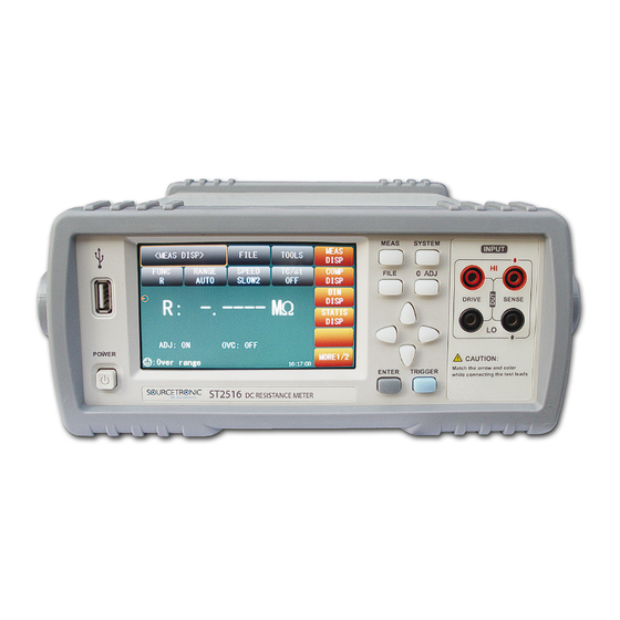
ST2516 Series Operation Manual 2) Introduction to Front and Rear Panels This chapter will describe the basic operation of ST2516. Before using the instrument, please read this chapter carefully. 2.1 Introduction to Front Panel Figure 2-1 shows the front panel of ST2516. -
Page 11: Introduction To Rear Panel
There are four arrow keys: up, down, left and right arrow keys. 11) Trademark and Model Show instrument trademark and model. 12) POWER It is the power switch. 2.2 Introduction to Rear Panel Figure 2-2 shows the rear panel of ST2516. RS-232C TEMP.INPUT RATING FUSE 110V/60Hz... -
Page 12: Display Zone
PC can remotely control ST2516 series through USB DEVICE. 2.3 Display Zone ST2516 series adopts 24-bit 4.3-inch LCD touch screen with a resolution of 480*272. The display screen is divided into the following zones, as shown in figure 2-3. Figure 2-3 Display zone Page name This zone shows the current page name. -
Page 13: Introduction To Buttons On Front Panel
ST2516 Series Operation Manual This zone displays all prompt information. Function zone This zone is used to change the measurement mode and measurement parameters. 2.4 Introduction to Buttons on Front Panel 2.4.1 [MEAS] Press <MEAS> to enter into display homepage. Selectable functions in this page are shown as follows: <MEAS DISP>... -
Page 14: Simple Operation
You can use arrow buttons to select a number or a letter. ST2516 touch screen operation is much easier. Just use your finger to touch the corresponding function on the screen and then the corresponding work will be done. -
Page 15: Basic Operation
ON: turn on the function of SHORT zero clearing (self-calibration function) OFF: turn off the function OVC (ON/OFF): compensation of the offset voltage, i.e. compensation of the measurement error due to thermoelectromotive force on the DUTs. (ST2516/ST2516A) 3.1.1 Measurement Functions Measurable parameters on ST2516 are as follows:... -
Page 16: Measurement Range
Measure and display two types of parameters: resistance parameters and temperature parameters. ST2516 has 9 DC resistance ranges: 20mΩ, 200mΩ, 2Ω, 20Ω, 200Ω, 2kΩ, 20kΩ, 200kΩ, 2MΩ ST2516A has 7 DC resistance ranges: 200mΩ, 2Ω, 20Ω, 200Ω, 2kΩ, 20kΩ, 200kΩ... -
Page 17: Measurement Speed
ST2516 Series Operation Manual Measurement Speed 3.1.3 ST2516 displays the measurement result as a 5-digit number in the decimal point floating mode. The measurement result of the speed is shown as a 4-digit number with one digit after the decimal point. -
Page 18: Comp Disp
ST2516 Series Operation Manual connected. If not, the deducted data will be wrong, and further it will cause result errors. The correct connection is shown as the following figure. 3.2 <COMP DISP> Touch <MEAS DISP> or press [MEAS] to select the COMP DISP soft key to enter into the <COMP DISP>... -
Page 19: File Manage
ST2516 Series Operation Manual 3.2.1 File Manage Touch FILE, the following soft keys will be displayed: File manage: Touch this soft key to enter into the file manage page. Screen copy: Touch this key to save the current screen page to a U disk. If no U disk is found, ... -
Page 20: Bin Disp
ST2516 Series Operation Manual tested values and the set ones so as to judge the DUT is HI or LO or IN. The set upper limit value should be equal or larger than the lower limit value. % (percent error) In this mode, you can set the nominal value and the percent error. -
Page 21: Statis Disp
ST2516 Series Operation Manual NG: Bin beep function is ON. When one of the bin comparator results is not consistent with the bin setting, the beep will sound. GD: Bin beep function is ON. When the bin comparator results are consistent with bin setting, the beep will sound. -
Page 22: Edge Mode And Settings Of Its Relevant Values
ST2516 Series Operation Manual value of results for multiple measurements, the PASS/FAIL rate and some engineering coefficients. Details are as below. 3.4.1 Edge Mode and Settings of Its Relevant Values Touch this key, two modes is available: ABS (high and low limits) and % (percent error mode). -
Page 23: Tools
ST2516 Series Operation Manual instrument buffer memory. : Upper limit value, used to be compared, corresponds to the value of UPPER limit. : Lower limit value, used to be compared, corresponds to the value of LOWER limit. When > 1.33, the working capacity is ideal. -
Page 24: Meas Setup
ST2516 Series Operation Manual status as OFF. 3.5 <MEAS SETUP> Touch the main menu. And then touch the soft key MEAS SETUP to enter into the MEAS SETUP page shown as figure 3-5. MEAS FILE <MEAS SETUP> SETUP TC/Δt FUNC... -
Page 25: Tc/∆T Setup> (St2516)
ST2516 Series Operation Manual ST2516B has no OVC function. 3.6 <TC/∆t SETUP> (ST2516) Touch the main menu. And then touch the soft key TC/∆t SETUP to enter into the TC/∆t setup page shown as figure 3-6. MEAS <TC/ΔT SETUP> FILE SETUP TC/Δt... -
Page 26: Temperature Conversion (∆T)
ST2516 Series Operation Manual NOTE: Before measurement, it is necessary to warm up the instrument and the probe for about half an hour. The temperature sensor should be placed to the DUT as close as possible but cannot contact it. After the displayed result comes to be stable, you can read or record the result. -
Page 27: Types Of Temperature Sensor
ST2516 Series Operation Manual Anti-corrosion alloy Nickel: 2.5 to 4.0 0.25 to 0.45 980 to 1770 Silicon: 0.5 to 1.0 Soft aluminum Aluminum>99.5 0.63 to 0.64 Hard-drawn Aluminum>99.5 0.60 to 0.62 aluminum Aluminum alloy Silicon: 0.4 to 0.6 0.50 to 0.55 Magnesium: 0.4 to... -
Page 28: Parameter Setting
ST2516 Series Operation Manual NOTE: V1 and V2 range from 00.00V to 02.00V while T1 and T2 range from -99.9℃ to 999.9℃. Parameter Setting 3.6.4 t0: Touch this key, the numeric keyboard will pop up and you can input the reference ... - Page 29 ST2516 Series Operation Manual Figure 3-7 Bin Setup On this page you can set all parameters concerned with the bin comparator. There are 3 groups of parameters (high and low limits, nominal value, %) can be set. The following parameters can be set on this page: BIN: Touch 1, 2, 3 below the bin, a Delete soft key will be displayed which can be used to ...
-
Page 30: System Setup And File Manage
ST2516 Series Operation Manual 4) System Setup and File Manage 4.1 System Setup Entering the system setup page, you can press [SYSTEM] or touch MORE2/2 on any display page to select system setup function as shown in figure 4-1. MEAS <SYSTEM SETUP>... -
Page 31: Password
ST2516 Series Operation Manual Touch this soft key to set the language as English. Chinese Touch this soft key to set the language as Chinese. You can touch soft keys to set corresponding functions. Password 4.1.3 The function is used to set the password. -
Page 32: Baud Rate
115200 AC Freq 4.1.6 ST2516 supplies two power supply frequencies: 50Hz and 60Hz. Please select the correct frequency so as to eliminate the influence of the power noise on the instrument. Handler VCC 4.1.7 Press the Handler VCC, the following six baud rates is selectable: ... -
Page 33: File Manage
Touch this key, the cursor under the time will move right. 4.2 <File Manage> ST2516 series can save parameters that are set by user to the internal non-volatile memory in the file format. User can load the file to use these parameters instead of resetting. - Page 34 U disk. If the U disk memory exceeds 512M, it is recommended to use FAT32 standard to format the disk. 3. Before a U disk is connected to ST2516, you are recommended to save the data on it and Sourcetronic will not be liable for the data loss.
- Page 35 ST2516 Series Operation Manual Operation Procedures Touch FILE in any page and select File Manage to enter into the internal file page (or directly press the FILE button on the front panel) as shown in below figure. Touch [Inter File] and [External File] to respectively display files stored in the internal FLASH and the external U disk.
- Page 36 U disk. Select Touch “Select”, the file the cursor locates will be selected. ST2516 can simultaneously copy several files to a U disk. Touch “Select” once again, the selected file will be cancelled from selection. Save Measurement Results In the “MEAS DISP”...
-
Page 37: Performance Index
5.1.1 R:Resistance T: Temperature LPR: Low current mode Measurement Groups 5.1.2 Five measurement groups are available: ST2516: R, R-T, T, LPR, LPR-T ST2516A, ST2516B: R, LPR Range 5.1.3 Range Mode: AUTO, MANU (HOLD, UP, DOWN) Trigger 5.1.4 Internal, Manual, External, BUS Internal: Continuously test a DUT and then output and display the result. -
Page 38: Resistance Measurement Time
Range from 1 to 255, programmable: this value reflects the measurement times from measuring resistance to measuring display. 5.2 Test Signal Current range 5.2.1 ST2516: Current range: 1μA -- 1A ST2516A: Current range: 10μA – 100mA ST2516B: Current range: 100μA -- 1A Output Voltage of Open Circuit 5.2.2 Output voltage of open circuit: 0.7V,... -
Page 39: Measurement Accuracy
ST2516 Series Operation Manual 5.3 Measurement Accuracy Checking the measurement accuracy should be taken under the following circumstances: a. Warm-up time should be more than 30 minutes. b. Correctly short the test cables, turn 0 ADJ to ON and perform short calibration by pressing the touch key or 0 ADJ panel. -
Page 40: Accuracy For Resistance Tested At Low Current Mode
ST2516 Series Operation Manual Resolution 1µΩ 10µΩ 100µΩ 1mΩ 10mΩ 100mΩ 1Ω Accuracy 0.1%+3 0.1%+2 Temperature 300ppm 100ppm coefficient Accuracy for Resistance Tested at Low Current Mode 5.3.2 ST2516, ST2516A, ST2516B Range 2Ω 20Ω 200Ω 2kΩ Current 10mA 100µA 10µA... -
Page 41: Remote Control
EIA in 1969, which rules to send one bit in a data line every time. As most serial interfaces, the serial interface of ST2516 is also not strictly based on RS-232 standard but only uses the smallest subset of this standard. The signals are listed in the following table. -
Page 42: Usbtmc Remote Control System
Install the Driver 6.2.2 When ST2516 is first connected to a PC through a USB cable, the prompt information –Found New Hardware will show on the right bottom of the computer desktop, as is shown below: Click “NEXT”, dialogue 6-11 will pop up. Choose “Install the software automatically (recommended)”. -
Page 43: Usbcdc Virtual Serial Port
When “USBCDC” is selected, the USB interface can be configured as a virtual serial port (VCom). System Configuration 6.3.1 Connect PC and ST2516 to the USB interface through a USB cable. Installing Driver 6.3.2 Methods of installing USBCDC driver are the same with that of installing USBTMC driver. When the installation of driver is finished, user can see “USB VCom Port”... -
Page 44: Scip Command Reference
ST2516 Series Operation Manual 7) SCIP Command Reference 1. Data Conventions of This Manual NR1 :integer, for example:123 NR2 :fixed number, for example: 12.3 NR3 :floating number, for example: 12.3E+5 NL :CR character,integer: 10 ^END:EOI (end) signal of IEEE-488 bus. -
Page 45: Function Subsystem Commands
ST2516 Series Operation Manual Set the display page to temperature setup. (ST2516) TSETup Set the display page to statistics. STATistics Set the display page to system setup. SYSTem Set the display page to (internal) file list. FLISt For example: WrtCmd(“DISP:PAGE MEAS”); Set the display page to basic measurement. - Page 46 The FUNCtion:IMPedance? query returns to the current “function” parameters. Command Syntax: FUNCtion:IMPedance <function> Details are as follows: Set “function” as R. Set “function” as R-T. (ST2516) Set “function” as T. (ST2516) Set “function” as LPR. LPRT Set “function” as LPR-T. (ST2516) For example: WrtCmd(“FUNC:IMP RT”);...
- Page 47 ST2516 Series Operation Manual resistance measurement pattern as 200Ω. Query syntax: FUNCtion:IMPedance: RES:RANGe? Return format: <value><NL^END> Where, <value> can be: ST2516:20.000E-3, 200.00E-3, 2000.0E-3, 20.000E+0, 200.00E+0, 2000.0E+0, 20.000E+3, 200.00E+3,2. 0000E+6 ST2516A: 200.00E-3, 2000.0E-3, 20.000E+0, 200.00E+0, 2000.0E+0, 20.000E+3, 200.00E+3 ST2516B:20.000E-3, 200.00E-3, 2000.0E-3, 20.000E+0, 200.00E+0, 2000.0E+0, 20.000E+3...
- Page 48 1: it indicates that the measured value of resistance exceeds 400 dgt, namely operation failed. The :OVC command sets the instrument offset voltage compensation state. The :OVC? Query returns to the current setstate.(ST2516/ST52516A) Command syntax: ON (1) :OVC OFF (0) Where, Character 1 (integer:49) means ON.
-
Page 49: Aperture Subsystem Commands
ST2516 Series Operation Manual <NR1> = 1 or 0 1: the offset voltage compensation state is “ON”. 0: the offset voltage compensation state is “OFF”. APERture Subsystem Commands 7.1.3 The APERture subsystem commands are mainly used to set the measurement speed and the average times used in measurement. - Page 50 ST2516 Series Operation Manual The :IMMediate command triggers a measurement. Command syntax: TRIGger[:IMMediate] For example:WrtCmd(“TRIG”); The :SOURce command sets the mode of trigger source. The :SOURce? query returns to the current mode of trigger source. Command syntax: TRIGger:SOURce <INTernal, MANual, EXTernal or BUS>...
-
Page 51: Fetch? Subsystem Commands
The FETCh? Subsystem commands are used to get the last measurement result and the setup of the mode. Command Tree: The [:IMP]? query returns ST2516’s last measurement result to its output buffer. Query syntax: FETCh[:IMP]? The data got from the commands can be divided into three types according to different functions and display page. -
Page 52: Temperature Subsystem Commands(St2516)
ST2516 Series Operation Manual <secondary parameter>= the measurement of the current secondary parameter and the format is NR3, when existing outrange or measurement error, the returned value is “+9.90000E+37”. The system status is the same as above. 3. There is no return value for other display page. - Page 53 ST2516 Series Operation Manual Query Syntax: :TEMPerature:CORRect:STATe? Return format: <NR1><NL^END> <NR1> = 1 or 0 1: the instrument temperature correction function is “ON”. 0: the instrument temperature correction function is “OFF”. The :TEMPerature:CORRect:PARameter command sets the “reference temperature” and “temperature coefficient” of the instrument temperature correction function.
- Page 54 ST2516 Series Operation Manual resistance” , ”initial temperature” and ”constant k”. Command syntax: :TEMPerature:CONversion:DELTa:PARameter<Initial resistance>,<Initial temperature>, <Constant> Where, < Initial resistance> = 0 to 110.000E+6(NR3) means “initial resistance”, unit: Ω < Initial temperature> = -10.0 to 99.9(NR2) means ”initial temperature”, unit: ℃...
-
Page 55: Comparator Subsystem Commands
ST2516 Series Operation Manual COMParator Subsystem Commands 7.1.7 COMParator subsystem commands are used to set the compare function of the insturment, including the setup of comparator switch, beeper mode, limit mode and other compare parameters. Command Tree: The :COMParator[:STATe] command sets the state of instrument comparator function. - Page 56 ST2516 Series Operation Manual IN :it beeps when the comparative result is qualified For example, WrtCmd(“:COMP:BEEP IN”); Set the comparator beeper mode as IN. Query Syntax: :COMParator:BEEPer? Return format: <OFF, HL or IN><NL^END> The :COMParator:MODE command sets the comparator limit mode of the instrument.
- Page 57 ST2516 Series Operation Manual Query Syntax: COMParator: LOWer? Return format: the format and unit of < Lower threshold ><NL^END> are the same as above. The :COMParator:REFerence command sets the reference resistance of the instrument comparator function. The :COMParator:REFerence? query returns to the current reference resistance.
-
Page 58: Bin Subsystem Commands
ST2516 Series Operation Manual The :COMParator: COUNter:STATe command sets the counter state of instrument comparator interface. The :COMParator: COUNter:STATe? query returns to the current counter state. Command syntax: :COMParator: COUNter :STATe <ON(1) or OFF(0)> For example, WrtCmd(“:COMP:COUN: STAT ON”); Set the counter function of the instrument comparator interface as “ON”. - Page 59 ST2516 Series Operation Manual Query Syntax: :BIN:STATe? Return format: <NR1><NL^END> <NR1> = 1 or 0 1: the current bin comparator function of the instrument is ”ON” 0: the current bin comparator function of the instrument is ”OFF” The :BIN:BEEPer command sets the beeper mode of the instrument bin comparator.
- Page 60 ST2516 Series Operation Manual For example: WrtCmd(“BIN:COLOr:NG GRAY”); Set the color of the result mark as GRAY when the bin comparator result is “NG”. Query Syntax: BIN:COLOr:NG? Return format: <OFF, GRAY, RED or GREEN><NL^END> The :BIN:COLOr:GD command sets the color of the display mark when the bin comparator result is “GD”.
- Page 61 ST2516 Series Operation Manual Command syntax: BIN: LOWer <Bin NO.>,< Lower threshold > Where, <Bin NO.> = 1 to 3(NR1) specified bin no., namely specific bin < Lower threshold > = 0 to 2.2E+6 (NR3) the lower threshold of the specific bin unit: “Ω”...
-
Page 62: Statistics Subsystem Commands
ST2516 Series Operation Manual BIN: ENABle <Enable Mask> Where, <Enable Mask> = 0 to 7(NR1) enable mask (decimal system) Transfer some bit to 1, namely hold the corresponding bin enable Bit No. BIN NO. BIN3 BIN2 BIN1 For example: WrtCmd(“BIN:ENAB 6”); Set the enable mask from BIN2 to BIN3. - Page 63 ST2516 Series Operation Manual The :STATistic [:STATe] command sets the statistics state of the instrument. The :STATistic [:STATe]? query returns to the current statistics state. Command syntax: : STATistics [:STATe] <ON(1) or OFF(0)> For example: WrtCmd(“:STAT:STAT ON”); Set the statistics function as “ON”.
- Page 64 ST2516 Series Operation Manual PTOLerance:set the limit mode of the instrument statistics function as proportional tolerance mode For example: WrtCmd(“STAT:MODE ATOL”); Set the limit mode of the instrument as absolute tolerance mode. NOTE: If the statistics function of the instrument is “ON”, ingore this command! Query Syntax: STATistics:MODE? Return format: <ATOL or PTOL><NL^END>...
- Page 65 ST2516 Series Operation Manual Where, < Reference Resistance > = 0 to 2.2E+6 (NR3) the reference resistance of the statistics function unit: “Ω” For example: WrtCmd(“STAT:REF 20E+3”); Set the reference resistance of the instrument statistics function as 20kΩ. NOTE: If the statistics function of the instrument is “ON”, ingore this command! Query Syntax: STATistics: REFerence? Return format: the format and unit of <...
- Page 66 ST2516 Series Operation Manual Return format: <Maximum (NR3), the corresponding data serial number of the maximum data (NR1)> NOTE: When the valid statistics numbers >= 1, it will returns to the valid value or “+9.90000E+37, 0”. For example: WrtCmd(“:STAT:MAX?”) Returned value: 1.2450E+01, 5 The : STATistics:MINimum command is used to query the minimum of the statistics results.
-
Page 67: System Subsystem Commands
ST2516 Series Operation Manual SYSTem Subsystem Commands 7.1.10 SYSTem subsystem commands are used to set the system function of the instrument, including the beeper switch, parameters save, output mode of measurement state error, parameter setting reset and so on. Command tree: The :SYSTem:BEEPer:STATe command sets the beeper switch state of the instrument. - Page 68 ST2516 Series Operation Manual The :SYSTem:SAVE command is used to save the current parameter setting. Command syntax: :SYSTem:SAVE <Table NO.1 to 30>, <File name> Where, <Table NO.1 to 30> = 1 to 30 (NR1), the serial number of file to be saved <File name>...
- Page 69 The *TRG command triggers the measurement and then sends the result to the output buffer. Command syntax: *TRG For example: WrtCmd(“*TRG”); NOTE: ”*trg” will be valid when :INIT:CONT ON and trig:sour bus commands are enabled. The *IDN? query returns ST2516’s identification string. Query syntax: *IDN? Return format: <manufacturer>,<model>,<firmware><NL^END> Where, <manufacturer>...
-
Page 70: Handler Interface
ST2516 Series Operation Manual 8) Handler Interface ST2516 DC Resistance Meter equips with a Handler interface which is mainly used to output the sorting result. When the instrument is applied to an automatic component sorting test system, this interface will output the handshake signal and the sorting result output signal. The sorting result output corresponds to the comparison result output of the current comparator bin. - Page 71 ST2516 Series Operation Manual Time Minimum value Maximum value t1: trigger pulse width t2: measurement time at one t3+t4 time t3: sampling time of one 1 Sampling Time measurement t4: data processing and display Display “ON”: 22ms time of one measurement Display “OFF”: 5ms...
-
Page 72: Package Contents And Warranty
ST2516 Series Operation Manual 9) Package Contents and Warranty 9.1 Package Contents Following items should be contained in the package. ST2516 series DC Resistance Meter ST26050A 4-terminal test cable Three-Wire power line PT500 Fuse of 2A Operation Manual Manufacturer Certificate... -
Page 73: Shipping
ST2516 Series Operation Manual 9.4 Shipping In the shipment, the instrument should be handled with care and some precautions must be taken to resist moisture and water. 9.5 Storage The instrument should be stored in an airy room where the environment temperature ranges from 5℃... - Page 74 SOURCETRONIC GMBH Fahrenheitstrasse 1 28359 Bremen Germany T +49 421 2 77 99 99 F +49 421 2 77 99 98 info@sourcetronic.com www.sourcetronic.com skype: sourcetronic www.sourcetronic.com...
Need help?
Do you have a question about the ST2516 and is the answer not in the manual?
Questions and answers