
Related Manuals for Sourcetronic ST2515


Summary of Contents for Sourcetronic ST2515
- Page 1 SOURCETRONIC − Quality electronics for service, lab and production User Manual DC Resistance Meter ST2515/A/B...
-
Page 2: Table Of Contents
ST2515 Operation Manual Contents Introduction to Instrument, Unpacking and Installing ............1 Introduction to Instrument................. 1 Unpacking ......................1 Power Connection ....................1 Fuse ........................2 Environment ....................... 2 Use of Test Fixture ....................2 Warm-up ......................2 Other Features ....................2 Introduction to Front and Rear Panels ................3... - Page 3 ST2515 Operation Manual 3.2.4 Compare Mode and SETTINGS of ABS & Percent Error ........13 <BIN DISP> ......................13 STATIS DISP ....................... 15 3.4.1 Edge Mode and Settings of Its Relevant Values ..........15 3.4.2 Status ON/OFF ....................15 3.4.3 Parameters of Statistic Analysis ...............
- Page 4 ST2515 Operation Manual 4.2.1 Introduction to Save/Recall ................30 4.2.2 Structure of File Folder/File in a U Disk ............30 <LAN SETUP> ....................34 4.3.1 DHCP ......................... 34 4.3.2 IP ADDR ......................35 4.3.3 SUBNET MASK ....................35 4.3.4 GATEWAY ......................35 4.3.5...
- Page 5 SCPI (Standard Commands for Programmable Instruments) ......46 LAN Remote Control System ................47 6.3.1 Accessing ST2515 through a Browser ............... 48 6.3.2 Access ST2515 through the Software on a controlling Computer ....49 USBTMC Remote Control System ..............49 6.4.1 System Configuration ..................49 6.4.2 Install the Driver ....................
- Page 6 ST2515 Operation Manual Handler Interface ......................84 Updates, Package Contents and Warranty ..............88 Firmware upgrading method: ................88 Package Contents ..................... 88 Marks ........................ 89 Package ......................89 Shipping ......................89 Storage ......................89 Warranty ......................89 Declaration The descriptions contained in this manual may not cover all information about this instrument.
-
Page 7: Introduction To Instrument, Unpacking And Installing
1.1 Introduction to Instrument ST2515 is a DC Resistance Meter with color LCD display and touch function. Its accuracy of 0.01% is able to meet general resistance test requirements. Better measurement result is obtained for temperature-sensitive resistors by the adoption of temperature compensation function. -
Page 8: Fuse
ST2515 Operation Manual 1.4 Fuse The fuse is a standard configuration, so use the included custom fuse please. 1.5 Environment Do not store or use the instrument where it could be exposed to many dusts, great vibration, direct sunshine and corrosive gas. -
Page 9: Introduction To Front And Rear Panels
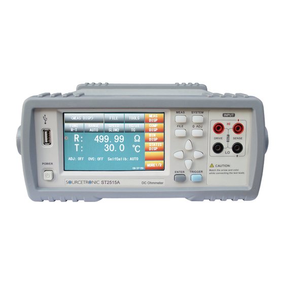
ST2515 Operation Manual 2) Introduction to Front and Rear Panels This chapter will describe the basic operation of ST2515. Before using the instrument, please read this chapter carefully. 2.1 Introduction to Front Panel Figure 2-1 shows the front panel of ST2515. -
Page 10: Introduction To Rear Panel
There are four arrow keys: up, down, left and right arrow keys. 11) Trademark and Model Show instrument trademark and model. 12) POWER It is the power switch. 2.2 Introduction to Rear Panel Figure 2-2 shows the rear panel of ST2515. GPIB RS-232C S/N: R5-211-00001 110V-240V... -
Page 11: Display Zone
Please refer to the introduction of HANDLER in Chapter 8 for specific information. 2.3 Display Zone ST2515 adopts 24-bit 4.3-inch LCD touch screen with a resolution of 480*272. The display screen is divided into the following zones, as shown in figure 2-3. -
Page 12: Introduction To Buttons On Front Panel
<SYSTEM SETUP> <LAN SETUP> <MEAS DISP> 2.5 Simple Operation Simple operation steps for ST2515: Use [MEAS], [SYSTEM] or [FILE] or soft keys to enter into the page required to enter. (Refer to figure 2-5) Use arrow buttons ([←] [↑] [→] [↓]) to move the cursor to desired zone. -
Page 13: Starting Up
Figure 2-4 shows the boot screen of ST2515, indicating product information such as instrument trademark, model and version. -
Page 14: Basic Operation
File manage (FILE) Other tools (TOOLS) Soft keys (used to enter into operation pages) 3.1.1 Measurement Functions Measurable parameters on ST2515 are as follows: R (Resistance) R-T (Resistance and temperature) T (Temperature) LPR (Resistance tested at low voltage) (ST2515A/2515B) ... -
Page 15: Measurement Range
Parameters of resistance range, current, resolution, etc. have been displayed in diagram 3-1-2. ST2515 has 11 DC resistance ranges: 20mΩ, 200mΩ, 2Ω, 20Ω, 200Ω, 2kΩ, 20kΩ, 100kΩ, 1MΩ, 10MΩ, 100MΩ. ST2515 has 4 DC low voltage resistance ranges: 2Ω, 20Ω, 200Ω, 2KΩ. -
Page 16: Measurement Speed
Operation steps for setting measurement speed: ST2515 displays the measurement result as a 6-digit number in the decimal point floating mode. In FAST mode, the result is shown as a 5-digit number while in MED and SLOW, as a 6-digit number and temperature as 4-digit. - Page 17 ST2515 Operation Manual 0 ADJ: Execute short correction. In this process, please ensure the test terminals have been correctly shorted. Only by doing this, unexpected measurement errors could be avoided. OVC (ON/OFF): ON is to use offset voltage compensation for measurement results. OFF is ...
-
Page 18: Comp Disp
ST2515 Operation Manual 3.2 <COMP DISP> Touch <MEAS DISP> or press [MEAS] to select the COMP DISP soft key to enter into the <COMP DISP> page shown as figure 3-2. Figure 3-2 The following parameters can be set on this page: FILE ... -
Page 19: Comp (On/Off)
ST2515 Operation Manual DATA STORAGE: Save all data. 3.2.3 COMP (ON/OFF) COMP (ON/OFF): ON indicates the compare function has been turned on. Only when the compare function is in ON mode, count function can be enabled. OFF is to turn off this function. - Page 20 ST2515 Operation Manual TOOLS DISP (ON/OFF): ON is to display the result while OFF is not to. SAVE DATA: Touch this key to save the result. Touch again to stop saving. BIN ON/OFF: ON is to turn on bin compare display while OFF is to turn off.
-
Page 21: Statis Disp
ST2515 Operation Manual 3.4 STATIS DISP Touch the main menu or press [MEAS]. And then touch the soft key STATIS DISP to enter into the STATIS DISP page shown as figure 3-4. Figure 3-4 Statistic display The function of this page is to count measurement data. It is workable to analyze the average value of results for multiple measurements, the PASS/FAIL rate and some engineering coefficients. -
Page 22: Parameters Of Statistic Analysis
ST2515 Operation Manual Parameters of Statistic Analysis 3.4.3 : Average value. Corresponding formula: : Population Standard Deviation. Corresponding formula: : Sample Standard Deviation. Corresponding formula: ... -
Page 23: Tools
ST2515 Operation Manual 3.4.4 TOOLS CLEAR: Clear all parameters obtained from last statistic. TRIGGER: Trigger the instrument to execute a measurement. SAVE DATA: Touch this key to save the current measurement result (not all statistic results) to ... - Page 24 ST2515 Operation Manual and BUS (BUS trigger mode). TRIG DELAY: Touch this key, the following soft keys will be displayed: AUTO, MANUAL, and INPUT. (NOTE: The setting time manually input should not be less than the DETECT time, or the instrument will prompt a message “Input number is over ranging.”)
-
Page 25: Tc/∆T Setup
ST2515 Operation Manual 0 ADJ (ON/OFF): Touch this key to select ON or OFF. ON is to turn on the short correction function while OFF is to turn off. OVC: Touch this key to select ON or OFF. ON is to turn on voltage compensation while OFF is ... - Page 26 ST2515 Operation Manual 10°C, after correction, the value will be displayed as 96.22Ω. Temperature conversion function: For the existence of temperature heating effect, the value of resistance varies with temperature. In this case, the temperature of the resistor will be higher than that of the environment.
- Page 27 ST2515 Operation Manual ta is the environment temperature. R1 is the resistance at the start of contact. R2 is the resistance after the display is stable. K is the variance ration of the environment temperature coefficient when the conductor is at 0°C.
-
Page 28: Types Of Temperature Sensor
ST2515 Operation Manual Anti-corrosion alloy Nickel: 2.5 to 4.0 0.25 to 0.45 980 to 1770 Silicon: 0.5 to 1.0 Soft aluminum Aluminum>99.5 0.63 to 0.64 Hard-drawn Aluminum>99.5 0.60 to 0.62 aluminum Aluminum alloy Silicon: 0.4 to 0.6 0.50 to 0.55 Magnesium: 0.4 to... -
Page 29: File
ST2515 Operation Manual T2: Touch this key, a numeric keyboard will pop up and you can input the value. TC/∆t: Touch this key, OFF, TC and ∆t will be displayed in the soft key zone. Touch the corresponding key to choose. -
Page 30: File
ST2515 Operation Manual LOW: Touch this key, a numeric keyboard will pop up and you can input the low limit. NOM: Touch this key, a numeric keyboard will pop up and you can input the nominal value. %: Touch this key, a numeric keyboard will pop up and you can input the percent value. -
Page 31: System Setup And File Manage
ST2515 Operation Manual 4) System Setup and File Manage 4.1 System Setup Entering the system setup page, you can press [SYSTEM] or touch MORE2/2 on any display page to select system setup function as shown in figure 4-1. Figure 4-1 System Setup On this page, the following functions can be set: TouchTone, Language, Password, Bus Mode, Baud Rate, Bus Addr, EOC (ms), Err.OUT and AC Freq. -
Page 32: Password
ST2515 Operation Manual Steps for setting the language Touch Language, the following soft keys will be displayed: English Touch this soft key to set the language as English. Chinese Touch this soft key to set the language as Chinese. -
Page 33: Baud Rate
NOTE: This mode is available only when the optional GPIB interface is bought and installed. Touch LAN to select the LAN interface. ST2515 will not react to LAN unless selected here. Touch USBTMC to select the USBTMC interface. The instrument communicates with PC through the USB interface on the rear panel. -
Page 34: Err.out Signal
ST2515 Operation Manual Diagram 4-1-7-1 Timing diagram of internal trigger: Diagram 4-1-7-2 Err.OUT signal 4.1.8 Diagram of measurement time:... -
Page 35: Power Supply Frequency
5ms, no measurement error signal will be output.). Power Supply Frequency 4.1.9 ST2515 supplies two power supply frequencies: 50Hz and 60Hz. Please select the correct frequency so as to eliminate the influence of the power noise on the instrument. Setting Time and Date 4.1.10... -
Page 36: File Manage
Touch this key, and the cursor under the time will move right. 4.2 <File Manage> ST2515 series can save parameters that are set by user to the internal non-volatile memory in the .STA file format. User can load the file to use these parameters instead of resetting. - Page 37 U disk. If the U disk memory exceeds 512M, it is recommended to use FAT32 standard to format the disk. 3. Before a U disk is connected to ST2515, you are recommended to save the data on it and Sourcetronic will not be liable for data loss.
- Page 38 ST2515 Operation Manual the external U disk. Touch [Exit] to exit the file manage page. External file page is shown as below: Four files’ information will be displayed in the internal file page or the external file page, including file names and time of being saved.
- Page 39 U disk. Select Touch “Select”, the file the cursor locates will be selected. ST2515 can simultaneously copy several files to a U disk. Touch “Select” once again, the selected file will be cancelled from selection. Save Measurement Results In the “MEAS DISP”...
-
Page 40: Lan Setup
ST2515 Operation Manual 4.3 <LAN SETUP> Touch “SYSTEM” to enter into the system setup page. Set the Bus Mode (4.1.4) to activate LAN. Choose “LAN SETUP” to enter into the <LAN SETUP> page. This page shows most LAN setups including DHCP, IP ADDR, SUBNET MASK, GATEWAY, DNS SERVER1 and DNS SERVER2. -
Page 41: Ip Addr
Move the cursor to DHCP, the following items will be displayed: Enable the DHCP function. NOTE: For the sake that ST2515 will acquire correct network parameters, please ensure a DHCP server exists in the current network. Disable the DHCP function. -
Page 42: Performance Index
LPR: Resistance tested at low voltage Measurement Groups 5.1.2 Five measurement groups are available: R, R-T, T, LPR, and LPR-T. Equivalent Mode 5.1.3 The equivalent mode of ST2515 is series. Range 5.1.4 Resistance Mode: AUTO, MANU (HOLD, UP, DOWN) Trigger 5.1.5 Internal, manual, external, bus Internal: Continuously test a DUT and then output and display the result. -
Page 43: Time Expenditure Of Measurement
ST2515 Operation Manual SENSE HI: Voltage-sense high terminal SENSE LO: Voltage-sense low terminal Time Expenditure of Measurement 5.1.7 Time Instruction Offset voltage compensation Offset voltage compensation (OVC) OFF (OVC) ON Error test signal output 100µs 100µs response Trigger pulse width 100µs... -
Page 44: Test Signal
ST2515 Operation Manual 5.2 Test Signal Current range 5.2.1 Current range: 100nA -- 1A Output Voltage of Open Circuit 5.2.2 Output voltage of open circuit: 5V, 2.6V, 13V, 60mV Maximum Display Range 5.2.3 Parameter Measurement Display Range 0.1µΩ -- 110MΩ... -
Page 45: Basic Accuracy For Resistance Measurement
ST2515 Operation Manual met for basic measurement accuracy: Temperature range:23°C ±5°C Relative humidity: ≤80%RH Basic Accuracy for Resistance Measurement 5.3.1 Accuracy of ST2515 in one year (23±5°C, ≤80%RH) Range Maximum display ± (ppm of Rd + ppm of Fs) Current... -
Page 46: Accuracy For Resistance Tested With Low Voltage Measurement
500+10 500+20 500+80 NOTE: The accuracy of resistance tested with low voltage measurement by the ST2515A is the same as with the ST2515. The ST2515B has no low voltage resistance test function. Accuracy for Temperature Measurement (Pt500) 5.3.3 Temperature range -10.0 to 39.9°C... -
Page 47: Temperature Correction Factor
ST2515 Operation Manual Temperature range display -99.9°C to 999.9°C Resolution Accuracy ±1%Rd ±3mV Accuracy= 1% × (T – T ) + 0.3% × (T : The temperature measured under input voltage of 1V. : The temperature measured under input voltage of 0V. -
Page 48: Remote Control
EIA in 1969, which rules to send one bit in a data line every time. As most serial interfaces, the serial interface of ST2515 is also not strictly based on RS-232 standard but only uses the smallest subset of this standard. The signals are listed in the following table. -
Page 49: Gpib Bus (Option)
Control command system is open so that the user can use the PC operation interface provided by ST2515 or take measurements by the control command system. The control command system supports most functions of the instrument, that is to say, users can execute almost all operations on PC, thus remotely controlling the instrument. - Page 50 ST2515 Operation Manual Test Instrument Piggyback Connector Figure 6-3 Typical GPIB System Interconnection for Double-piggyback Connector Figure 6-4 Typical GPIB System Interconnection for 4-piggyback Connector...
-
Page 51: Gpib Interface Function
LOCAL returns to local control and buttons on the front panel will be valid. LOCAL LOCKOUT (LLO) LOCAL LOCKOUT disables the LOCAL operation of all devices on the bus. After this command is sent, you will be unable to operate ST2515 from the front panel including... -
Page 52: Scpi (Standard Commands For Programmable Instruments)
SERVICE REQUEST When ST2515 requires the controller to execute a task, it will send out a SRQ service request control signal. SRQ, deemed as an interruption, will inform the controller to prepare the transmitted data or that errors exist on the instrument. As soon as ST2515 sends a SRQ service request signal, it will set the status byte to 6. -
Page 53: Lan Remote Control System
(2) Access ST2515 by software on the controlling computer. System Configuration ST2515 is connected to a PC by a crossover network cable. If ST2515 is connected to a router, peer to peer network cable should be used. To avoid IP address conflicts, configure the ST2515 as described below before plugging in the network cable. -
Page 54: Accessing St2515 Through A Browser
Accessing ST2515 through a Browser 6.3.1 When ST2515 is accessed through a browser, it acts as a Web server. Users can access ST2515 by the browser of their choice, e.g. Firefox or Internet Explorer (IE6.0 or newer). Procedures of the access to ST2515 through a browser (assume that the instrument’s IP is 192.168.1.28.):... -
Page 55: Access St2515 Through The Software On A Controlling Computer
Install the Driver 6.4.2 When ST2515 is first connected to a PC through a USB cable, the prompt information –Found New Hardware will show on the right bottom of the computer desktop, as is shown below: Figure 6-10 Procedure 1 of Installing USB Driver... - Page 56 ST2515 Operation Manual Click “NEXT”, dialogue 6-11 will pop up. Choose “Install the software automatically (recommended)”. Figure 6-11 Procedure 2 of Installing USB Driver When the installation of driver is finished, user can see “usb test and measurement device” in the device manager of PC, as is shown in the following figure.
-
Page 57: Usbvcom Virtual Serial Port
When “USBVCOM” is selected, the USB interface can be configured as a virtual serial port (VCom). System Configuration 6.5.1 Connect PC and ST2515 to the USB interface through a USB cable. Installing Driver 6.5.2 Methods of installing USBVCOM driver are the same with that of installing USBTMC driver. When the installation of driver is finished, user can see “usb VCom port”... -
Page 58: Scpi Command Reference
NR1: integer, for example: 123 NR2: fixed number, for example: 12.3 NR3: floating number, for example: 12.3E+5 CR character, integer: 10 ^END: EOI (end) signal of IEEE-488 bus. 7.1 ST2515 Subsystem Commands ●DISPlay ●TRIGger ●COMParator ●IO ●FUNCtion ●FETCh? ●BIN ●MEMory ●APERture... - Page 59 ST2515 Operation Manual BSETup Set the display page to bin setup. TSETup Set the display page to temperature setup. Set the display page to statistics. STATistics Set the display page to system setup. SYSTem Set the display page to (internal) file list.
-
Page 60: Function Subsystem Commands
ST2515 Operation Manual FUNCtion Subsystem Commands 7.1.2 FUNCtion subsystem commands are mainly used to set “function”, “range”, “measurement pattern”, “self-calibration mode”, etc.. The DISPlay:PAGE? qurey returns to the current page. Command Tree: The :IMPedance command sets the “function” parameters. The FUNCtion:IMPedance? query returns to the current “function” parameters. - Page 61 ST2515 Operation Manual Query syntax: FUNCtion:IMPedance? Return Format: <function><NL^END> If the current “function” is R-T, it will returns to RT. The :IMPedance:RES:RANGe command sets the instrument range in common resistance measurement pattern. The FUNCtion:IMPedance:RES:RANGe? query returns to the current range parameters in common resistance measurement pattern.
- Page 62 ST2515 Operation Manual range values. Its data format is NR1, NR2, NR3, <value> = 0 to 2000. For example: WrtCmd(“FUNC: IMP:LPR:RANG 15”); Set the instrument range in resistance tested at low voltage measurement pattern as 20Ω. Query syntax: FUNCtion:IMPedance:LPR:RANGe? Return format: <value><NL^END>...
- Page 63 ST2515 Operation Manual Returned value: <0 or 1><NL^END> 0: it indicates that the 0 ADJ has completed successfully and open 0 ADJ after the completion. 1: it indicates that the measured value of resistance exceeds 1,000 dgt, namely operation failed.
-
Page 64: Aperture Subsystem Commands
ST2515 Operation Manual <NR1> = 1 or 0 1: the measurement fault detection time setup “AUTO” ON 0: the measurement fault detection time setup “AUTO” OFF The :CALibration:MODE command sets the instrument self-calibration mode selection. The :CALibration:MODE? query returns to the current self-calibration mode. -
Page 65: Trigger Subsystem Commands
ST2515 Operation Manual The :APERture command sets the instrument measurement speed. The :APERture? query returns to the current measurement speed. Command syntax: Command syntax: APER <FAST, MEDium, SLOW1 or SLOW2> For example: WrtCmd(“APERture SLOW1”); Set the instrument self-calibration mode as SLOW. -
Page 66: Fetch? Subsystem Commands
ST2515 Operation Manual The :SOURce command sets the mode of trigger source. The :SOURce? query returns to the current mode of trigger source. Command syntax: TRIGger:SOURce <INTernal, MANual, EXTernal 或 BUS> Where, INTernal Be automatically triggered by the instrument and be the defaut setting of the instrument. - Page 67 ST2515 Operation Manual The [:IMP]? query returns ST2515’s last measurement result to its output buffer. Query syntax: FETCh[:IMP]? The data got from the commands can be divided into three types according to different functions and display page. 1. On the measurement display page, compare display interface, bin display page and statistical interface and the measurement function is one-parameter mode (functions are R, T, LPR): Data format: <primary parameter>, <system status>;...
-
Page 68: Temperature Subsystem Commands
ST2515 Operation Manual measurement result. TEMPerature Subsystem Commands 7.1.6 TEMPerature subsystem commands set the instrument trigger source and the delay time after triggering, and triggers instrument measurement. Command Tree: The :TEMPerature:CORRect:STATe command sets “ON” and “OFF” of the instrument temperature correction function. - Page 69 ST2515 Operation Manual <Temp. Coefficient> = -99999 to 99999(NR1) means “temperature coefficient”, unit: ppm/ °C For example: WrtCmd(“:TEMP:CORR:PAR 25,3390”); Set the instrument “reference temperature” and “temperature coefficient” as 25°C and 3390 ppm/ °C respectively. Query Syntax: :TEMPerature:CORRect:PARameter? Return format: <Reference Temp.>,<Temp. Coefficient><NL^END>...
-
Page 70: Comparator Subsystem Commands
ST2515 Operation Manual as above. The :TEMPerature:SENSor command sets the input mode selection of the instrument temperature sensor. The :TEMPerature:SENSor? query returns to the current input mode of the temperature sensor. Command syntax: :TEMPerature:SENSor <PT or ANALog> Where, PT: Using PT500 as the input signal of the temperature sensor... - Page 71 ST2515 Operation Manual The :COMParator[:STATe] command sets the status of instrument comparator function. The :COMParator[:STATe]? query returns to the current comparator state. Command syntax: :COMParator[:STATe] <ON(1) or OFF(0)> For example, WrtCmd(“:COMP:STAT ON”); Set the comparator function of the instrument as “ON”.
- Page 72 ST2515 Operation Manual COMParator:MODE <ATOLerance or PTOLerance> Where, ATOLerance: set the limit mode of the instrument as absolute tolerance mode PTOLerance: set the limit mode of the instrument as proportional tolerance mode For example, WrtCmd(“COMP:MODE ATOL”); Set the limit mode of the instrument as absolute tolerance mode.
-
Page 73: Bin Subsystem Commands
ST2515 Operation Manual Where, <Reference Resistance> = 0 to 110E+6 (NR3) the reference resistance of the comparator function, unit: ” Ω” For example: WrtCmd(“COMP:REF 20E+3”); Set the reference resistance of the instrument comparator function as 20kΩ. Query Syntax: COMParator: REFerence? Return format: the format and unit of <Reference Resistance><NL^END>... - Page 74 ST2515 Operation Manual The :BIN[:STATe] command sets the state of the instrument comparator. The :BIN[:STATe]? query returns to the current state of the bin comparator. Command syntax: :BIN[:STATe] <ON(1) or OFF(0)> For example: WrtCmd(“:BIN:STAT ON”); Set the bin comparator function as “ON”.
- Page 75 ST2515 Operation Manual Command syntax: BIN:MODE < ATOLerance or PTOLerance > Where, ATOLerance: set the bin limit modeas absolute tolerance mode PTOLerance: set the bin limit mode as proportional tolerance mode For example: WrtCmd(“BIN:MODE ATOL”); Set the bin limit mode as absolute tolerance mode.
- Page 76 ST2515 Operation Manual The :BIN:UPPer? query returns to the upper threshold of the specific bin. Command syntax: BIN:UPPer <Bin NO.>,<Upper threshold> Where, <Bin NO.> = 0 to 9(NR1) specified bin no., namely specific bin <Upper threshold> = 0 to 110E+6 (NR3) the upper threshold of the specific bin, unit: “Ω”...
-
Page 77: Statistics Subsystem Commands
ST2515 Operation Manual The : BIN:PERCent? query returns to the current tolerance of the specific bin. Command syntax: BIN:PERCent <Bin NO.>,<Tolerance(%)> Where, <Bin NO.> = 0 to 9(NR1) specified bin no., namely specific bin <Tolerance(%)> = 0 to 99.999 (NR2) the tolerance of the specific bin, unit: “%”... - Page 78 ST2515 Operation Manual Command Tree: The :STATistic [:STATe] command sets the statistics state of the instrument. The :STATistic [:STATe]? query returns to the current statistics state. Command syntax: : STATistics [:STATe] <ON(1) or OFF(0)> For example: WrtCmd(“:STAT:STAT ON”); Set the statistics function as “ON”.
- Page 79 ST2515 Operation Manual PTOLerance: set the limit mode of the instrument statistics function as proportional tolerance mode For example: WrtCmd(“STAT:MODE ATOL”); Set the limit mode of the instrument as absolute tolerance mode. NOTE: If the statistics function of the instrument is “ON”, ignore this command! Query Syntax: STATistics:MODE? Return format: <ATOL or PTOL><NL^END>...
- Page 80 ST2515 Operation Manual <Reference Resistance> = 0 to 110E+6 (NR3) the reference resistance of the statistics function, unit: “Ω” For example: WrtCmd(“STAT:REF 20E+3”); Set the reference resistance of the instrument statistics function as 20kΩ. NOTE: If the statistics function of the instrument is “ON”, ignore this command! Query Syntax: STATistics: REFerence? Return format: the format and unit of <Reference Resistance><NL^END>...
- Page 81 ST2515 Operation Manual NOTE: When the valid statistics numbers >= 1, it will return the valid value or “+9.90000E+37, 0”. For example: WrtCmd(“:STAT:MAX?”) Returned value: 1.2450E+01, 5 The : STATistics:MINimum command is used to query the minimum of the statistics results.
-
Page 82: Io Subsystem Commands
ST2515 Operation Manual IO Subsystem Commands 7.1.10 IO subsystem commands are used to output 8-bit binary data and input 2-bit binary data by handler port. Command Tree: The :IO:OUT command is used to output 8-bit binary data by Handler EXT I/O port. -
Page 83: System Subsystem Commands
ST2515 Operation Manual For example: WrtCmd(“:MEM:STAT ON”); Set the save state of the instrument as “ON”. Query Syntax: : MEMory[:STATe]? Return format: <NR1><NL^END> <NR1> = 1 or 0 the current instrument save state is “ON” the current instrument save state is “OFF”... - Page 84 ST2515 Operation Manual The :SYSTem:BEEPer:STATe command sets the beeper switch state of the instrument. The :SYSTem:BEEPer:STATe? query returns to the current beeper state. Command syntax: :SYSTem:BEEPer:STATe <ON(1) or OFF(0)> For example: WrtCmd(“:SYST:BEEP:STAT ON”); Set the save state of the instrument as “ON”.
- Page 85 ST2515 Operation Manual Command syntax: :SYSTem:SAVE <Table NO.1 to 30>, <File name> Where, <Table NO.1 to 30> = 1 to 30 (NR1), the serial number of file to be saved <File name> the filename to be saved (no need with suffix.STA, the length of the file name should be no more than 15 characters) For example: WrtCmd(“:SYST:SAVE 9 filename”);...
-
Page 86: Gpib Common Commands
ST2515 Operation Manual Query Syntax: :SYSTem:EXTernalout? Return format: < BIN or BCD ><NL^END> BIN: the current output of EXT I/O is “bin comparator results” BCD: the current output of EXT I/O is “BCD code of the measurement results” The :SYSTem:EOC:MODE command sets the EOC output mode of the instrument. - Page 87 For example: WrtCmd(“*IDN?”); The *TST? query executes an internal self test and returns the test result as the sum of all existing error codes. If there are no errors, ST2515 returns 0. Query syntax: *TST? Return format: 0<NL^END> Where, 0 (NR1 format) For example: WrtCmd(“*TST?”);...
- Page 88 ST2515 Operation Manual For example: WrtCmd(“*ESE?”); The *SRE (Service Request Enable command) command sets each open bit of the service status byte register. This command returns the current setups for each open bit of the status byte permission register.
- Page 89 The *OPC command equals to set the OPC bit of the standard event status register when ST2515 finishes all parameter measurements. Ever since all pending operations have been completed, this command will inform the instrument to add an ASCII number “1” (decimal number: 49) into the output buffer.
-
Page 90: Handler Interface
ST2515 Operation Manual 8) Handler Interface ST2515 DC Resistance Meter equips with a Handler interface which is mainly used to output the sorting result. When the instrument is applied to an automatic component sorting test system, this interface will output the handshake signal and the sorting result output signal. The sorting result output corresponds to the comparison result output of the current comparator bin. - Page 91 ST2515 Operation Manual Input Signal is used to load the internal files. It can load 30 kinds of files in all and the saved file is parameter file. is low-order, while is high-order. File Number NOTE: The file load could not be controlled through RS232 or GPIB...
- Page 92 ST2515 Operation Manual : When the trigger of the measurement is set as external trigger, it will take one measurement while this signal transferred from high to low. (1) This signal will be ignored if the trigger of the measurement is internal trigger.
- Page 93 ST2515 Operation Manual forbidden, and the jumpers must be removed. Electrical Characteristics DC isolated output Each output signal is output and isolated by a photoelectric coupler. The output voltage of each line is determined by the connection between a pull-up resistor and an externally applied voltage (EXTV).
-
Page 94: Updates, Package Contents And Warranty
(3) Select the Update File to enter into the update file interface, you will see the appropriate update file names (the update file name of ST2515 is 2515_001, the update file name of ST2515A is 2515A001, the update file name of ST2515B is 2515B001), press "Ok" to confirm the upgrade. -
Page 95: Marks
This warranty does not apply in the event of misuse or abuse of the product or as a result of unauthorized alterations or repairs. Sourcetronic will, without charge, repair or replace, at its option, defective product or component parts. - Page 96 SOURCETRONIC GMBH Fahrenheitstrasse 1 28359 Bremen Germany T +49 421 2 77 99 99 F +49 421 2 77 99 98 info@sourcetronic.com www.sourcetronic.com skype: sourcetronic www.sourcetronic.com...
Need help?
Do you have a question about the ST2515 and is the answer not in the manual?
Questions and answers