
Related Manuals for Sourcetronic ST1778A


Summary of Contents for Sourcetronic ST1778A
- Page 1 SOURCETRONIC − Quality electronics for service, lab and production User Manual 0-20A DC BIAS Source ST1778A...
-
Page 2: Table Of Contents
Content Chapter 1 General Information ..................4 1.1 Introduction ..............................4 1.2 Specifications ............................... 4 1.2.1 Current Accuracy ..........................4 1.2.2 Display .............................. 4 1.2.3 Control .............................. 4 1.2.4 Frequency response........................... 4 1.2.5 Driver ..............................4 1.2.6 Interface ............................5 1.3 Main Functions ............................ - Page 3 3.4.2 Stop Current Output ........................18 3.4.3 Single and Steps Output ........................18 Chapter 4 Command ....................18 4.1 ST1778A RS232 Instruction ........................18 4.2 SCPI Command ............................19 4.2.1 General command set........................19 4.2.2 Parameter Sub-System Command ....................19 4.2.3 State Sub-System Command ......................
-
Page 4: Chapter 1 General Information
ST1778A DC Bias Current Source adopts high-performance MPU and can provide a constant current range from 0A to 20A. The maximum current output can reach 0-120A by connecting the slave. ST1778A can be used with most of Sourcetronic’s L meters and LCR meters. It is suitable for the AC/DC superposition test of magnetic inductors and provides the convenient and practical magnetization current source for the characteristic analysis of magnetic materials. -
Page 5: Interface
ST1778A is equipped with SlaverLink interface, RS232C interface and USB Device interface. ST1778A can be connected directly with the Company's L-Meter or LCR Bridge and can be controlled by some L- Meter or LCR Bridge. It can be controlled by all upper computers with serial port (the control instruction set must follow the SCPI instruction set provided by this manual). -
Page 6: Precautions For Usage
Normal Working: <90%RH Reference Working: <80%RH Transport Environment: ≤93RH 1.4.5 Precautions for Usage Please do not use the tester in dusty, vibrative, direct sunlight and corrosive gases and other adverse environments. When the instrument is not used for a long time, please put it in the original box or similar box and stored in a ventilated room with temperature of 5℃~40℃... -
Page 7: Chapter 2 Installation
Chapter 2 Installation 2.1 Accessories 2.1.1 Current Output Clip The standard test clip and output line is ET-07-2 and ET-54. (Note: when the current is greater than 40A, please do not use it as the current output.) 2.1.2 Footswitch The standard footswitch is ST1801-001. 2.1.3 Link Line Each ST1778S slave is equiped with a SlaverLink. -
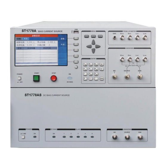
Page 8: Front Panel Description
2.2 Front Panel Description Power Switch Press down to power on, push out to power off. Start Button To start output Stop Button To stop output DC Bias LED... - Page 9 When the instrument starts to output, the output indicator lights up. Number Keys Used to input numbers Output Port Current is output from this port. LED Screen Used to display operation interface Brand and Model The brand and model of the instrument Menu Button For menu manipulation 10) USB Interface...
-
Page 10: Chapter 3 Basic Operation
Chapter 3 Basic Operation 3.1 Instruction of main interface 3.1.1 Current Display The total output current can be set on the setting interface or on the main interface. Using the numeric keypad, you can set the current value. The default unit is A. The seting range of current value is listed below: Slaver Amount Set Lower Limit (A) -
Page 11: Current Climbing Progress Bar
3.1.2 Current Climbing Progress Bar When the instrument starts to output current, there is a climbing process. The higher the current is, the slower the climbing will be. Therefore, in order to visually display the current climbing process, there is a current climbing progress bar. -
Page 12: Parameter Setting
As shown in the figure above, the setting interface includes parameter setting and list setting. 3.2.1 Parameter Setting 3.2.1.1 Current Output Make use of the numeric keyboard to set the total current output value, the default unit is A. The current setting range is listed below: Slaver Amount Set Lower Limit (A) Set Upper Limit (A) -
Page 13: List Setting
3.2.2 List Setting 3.2.2.1 Current Begin Make use of the numeric keyboard to set the current begin value, the default unit is A, the setting range is 0~120A. 3.2.2.2 Current End Make use of the numeric keyboard to set the current end value, the default unit is A, the setting range is 0~120A. 3.2.2.3 Current Step Make use of the numeric keyboard to set the current step value, the default unit is A, the setting range is 0~120A. -
Page 14: System And Tool Settings
According to the three parameters of current begin, current end and scan point to generate the list automatically. If current begin is I , current end is I , scan point is n, then the current step can be represented as I ……, I ) /(n-1). - Page 15 3.3.1.2 Foot Mode There are two foot modes which are listed below: Trig Mode: Step one time to start outputting, step one time again to stop outputing. Hold Mode: Step and hold on the switch to start outputting, loosen the switch to stop outputting. 3.3.1.3 Beep Volume To set the speaker to ON/OFF.
-
Page 16: System Tool
3.3.2 System Tool 3.3.2.1 Software Update Copy the upgrade program file (ST1778A.sec) to the USB root directory Insert the USB disk to the USB interface on the front panel Select Update to upgrade the software, and there will be a progress bar to indicate the progress ... -
Page 17: Instruction Of Instrument Output
3.3.2.5 Password Users are able to set a new password, or change the password. 3.3.2.6 Slave Information You can use this feature to view the slave index and its software version. 3.4 Instruction of Instrument Output 3.4.1 Current Output There are three methods to start outputing current which are listed below: 3.4.1.1 Start Button Press the start button to start outputting current. -
Page 18: Stop Current Output
Single Output: Output a single current value. Steps Output: In accordance with the set list, and output current in order. Chapter 4 Command 4.1 ST1778A RS232 Instruction As the most serial ports, ST1778 is not based on RS-232 strictly, only a min. subset. As figure: Signal Abbr. -
Page 19: Scpi Command
(5) GND As can be seen from the figure above, the serial port connecting line needs to be crossed, so please be aware of it when purchasing it. Users can also buy the serial port cable from Sourcetronic. 4.2 SCPI Command Note that all the following command are sent and received as strings. -
Page 20: State Sub-System Command
Command Format: Set Format: :PARA:CURR <data> Query Format: :PARA:CURR? Data: Data Type: Float, 4 bytes Data Range:0~120 Data Accuracy: 0.1 Data Unit: A Set Example: To set the current to 1A, enter the command: :PARA:CURR 1 Query Example: If you enter the command: :PARA:CURR?, the returned content is:1, indicating the current current is 1A. - Page 21 Returned Info: Data type: Unsigned integer, 1 byte Data Range: 0~31(0x1F) Meaning: Bit0: On or Off Bit1: Running or not Bit2: Over-heat or not Bit3: Overload or not Bit4: Unbalanced or not Query Example: If you enter the command: :STAT:HOST?, the returned content is: 1 has the following meaning: Bit0: 1 The host has been turned on Bit1: 0 Not running...
-
Page 22: System Sub-System Command
Data Range: running, preparing Meaning: Running: The instrument is outputting current Preparing: The instrument is in the state of preparing Query Example: If you enter the command: :STAT:WORK?, the returned content is: running, indicating the instrument is outputting current. 4.2.4 System Sub-System Command System Sub-System Command is used to remotely set the system of the instrument. -
Page 23: Working Sub-System Command
Data Type: Enumeration, 1 byte Data Range:CHI, ENG Data Accuracy: - Data Unit: - Set Example: To set the system language to Chinese, enter the command: :SYST:LANG CHI Query Example: If you enter the command: :SYST:LANG?, the returned content is: CHI, indicating the current system language is Chinese. -
Page 24: Other Command
Function: Set working mode, Sourcetronic mode or Common mode Command Format: :DEVI:MODE <data> Data: Data Type: Enumeration, 1 byte Data Range: COMM, TH Data Accuracy: - Data Unit: - Set Example: To set to Sourcetronic mode, enter the command: :DEVI:MODE TH, the returned content will be 1778. - Page 25 SOURCETRONIC GMBH Fahrenheitstrasse 1 28359 Bremen Germany T +49 421 2 77 99 99 F +49 421 2 77 99 98 info@sourcetronic.com www.sourcetronic.com skype: sourcetronic www.sourcetronic.com...
Need help?
Do you have a question about the ST1778A and is the answer not in the manual?
Questions and answers