
Related Manuals for Sourcetronic ST2690 Series


Summary of Contents for Sourcetronic ST2690 Series
- Page 1 SOURCETRONIC – Quality electronics for service, lab and production User Manual Electrometer / High Resistance Meter ST2690...
-
Page 2: Table Of Contents
ST2690 Electrometer / High Resistance Meter Contents Contents Contents ................................ 1 1 Overview ..............................5 1.1 Sourcetronic ST2690 Series ........................ 5 1.2 Inspecting the Shipment ........................5 1.3 Operating Conditions ........................... 6 1.3.1 Power ............................6 1.3.2 Environmental Conditions ........................ 6 1.3.3 Preheating ............................ - Page 3 ST2690 Electrometer / High Resistance Meter Contents 4.7 Environment System .......................... 31 4.8 BUS System ............................33 4.8.1 RS232 ............................33 4.8.2 LAN ............................... 34 4.8.3 USB............................... 34 4.9 SetSys ............................... 35 4.10 Handler ............................36 4.11 File ..............................37 4.12 Tool ..............................
- Page 4 ST2690 Electrometer / High Resistance Meter Contents 5.10.1 Connection ..........................59 5.10.2 TRIG IN ............................59 5.10.3 TRIG OUT ........................... 60 5.11 Voltage Source Waveform Output..................... 60 5.11.1 Single Staircase Sweep ....................... 60 5.11.2 Double Staircase Sweep ......................61 5.11.3 Square Waveform Output......................61 5.11.4 List Sweep Output........................
- Page 5 ST2690 Electrometer / High Resistance Meter Contents 6.6.7 RES Resistance Meter Command Set ................... 75 6.6.8 CHAR Electrometer Command Set ....................77 6.6.9 SRC Voltage Source Command Set ....................80 6.6.10 FILT Filter Command Set ......................81 6.6.11 MATH Mathematical Command Set ..................... 82 6.6.12 WAVE Waveform Settings Command Set ..................
-
Page 6: Overview
• ST2691A Picoammeter ST2690 series use 5-inch LCD capacitive touch screen with several shortcut buttons. It supports various functions such as limit test, mathematical formula operation and drawing. The SCPI (Standard Commands for Programmable Instruments) command can be used to automate measurements using an external computer. -
Page 7: Operating Conditions
ST2690 Electrometer / High Resistance Meter Overview When you open the boxes that contain the ST2690 series and accessories, check the components against the contents lists attached to the boxes. If anything is found missing, please contact Sourcetronic. Verify the operation of the ST2690 as described in "Checking the Operation of ST2690". If any problem occurs, please contact Sourcetronic. -
Page 8: Checking For Errors
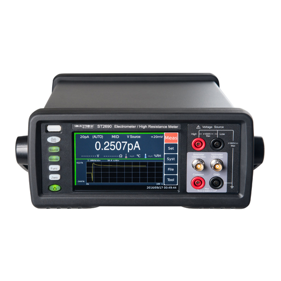
ST2690 Electrometer / High Resistance Meter Overview Press the standby switch to turn on the instrument. The initialization screen will appear on the ST2690’s front panel display and the power-on self-test is automatically executed. If the ST2690 is operating normally, the front panel LCD displays the image as shown below. -
Page 9: Important Notes
Failure to comply with these precautions or with specific warnings elsewhere in this manual may impair the protections provided by the instrument. In addition, it violates safety standards of design, manufacture, and intended use of the instrument. Sourcetronic assumes no liability for customer’s failure to comply with these requirements. -
Page 10: Power Supply And Measurement Safety
Instruments that appear damaged or defective should be made inoperative and secured against unintended operation until they can be repaired by qualified service personnel. Return the instrument to Sourcetronic sales or service office for services and repair to ensure that safety features are maintained. -
Page 11: High Voltage Shock Hazard
Important Notes 2.1.2 High Voltage Shock Hazard Warning! Sourcetronic ST2690/ST2690A can apply dangerous voltages (±1000V) at the High/Low terminal. To prevent electric shock hazard, the following safety precautions must be observed during the use of Sourcetronic ST2690/ST2690A! Use a three-conductor AC power cable to appliance coupler (inlet) and the instrument to anelectric ground (safety ground). -
Page 12: Introduction To Panels
ST2690 Electrometer / High Resistance Meter Introduction to Panels 3 Introduction to Panels The content of this chapter is only a general description; please refer the specific operation and detailed explanations to the corresponding content of Chapter 4. 3.1 Introduction to the Front Panel Figure showing the ST2690 Front Panel: •... - Page 13 ST2690 Electrometer / High Resistance Meter Introduction to Panels • Voltage Source Key (Source), for ST2690/ST2690A Enables or disables Voltage Source Output. In the ON status, the Voltage Source High terminal is connected to the voltage source and the switch light turns green. In the OFF status, it is opened and the switch light turns off. The switch turns red if the voltage source is in the high voltage state (over ±20V).
-
Page 14: Introduction To The Rear Panel
ST2690 Electrometer / High Resistance Meter Introduction to Panels • Common Terminal (Common) It is the Banana terminal for circuit common. This is the Common for the Ammeter, the Voltmeter, and the Analog Out. For the grounded measurement, this terminal must be connected to the earth (ground) terminal by using a Banana-to-Lug cable (furnished). - Page 15 ST2690 Electrometer / High Resistance Meter Introduction to Panels For example, the output voltage is 2 V if the measurement result is the full scale value of the measurement range or 0.2 V if the result is 10 % of the full scale. •...
-
Page 16: Operation Instructions
ST2690 Electrometer / High Resistance Meter Operation Instructions 4 Operation Instructions This chapter describes how to operate the Sourcetronic ST2690 series. 4.1 Home Screen Introduction The figure shows the home screen display. Display Area: Set the measuring range Set the measuring speed Voltage source: The output voltage of the voltage source. -
Page 17: Measurement Settings
ST2690 Electrometer / High Resistance Meter Operation Instructions 4.2 Measurement Settings Under Set – Meas Set interface, settings of the parameters for each function are available. 4.2.1 Ammeter Settings Current Measurement Range (I Range) Optimal range for ammeter measurement values. While the ammeter is running, select I Range and choose the measurement range by touching the check box on the screen. -
Page 18: Voltmeter Settings
ST2690 Electrometer / High Resistance Meter Operation Instructions • 200pA : 20pA~200pA • 20pA: 0~20pA Measurement Speed Choose the speed of measurements. • FAST: 1*PLC (20ms), quick • MID: 10*PLC (200ms) • SLOW: 100*PLC (2000ms), stable Sorting Switch This function can set the sorting mode on or off; sorting results are displayed in the measurement interface. •... -
Page 19: High Resistance Meter
ST2690 Electrometer / High Resistance Meter Operation Instructions Measurement Speed Choose speed of measurements. • FAST: 1*PLC (20ms), quick • MID: 10*PLC (200ms) • SLOW : 100*PLC (2000ms), stable Sorting Switch This function can set the sorting mode on or off; sorting results are displayed in the measurement interface. •... - Page 20 ST2690 Electrometer / High Resistance Meter Operation Instructions Resistance Range (R Range) Optimal range for high resistance meter measurement values. While the high resistance meter is running, select R Range and choose the measurement range by touching the check box on the screen. •...
-
Page 21: Electro Meter Settings
ST2690 Electrometer / High Resistance Meter Operation Instructions 4.2.4 Electro Meter Settings Charge Range Optimal range for electro meter measurement values. While the electro meter is running, select C Range and choose the measurement range by touching the check box on the screen. •... -
Page 22: Voltage Source Settings
ST2690 Electrometer / High Resistance Meter Operation Instructions Lower Set the sorting lower limit Discharge If this function is enabled, the coulomb meter resets the charge when the charge reaches the specified level. • ON: Discharge • OFF: No Discharge Discharge Level This function sets the level of dischage •... -
Page 23: Configuration Settings
ST2690 Electrometer / High Resistance Meter Operation Instructions Off State This function sets the state when voltage source output is off. • High Z : High resistance state, output switch of the ammeter is off, voltage source settings remain unchanged, only used for voltage source measurement range between -20V~20V •... -
Page 24: Math
ST2690 Electrometer / High Resistance Meter Operation Instructions Average This filter calculates a sum of samples in the certain range (number of samples), then divides it by the number of samples. For example: Assuming the number of samples is 5, 5 measurements are A,B,C,D,E, then the filter result is calculated by taking the average: (A+B+C+D+E) /5. -
Page 25: Graph
ST2690 Electrometer / High Resistance Meter Operation Instructions 4.4.1 Graph Wave Form Display (W Disp) This function toggles wave form display on or off. • ON: Display on, shown in the Measurement interface. • OFF: Display off, not shown in the Measurement interface. Wave Form Type (W Type) This function sets the wave form types •... -
Page 26: Histogram
ST2690 Electrometer / High Resistance Meter Operation Instructions • U(V): Measurement Voltage Value • R(Ω): Measurement Resistance Value • Q(C): Measurement Charge Value Xmax, Xmin This function sets the max/min values for the X axis Ymax, Ymin This function sets the max/min values for the Y axis Range Auto (R Auto) This function sets whether the Y axis automatically adjust its range •... - Page 27 ST2690 Electrometer / High Resistance Meter Operation Instructions Limit Test (L Test) This function toggles limit test on or off. • ON: Limit Test function on • OFF: Limit Test function off Limit Mode (L Mode) This function chooses the mode for Limit Test •...
-
Page 28: Source Setting
ST2690 Electrometer / High Resistance Meter Operation Instructions 4.6 Source Setting Set for Voltage Source Waveform Output under Set-SrcSet. 4.6.1 Linear Single (LinearS) Starting Voltage (Start) Set the starting voltage for linear single function Stopping Voltage (Stop) Set the stopping voltage for linear single function Stepping Voltage Set the stepping voltage for linear single function Trigger Mode... -
Page 29: Linear Double (Lineard)
ST2690 Electrometer / High Resistance Meter Operation Instructions 4.6.2 Linear Double (LinearD) Starting Voltage (Start) Set the starting voltage for linear double function Stopping Voltage (Stop) Set the stopping voltage for linear double function Stepping Voltage Set the stepping voltage for linear double function Trigger Mode Set the trigger mode for linear single function •... -
Page 30: Square Waveform Output (Arb Squ)
ST2690 Electrometer / High Resistance Meter Operation Instructions 4.6.3 Square Waveform Output (ARB Squ) Starting Voltage (Start) Set the starting voltage for square waveform function Delay Set how long time the starting voltage lasts for. Peak Set the peak voltage Peak Delay (P Delay) Set how long time the peak voltage lasts for. -
Page 31: List
ST2690 Electrometer / High Resistance Meter Operation Instructions 4.6.4 List Begin Set from which number on the list the function starts with. Set till which number on the list the function ends with. Count Set how many times the list function repeats. Assign Voltage Assign voltage value in the corresponding field. -
Page 32: Environment System
ST2690 Electrometer / High Resistance Meter Operation Instructions 4.7 Environment System Configurations for Environment System is under Syst-EnviSys. Language Set the system language for the instrument. • CHN: Chinese • ENG: English Beep Turn the beeper on or off. • ON: Beeper On •... - Page 33 ST2690 Electrometer / High Resistance Meter Operation Instructions Saved Data example: Date: 2021/11/10 13:56 Time Volt Curr Coul Math Temp 13:57:03.0 3.06E+00 1.99E-05 1.00E+06 0.00E+00 --.-- 2.00E+01 2.43E+01 2.64E-01 13:57:03.3 3.06E+00 1.99E-05 1.00E+06 0.00E+00 --.-- 2.00E+01 2.43E+01 2.64E-01 13:57:03.6 3.06E+00 1.99E-05 1.00E+06 0.00E+00...
-
Page 34: Bus System
ST2690 Electrometer / High Resistance Meter Operation Instructions 4.8 BUS System Configurations for the remote interface of the instrument, under Syst-BusSys. 4.8.1 RS232 Address (Addr) Set the address of the instrument when using the MODBUS protocol. Baud Rate (BaudRt) Set the baud rate. •... -
Page 35: Lan
ST2690 Electrometer / High Resistance Meter Operation Instructions 4.8.2 LAN Port Set the port number for LAN IP Address (IPAddr) Set the IP address for LAN Gateway Set the gateway for LAN Net Mask (Netmsk) Set the subnet mask for LAN 4.8.3 USB v1.0... -
Page 36: Setsys
ST2690 Electrometer / High Resistance Meter Operation Instructions Mode Set the USB mode. • CDC: set the USB mode to CDC • TMC: set the USB mode to TMC Note: After changing the USB mode, the instrument needs to be restarted to be effective for use. 4.9 SetSys Testing Mode (Test) Set the testing mode. -
Page 37: Handler
ST2690 Electrometer / High Resistance Meter Operation Instructions T Dly Set the delay time for the instrument measuring. S Dly Set the delay time for starting the voltage source. Interlock Switch to toggle On/Off Interlock • ON: When the output voltage is greater than 20V, required to short the interlock switch •... -
Page 38: File
ST2690 Electrometer / High Resistance Meter Operation Instructions 4.11 File In the file interface, users can save the loading parameters (.sta) or system parameters (.prf); delete and copy the internal files or USB files of the instrument. 4.12 Tool Reset This function is used to initialize the instrument to factory settings, reset all parameters, and automatically restart the instrument Cali... - Page 39 ST2690 Electrometer / High Resistance Meter Operation Instructions Version Displays information about the instrument version. Error Error message pops up when operation errors or self-test errors occur. Check the errorcode and eliminate the errors by following the prompts. Error Code Code Description Error sending command data CRC check error...
- Page 40 ST2690 Electrometer / High Resistance Meter Operation Instructions V Board HV_V alert, check for potential overloading V Board LV_I alert, check for potential overloading V Board OPA_TEMP alert, check for potential overheating V Board HV_I alert. check for potential overloading Main Board self-check AD error Main Board U606-Pro, check whether the ammeter input is too large Main Board U6-Pro, ammeter error...
-
Page 41: Instrument Measurements And Instructions
ST2690 Electrometer / High Resistance Meter Instrument Measurements and Instructions 5 Instrument Measurements and Instructions 5.1 Current Measurement ST2690/ST2690A/ST2691/ST2691A supports current measurement as shown in table 5-1: Table 5-1 Current Measurement Range, Value, and Resolution Range Value Measurement Value Display Resolution 20mA 0~±21 mA 10 nA... -
Page 42: Procedure
ST2690 Electrometer / High Resistance Meter Instrument Measurements and Instructions Figure 5-2 Current Measurement Connection, Grounded, Typical Figure 5-3 Current Measurement Connection (if DUT has a non-ground potential) Note: For floating the ammeter, do not connect any cable between Common and chassis ground. See "Common Terminal Connection". -
Page 43: Setup Parameters
ST2690 Electrometer / High Resistance Meter Instrument Measurements and Instructions See Figure 5-3 if DUT has a non-ground potential. Press the Ammeter key to enable Ammeter. This turns the switch green. Press the Run/Stop to start the measurement (contineous/single). Press the Ammeter key to disable Ammeter. This turns off the switch light. For more precise measurement, use the zero correction or offset cancel. -
Page 44: Voltage Measurement
ST2690 Electrometer / High Resistance Meter Instrument Measurements and Instructions In the protected case (Figure 5-4 right), Ileak does not flow through the ammeter and does not affect the measurement. If the potential difference between the two ends of the Rguard is 0, no leakage current will flow there. - Page 45 ST2690 Electrometer / High Resistance Meter Instrument Measurements and Instructions Figure 5-5 Simplified Circuit Diagram of Voltmeter Note: Voltmeter connector’s inner shield is internally connected to Guard or Common as shown in Figure 5-5. The internal connection must be made properly. It must be connected to Guard for the guarded voltage measurement. And it must be connected to Common for the unguarded voltage measurement.
-
Page 46: Procedure
ST2690 Electrometer / High Resistance Meter Instrument Measurements and Instructions Figure 5-7 Unguarded Voltage Measurement Connections Instead of connecting the inner shield (Common) of Voltmeter, a banana to alligator clip cable can be used for connecting Common to low terminal of voltage under test. Note: For floating voltmeter, do not connect any cable between Common and chassis ground. -
Page 47: Guarded And Unguarded Connections
ST2690 Electrometer / High Resistance Meter Instrument Measurements and Instructions 5.2.4 Guarded and Unguarded Connections Voltmeter input is a triaxial connector. The center conductor and the outer shield are connected to the voltmeter input and the chassis ground respectively. And the inner shield must be connected to Guard for the guarded voltage measurement or Common for the unguarded voltage measurement. -
Page 48: Resistance Measurement
ST2690 supports the resistance measurement up to 1000 PΩ (reference value); the ST2690A supports the resistance measurement up to 10 PΩ (reference value). ST2690 series supports the resistance measurement capability shown in Table 5-3. Table 5-3 Resistance Range, Value, and Resolution... -
Page 49: Requirements
ST2690 Electrometer / High Resistance Meter Instrument Measurements and Instructions 1GΩ 200nA ≥100MΩ 1kΩ 10GΩ 20nA ≥1GΩ 10kΩ 100GΩ ≥10GΩ 100kΩ 1TΩ ≥100GΩ 1MΩ 10TΩ 200pA 200V ≥1TΩ 10MΩ 100TΩ 20pA ≥10TΩ 100MΩ Manual Auto or locked Manual 5.3.1 Requirements Before turning the instrument on, connect cable, test leads, test fixture, and so on, used for the measurement. -
Page 50: Procedure
ST2690 Electrometer / High Resistance Meter Instrument Measurements and Instructions Note: To apply a voltage over ±21V, the interlock terminal must be connected to an interlock circuit. See "Installing the Interlock Circuit". Note: Voltage Source Low terminal is internally connected to or disconnected from the circuit common as shown in Figure 5-10. -
Page 51: Resistance Calculation Mode
ST2690 Electrometer / High Resistance Meter Instrument Measurements and Instructions Press the Source key to enable the voltage output. This turns the switch green, and the voltage source starts output. Press the Run/Stop key to start a repeat (continuous) measurement. Resistance measurement is performed repeatedly. -
Page 52: Charge Measurement
ST2690 Electrometer / High Resistance Meter Instrument Measurements and Instructions 5.4 Charge Measurement ST2690 supports the charge measurement capability shown in Table 5-4. The coulomb meter uses the ammeter terminal as input terminal. Table 5-4 Charge Measurement Range, Value, and Resolution Range Value Measurement Value Display Resolution... -
Page 53: Procedure
ST2690 Electrometer / High Resistance Meter Instrument Measurements and Instructions 5.4.2 Procedure You can perform the charge measurement as follows. Set the automatic discharge function. Press the Func key to selet the charge measurement mode. Set the charge measurement range on the display screen. Set the desired measurement speed on the display screen. -
Page 54: Voltage Source
ST2690 Electrometer / High Resistance Meter Instrument Measurements and Instructions 5.5 Voltage Source ST2690/ST2690A supports the voltage source measurement capability shown in Table 5-5. Table 5-5 Voltage Output Range, Value, Resolution, and Maximum Current Range Value Measurement Value Display Resolution Maximum Current -20≤V≤20 700 uV... -
Page 55: Temperature And Humidity Measurement
ST2690 Electrometer / High Resistance Meter Instrument Measurements and Instructions 5.6 Temperature and Humidity Measurement ST2690/ST2690A supports temperature and humidity measurement capability. With the factory default setting, the ST2690/ST2690A will measure temperature and humidity if the sensor is connected properly. The instrument will measure and record every other 10s and displays them on the Measurement interface. -
Page 56: Installing The Interlock Circuit
5.7 Installing the Interlock Circuit This section is applied to Sourcetronic ST2690/ST2690A which supports the interlock function. The interlock circuit is a simple electric circuit, as shown in Figure 5-14. The circuit electrically opens when an access door is opened, and closes when the door is closed. -
Page 57: Bin Limit Test
ST2690 Electrometer / High Resistance Meter Instrument Measurements and Instructions Figure 5-14 Interlock Circuit 5.8 BIN Limit Test This instruement supports limit sorting, it peforms a pass/fail judgment for a measurement data or math result data by comparing with predefined test limit (upper and lower limit), then classifies the data using the results. Maximum of seven limit tests can be defined and used for the bins of composite limit test, and the results can be output via Handler. - Page 58 ST2690 Electrometer / High Resistance Meter Instrument Measurements and Instructions Example: • Limit Test: On • Fail Interval: Outside Interval BIN1 upper limit: 150M BIN1 lower limit: -150M BIN2 upper limit: 15M BIN2 lower limit: -15M BIN3 upper limit: 1.5M BIN3 lower limit: -1.5M BIN4 upper limit: 150k BIN4 lower limit: -150k...
-
Page 59: Handler Output
ST2690 Electrometer / High Resistance Meter Instrument Measurements and Instructions Example: • Limit Test: On • Fail Interval: Outside Interval BIN1 upper limit: 1.5k BIN1 lower limit: -1.5k BIN2 upper limit: 15k BIN2 lower limit: -15k BIN3 upper limit: 150k BIN3 lower limit: -150k BIN4 upper limit: 1.5M BIN4 lower limit: -1.5M... -
Page 60: Set Input
ST2690 Electrometer / High Resistance Meter Instrument Measurements and Instructions 5.9.1 Set Input The input can be used to define different functions: start measurement, stop measurement, reset, source off, source on, and source trigger (for voltage source waveform sweep). 5.9.2 Set Output The output function is for the HANDLER limit tests results. -
Page 61: Trig Out
ST2690 Electrometer / High Resistance Meter Instrument Measurements and Instructions 5.10.3 TRIG OUT After receiving TRIG IN signal, TRIG OUT pin will output 20ms low pulse. 5.11 Voltage Source Waveform Output The instrument voltage source can be DC output, single staircase sweep output, double staircase sweep output, square waveform output, list sweep output, in Set-SrcSet. -
Page 62: Double Staircase Sweep
ST2690 Electrometer / High Resistance Meter Instrument Measurements and Instructions 5.11.2 Double Staircase Sweep Set and ouput waveform as shown in the following figure: the output is mirrored by a single staircase sweep into a double staircase sweep. 5.11.3 Square Waveform Output Set and ouput waveform as shown in the following figure: can continuously output square waveform output. -
Page 63: List Sweep Output
ST2690 Electrometer / High Resistance Meter Instrument Measurements and Instructions 5.11.4 List Sweep Output Set and ouput waveform as shown in the following figure: Set any voltage and period time. v1.0... -
Page 64: Offset Cancel And Zero Correction
ST2690 Electrometer / High Resistance Meter Instrument Measurements and Instructions 5.12 Offset Cancel and Zero Correction 5.12.1 Zero Correction The instrument suppors zero correction function, which can clear the deviation of the internal circuit of the instrument. Press the Zero key when electrometer or ammeter is selected to enable zero correction (range locked). The instrument will automatically measure and record all the deviation in current measurement range. -
Page 65: Humidity And Temperature
ST2690 Electrometer / High Resistance Meter Instrument Measurements and Instructions 5.13.3 Humidity and Temperature Water and water vapor can easily cause electrochemical effects. It is effective to maintain constant low humidity in the measurement environment in order to prevent the occurrence of an electrochemical effect. Temperature changes can create contaminating condensation that, in turn, can lead to a serious degradation in the insulation performance. -
Page 66: Capacitive Coupling
ST2690 Electrometer / High Resistance Meter Instrument Measurements and Instructions using the guard technique effective for reducing the electric field change. Current compensation is difficult because the current level changes along with the passage of time. So it is important to wait enough time until the current converges. -
Page 67: Interfaces And Communication
ST2690 Electrometer / High Resistance Meter Interfaces and Communication 6 Interfaces and Communication This instruement supports RS232C serial port, GPIB, LAN, and USB interface for data communication and remote control without instrument panel. They use the same command, but differenct hardwares and protocols. Caution! Electrostatic discharges greater than 1 kV near the interface connectors may cause the unit to reset and require operator intervention. -
Page 68: Communicate With A Computer
IMB AT compatibles. Users can make the three-wire connection cable (length < 1.5m) by using the two-core shielded wire according to the figure, or purchase the serial interface cable between the computer and the instrument from Sourcetronic, or purchase the standard DB9-core cable directly(cross wire). v1.0... -
Page 69: Lan
SCPI instruction of this instrument. 6.2.2 System Configuration Connect the LAN port on the rear panel of the ST2690 series to the network port of the computer through an ethernet cable. Set the IP address and port number. 6.3 USBTMC 6.3.1 USBTMC Remote Control System... -
Page 70: System Configuration
ST2690 Electrometer / High Resistance Meter Interfaces and Communication 6.4.2 System Configuration Connect the USB port on the rear panel of ST2690 to the USB port on the host via a USB cable, set the USB to CDC, see Syst-BusSys-Mode:USB. 6.5 GPIB 6.5.1 GPIB Remote Control System Connect the GPIB card with the ST2690 interface to remotely control the instrument and be compatible with the... -
Page 71: Disp Command Set
ST2690 Electrometer / High Resistance Meter Interfaces and Communication Syntax: *IDN? 6.6.2.2 Instruement Reset Description: Used to reset the instrument, and its parameters. Syntax: *RST 6.6.2.3 Factory Reset Description: Used to factory reset parameters and system settings to the factory defult. Syntax: *FACT 6.6.3 DISP Command Set... -
Page 72: Func Command Set
ST2690 Electrometer / High Resistance Meter Interfaces and Communication 6.6.4 FUNC Command Set 6.6.4.1 Function Selection Description: Used to choose the measurement function of the instrument. Syntax: FUNC? FUNC <RES | VOLT | CURR | COUL | SRC> Parameters: Access the resistance meter VOLT Access the voltmeter CURR... -
Page 73: Volt Voltmeter Command Set
ST2690 Electrometer / High Resistance Meter Interfaces and Communication Syntax: ZERO? ZERO < ON | OFF > Parameters: Turn on Null Turn off Null Example: FUNC:ZERO OFF Turn off Null FUNC:ZERO? Back to the current Null State 6.6.4.5 Run Measurement Description: Used to start the measurement Example: FUNC:RUN... - Page 74 ST2690 Electrometer / High Resistance Meter Interfaces and Communication SLOW Low speed Example: VOLT:SPEED MID Set the voltmeter measurement speed to mid speed. VOLT:SPEED? Back to the current voltmeter measurement speed. 6.6.5.3 Voltmeter Sorting Switch Description: Used to control the voltmeter measurement sorting switch Syntax: SORT? SORT <...
-
Page 75: Curr Ammeter Command Set
ST2690 Electrometer / High Resistance Meter Interfaces and Communication PROT < GUARD | CCOM > Parameters: GUARD GUARD Mode CCOM CCOM Mode Example: VOLT:PROT CCOM Set the Guarded Mode to be CCOM VOLT:PROT? Back to the current voltmeter guarded mode. 6.6.6 CURR Ammeter Command Set 6.6.6.1 Ammeter Measurement Range Description: Used to control the ammeter measurement range... -
Page 76: Res Resistance Meter Command Set
ST2690 Electrometer / High Resistance Meter Interfaces and Communication CURR:SPEED MID Set the ammeter measurement speed to mid speed. CURR:SPEED? Back to the current ammeter measurement speed. 6.6.6.3 Ammeter Sorting Switch Description: Used to control the ammeter measurement sorting switch Syntax: SORT? SORT <... - Page 77 ST2690 Electrometer / High Resistance Meter Interfaces and Communication Parameters: Auto 100TΩ 10TΩ 1TGΩ 100GΩ 10GΩ 1GΩ 100MΩ 10MΩ 1MΩ Manual Example: RES:RANGE 11 Set the resistance meter measurement range to manual. RES:RANGE? Back to the current resistance meter measurement range. 6.6.7.2 Resistance Meter Measurement Speed Description: Used to control the measurement speed of the resistance meter.
-
Page 78: Char Electrometer Command Set
ST2690 Electrometer / High Resistance Meter Interfaces and Communication 6.6.7.4 Resistance Meter Sorting Upper Limit Description: Used to set the resistance meter measurement sorting upper limit. Syntax: UPPER? UPPER < float > Parameters: Float Float data type Example: RES:UPPER 1e7 Set the resistance meter upper limit to 10MΩ... - Page 79 ST2690 Electrometer / High Resistance Meter Interfaces and Communication Parameters: 2~20nC 200~2000nC 20nC 200nC 2000nC Example: CHAR:RANGE 2 Set the electrometer measurement range to 200~2000nC CHAR:RANGE? Back to the current electrometer measurement range 6.6.8.2 Electrometer Measurement Speed Description: Used to control the measurement speed of the electrometer Syntax: SPEED? SPEED <...
- Page 80 ST2690 Electrometer / High Resistance Meter Interfaces and Communication Example: CHAR:UPPER 1e-7 Set the resistance upper limit to 100nC CHAR:UPPER? Back to the current resistance sorting upper limit 6.6.8.5 Electrometer Sorting Lower Limit Description: Used to set the electrometer sorting lower limit Syntax: LOWER? LOWER <...
-
Page 81: Src Voltage Source Command Set
ST2690 Electrometer / High Resistance Meter Interfaces and Communication 6.6.9 SRC Voltage Source Command Set 6.6.9.1 Voltage Source Measurement Range Description: Used to control the voltage source measurement range Syntax: RANGE? RANGE < 1 | 2 | 3 > Parameters: -20~20V 0~1000V -1000~0V... -
Page 82: Filt Filter Command Set
ST2690 Electrometer / High Resistance Meter Interfaces and Communication Parameters: CCOM Common ground FLOAT Floating Example: SRC: GND FLOAT Set the grounding mode to floating SRC: GND? Back to the current grounding mode 6.6.9.5 Power Supply Current Limiting Resistance Description: Used to choose the power supply current limiting resistance Syntax: RES? RES <... -
Page 83: Math Mathematical Command Set
ST2690 Electrometer / High Resistance Meter Interfaces and Communication 6.6.10.2 Filter Sample Number Description: Used to set the voltage source output value Syntax: NUMB? NUMB < int > Parameters: Integer data type Example: FILT:NUMB 3 Set the current filter sample number to 3 FILT:NUMB? Back to the current sample number 6.6.11 MATH Mathematical Command Set... -
Page 84: Wave Waveform Settings Command Set
ST2690 Electrometer / High Resistance Meter Interfaces and Communication Example: MATH:FACT1 1.23 Set the current coefficient 1 to 1.23 MATH:FACT1? Back to the current coefficient 1 6.6.11.3 Function Coefficient 2 Description: Used to set coefficient 2 for the current mathematical function coefficient 2 Syntax: FACT2? FACT2<... - Page 85 ST2690 Electrometer / High Resistance Meter Interfaces and Communication Syntax: TYPE? TYPE < GRAPH | HIST > Parameters: GRAPH Line graph HIST Histogram Example: WAVE: TYPE GRAPH Set the waveform to line graph WAVE: TYPE? Back to the current waveform type 6.6.12.3 Line Graph X-axis Parameter Description: Used to set the parameter of the line graph x-axis Syntax:...
- Page 86 ST2690 Electrometer / High Resistance Meter Interfaces and Communication Parameters: Float Float data type Example: WAVE: GRAPH:XMIN 0.002 Set the x-axis minimum to 0.002 WAVE: GRAPH:XMIN? Back to the current x-axis minimum 6.6.12.6 Line Graph Y-axis Parameter Description: Used to set the parameter of the line graph y-axis Syntax: GRAPH:YPARA? GRAPH:YPARA <...
-
Page 87: Bin Limit Settings Command Set
ST2690 Electrometer / High Resistance Meter Interfaces and Communication 6.6.12.9 Line Graph Auto Ratio Description: Used to set whether to enable auto ratio or not Syntax: GRAPH:AUTOR? GRAPH:AUTOR < ON | OFF > Parameters: Example: WAVE: GRAPH:AUTOR ON Turn on auto ratio WAVE: GRAPH:AUTOR? Back to the current auto ratio state 6.6.12.10 Histogram X-axix Parameter... - Page 88 ST2690 Electrometer / High Resistance Meter Interfaces and Communication Syntax: LMODE? LMODE < GRADING | SORTING > Parameters: GRADING Set to grading mode SORTING Set to sorting mode Example: BIN: LMODE GRADING Set the limit mode to GRADING BIN: LMODE? Back to the current limit mode 6.6.13.3 Feed Data Type Description: Used to set the limit test feed data type...
- Page 89 ST2690 Electrometer / High Resistance Meter Interfaces and Communication Syntax: BTEST? BTEST < 1 | 2 | 3 | 4 | 5 | 6 | 7 > < ON | OFF > Parameters: Index 1 Index 2 Index 3 Index 4 Index 5 Index 6 Index 7...
- Page 90 ST2690 Electrometer / High Resistance Meter Interfaces and Communication Parameters: Index number (1~7) Output (1~14) Example: BIN: PASSPT 1,2 Set the pass pattern output for index 1 to 2 (0010) BIN: PASSPT? Back to the current index pass pattern 6.6.13.8 Fail Pattern Description: Used to set the fail pattern output Syntax: FAILPT?
-
Page 91: Vsfunc Waveform Output Command Set
ST2690 Electrometer / High Resistance Meter Interfaces and Communication 6.6.13.11 BIN Settings Description: Used to configure all settings for one BIN Syntax: SETBIN < n > <m ><a><b ><c ><d ><e > Parameters: Index number (1~7) BIN switch (ON | OFF) Fail on (IN | OUT) Pass pattern (1~14) Fail pattern (1~14) - Page 92 ST2690 Electrometer / High Resistance Meter Interfaces and Communication 6.6.14.2 Single Staircase Sweep Starting Voltage Description: Used to set the single staircase sweep starting voltage Syntax: SSTART? SSTART < float > Parameters: Float Float data type Example: VSFUNC:SSTART 1.2 Set the single staircase sweep starting voltage to 1.2V VSFUNC:SSTART? Back to the starting voltage 6.6.14.3 Single Staircase Sweep Stopping Voltage...
- Page 93 ST2690 Electrometer / High Resistance Meter Interfaces and Communication Example: VSFUNC:STRIG TIMER Set the single staircase sweep trigger mode to timer VSFUNC:STRIG? Back to the trigger mode 6.6.14.6 Single Staircase Sweep Timer Description: Used to set the single staircase sweep timer Syntax: STIMER? STIMER <...
- Page 94 ST2690 Electrometer / High Resistance Meter Interfaces and Communication Parameters: Float Float data type Example: VSFUNC:DSTEP 0.2 Set the double staircase sweep stepping voltage to 0.2V VSFUNC:DSTEP? Back to the stepping voltage 6.6.14.10 Double Staircase Sweep Trigger Mode Description: Used to set the double staircase sweep trigger mode Syntax: DTRIG? DTRIG <...
- Page 95 ST2690 Electrometer / High Resistance Meter Interfaces and Communication Syntax: ADELAY? ADELAY < float > Parameters: Float Float data type Example: VSFUNC:ADELAY 1.2 Set the square wave starting delay to 1.2s VSFUNC:ADELAY? Back to the starting delay 6.6.14.14 Sqaure Wave Peak Voltage Description: Used to set the square wave peak voltage Syntax: APEAK?
- Page 96 ST2690 Electrometer / High Resistance Meter Interfaces and Communication 6.6.14.17 Square Wave Loop Count Description: Used to set the square wave loop count Syntax: ACOUNT? ACOUNT < int > Parameters: Integer data type Example: VSFUNC:ACOUNT 5 Set the square wave loop count to 5 times VSFUNC:ACOUNT? Back to the loop count 6.6.14.18 List Sweep Start Number...
-
Page 97: Sys System Command Set
ST2690 Electrometer / High Resistance Meter Interfaces and Communication 6.6.14.21 List Sweep Settings Description: Used to set the voltage and time for one step Syntax: LSET < int >< m >< n > Parameters: List step number (integer 1~100) Voltage (float data type) Time (float data type) Example: VSFUNC: LSET 10,1.2,2.2... - Page 98 ST2690 Electrometer / High Resistance Meter Interfaces and Communication Example: SYS:ENVI:BEEP ON Turn on system beeper sound SYS:ENVI:BEEP? Back to the beeper switch state 6.6.15.3 Temperature Display Description: Used to set the temperature display mode Syntax: ENVI:TMODE? ENVI:TMODE< CE | FA > Parameters: Degrees Celsius Degrees Fahrenheit...
- Page 99 ST2690 Electrometer / High Resistance Meter Interfaces and Communication 6.6.15.6 Trigger Delay Description: Used to set the trigger delay Syntax: TRIG:DELAY? TRIG:DELAY < float > Parameters: Float Float data type Example: SYS:TRIG:DELAY 0.2 Set the trigger delay time to 0.2s SYS:TRIG:DELAY? Back to the trigger delay time 6.6.15.7 Trigger Space...
- Page 100 ST2690 Electrometer / High Resistance Meter Interfaces and Communication Example: SYS: RANGE:SPEED STAND Set the range switching speed to standard SYS: RANGE:SPEED? Back to the range switching speed 6.6.15.10 Analog Output Description: Used to set the parameters for analog output Syntax: ANALOG? ANALOG <...
-
Page 101: Handler Settings Command Set
ST2690 Electrometer / High Resistance Meter Interfaces and Communication Syntax: DISP? DISP < 3 | 4 | 5 | 6 > Parameters: Display in 3½ bit Display in 4½ bit Display in 5½ bit Display in 6½ bit Example: SYS: DISP 6 Display results in 6½... - Page 102 ST2690 Electrometer / High Resistance Meter Interfaces and Communication 6.6.16.2 PIN2 Settings Description: Used to define the HANDLER-PIN2 input Syntax: PIN2:SIG? PIN2:SIG < START | STOP | RESET | SRCON | SRCOFF | SRCTRG > Parameters: START Start measurement STOP Stop measurement RESET Instrument reset...
-
Page 103: Fetch Inquiry Command Set
ST2690 Electrometer / High Resistance Meter Interfaces and Communication Example: HAND: PIN4:LEV LEVEL Define the PIN4~7 inputs as level input HAND: PIN4:LEV? Back to the PIN4~7 input definition 6.6.17 FETCH Inquiry Command Set 6.6.17.1 Voltage Inquiry Description: Used to check the current voltage measurement value Syntax: FETCH:VOLT? 6.6.17.2 Current Inquiry... - Page 104 ST2690 Electrometer / High Resistance Meter Interfaces and Communication 6.6.17.10 All Values Inquiry Description: Used to check all the above measurement values Syntax: FETCH:ALL? Example (ST2690): Values are: Voltage Current Charge Resistance Time & date Voltage source MATH Temperature Humidity Example (ST2690A): Values are: Voltage...
-
Page 105: Modbus Commands
ST2690 Electrometer / High Resistance Meter Interfaces and Communication Voltage source MATH Temperature Humidity Error code Example (ST2690A): Values are: Voltage Current Charge Time & date Voltage source MATH Temperature Humidity Error code Example (ST2691&ST2691A): Values are: Current Time & date MATH Error code 6.6.17.12 Clear Error Code... -
Page 106: Read Commands
ST2690 Electrometer / High Resistance Meter Interfaces and Communication 6.7.2 Read Commands Send Format: Instrument Function Code Address High Address Low Register High Register Low CRC Low CRC High Address Return Format: Instrument Address Function Code Bit Length Data Bit 1 …... -
Page 107: Func Command Set
ST2690 Electrometer / High Resistance Meter Interfaces and Communication 6.7.4 FUNC Command Set Parameter Parameter Name Write Data Status Address Set the instrument function to resistance meter 1 (U16) Write Set the instrument function to voltmeter 2 (U16) Write Set the instrument function to ammeter 3 (U16) Write 0x1000... -
Page 108: Curr Command Set
ST2690 Electrometer / High Resistance Meter Interfaces and Communication Turn on voltmeter sorting 2 (U16) Write Inquire voltmeter sorting – Read Set the voltmeter sorting upper limit Float Write 0x2003 Inquire the voltmeter sorting upper limit – Read Set the voltmeter sorting lower limit Float Write 0x2004... -
Page 109: Res Command Set
ST2690 Electrometer / High Resistance Meter Interfaces and Communication Inquire the ammeter sorting upper limit – Read Set the ammeter sorting lower limit Float Write 0x3004 Inquire the ammeter sorting lower limit – Read 6.7.7 RES Command Set Parameter Parameter Name Write Data Status Address... -
Page 110: Char Command Set
ST2690 Electrometer / High Resistance Meter Interfaces and Communication 6.7.8 CHAR Command Set Parameter Parameter Name Write Data Status Address Set the electromester measurement range to 2~20nC 1 (U16) Write Set the electromester measurement range to 0.2~2uC 2 (U16) Write Set the electromester measurement range to 2nC 3 (U16) Write... -
Page 111: Src Command Set
ST2690 Electrometer / High Resistance Meter Interfaces and Communication 6.7.9 SRC Command Set Parameter Parameter Name Write Data Status Address Set the voltage source output value Float Write 0x6000 Inquire the voltage source output value – Read Set the output status to HIGHZ 1 (U16) Write Set the output status to NORMAL... -
Page 112: Math Command Set
ST2690 Electrometer / High Resistance Meter Interfaces and Communication 6.7.11 MATH Command Set Parameter Parameter Name Write Data Status Address Set the MATH function off 1 (U16) Write Set the MATH function to scaling migration 2 (U16) Write Set the MATH function to reciprocal scaling migration 3 (U16) Write Set the MATH function to ratio... -
Page 113: Bin Command Set
ST2690 Electrometer / High Resistance Meter Interfaces and Communication Set the line graph X-axis parameter to resistance 5 (U16) Write Set the line graph X-axis parameter to voltage source 6 (U16) Write Set the line graph X-axis parameter to charge 7 (U16) Write Inquire the X-axis parameter... -
Page 114: Vsfunc Command Set
ST2690 Electrometer / High Resistance Meter Interfaces and Communication Inquire limit test – Read Set the limit mode to GRADING 1 (U16) Write 0xE001 Set the limit mode to SORTING 2 (U16) Write Inquire the limit mode – Read Set the limit parameter to current 1 (U16) Write Set the limit parameter to voltage... - Page 115 ST2690 Electrometer / High Resistance Meter Interfaces and Communication Set the waveform output to list sweep 5 (U16) Write Inquire the waveform output type – Read Set the single staircase sweep starting voltage Float Write 0xF001 Inquire the single staircase sweep starting voltage –...
-
Page 116: Sys Command Set
ST2690 Electrometer / High Resistance Meter Interfaces and Communication Set the square wave ending time Float Write 0xF00F Inquire the square wave ending time – Read Set the square wave loop count (U16) Write 0xF010 Inquire the square wave loop count –... -
Page 117: Handler Command Set
ST2690 Electrometer / High Resistance Meter Interfaces and Communication Inquire the trigger delay – Read Set the trigger period Float Write 0xA005 Inquire the trigger period – Read Set the voltage source delay Float Write 0xA006 Inquire the voltage source delay –... -
Page 118: Fetch Command Set
ST2690 Electrometer / High Resistance Meter Interfaces and Communication Set PIN1 to stop voltage source 5 (U16) Write Set PIN1 to trigger source 6 (U16) Write Inqure the PIN1 input signal – Read Set PIN2 to start measurement 1 (U16) Write Set PIN2 to stop measurement 2 (U16) -
Page 119: Technical Parameter Specifications
ST2690 Electrometer / High Resistance Meter Technical Parameter Specifications 7 Technical Parameter Specifications 7.1 Main Technical Specifications Femtometer/Electrometer/ Picoammeter/Insulation Femtometer Picoammeter Resistance Meter Resistance Meter Model ST2690 ST2690A ST2691 ST2691A Measurement 6½ bit 6½ bit 6½ bit 6½ bit Resolution Current 0.1 fA –... -
Page 120: Detailed Technical Specifications
ST2690 Electrometer / High Resistance Meter Technical Parameter Specifications 7.2 Detailed Technical Specifications Conditions: • Temperature: 23°C±5°C • Humidity: 30%~80%RH After 1 hour of pre-heating: • Ambient temperature veriation: less than ±3°C after self-calibration • Calibration Cycle: 1 year 7.2.1 Current Measurement Accuracy: Measurement Range Display Resolution Accuracy±... -
Page 121: Voltage Measurement Accuracy
ST2690 Electrometer / High Resistance Meter Technical Parameter Specifications Note: • These specifications are only for auto measurement range mode. • ST2690A does not support 10TΩ and 100TΩ, ST2691 and ST2691A does not support resistance measurement function. 7.2.3 Voltage Measurement Accuracy: Measurement Range Display Resolution Accuracy±...
Need help?
Do you have a question about the ST2690 Series and is the answer not in the manual?
Questions and answers