Table of Contents
Advertisement
Quick Links
O
P
E
R
A
O
P
E
R
A
TH2516 Series DC Resistance Meter
C C
h h
a a
n n
g g
z z
h h
o o
u u
T T
o o
C
h
a
n
g
z
h
o
u
T
o
A A
d d
d d
: : No.3, Tianshan Road, New District, Changzhou, Jiangsu
A
d
d
:
( (
T T
e e
l l
: :
(
0 0
5 5
1 1
T
e
l
:
0
5
1
( (
F F
a a
x x
: :
0 0
5 5
(
F
a
x
:
0
5
E E
- -
m m
a a
i i
l l
: :
E
-
m
a
i
l
W W
e e
b b
s s
i i
t t
e e
: :
h h
W
e
b
s
i
t
e
:
h
T
I
O
N
M
A
N
T
I
O
N
M
A
N
n n
g g
h h
u u
i i
E E
l l
e e
c c
t t
r r
o o
n n
i i
c c
n
g
h
u
i
E
l
e
c
t
r
o
n
i
) )
, ,
9 9
)
8 8
5 5
1 1
3 3
2 2
2 2
2 2
2 2
,
8 8
5 5
1 1
1 1
3 3
9
8
5
1
3
2
2
2
2
8
5
1
1
3
) )
1 1
9 9
8 8
5 5
1 1
0 0
9 9
9 9
7 7
2 2
)
1
9
8
5
1
0
9
9
7
2
S S
a a
l l
e e
s s
@ @
t t
o o
n n
g g
h h
u u
i i
. .
c c
o o
m m
. .
c c
:
S
a
l
e
s
@
t
o
n
g
h
u
i
.
c
o
m
.
c
t t
t t
p p
: :
/ /
/ /
w w
w w
w w
. .
t t
o o
n n
g g
h h
u u
i i
. .
c c
o o
m m
t
t
p
:
/
/
w
w
w
.
t
o
n
g
h
u
i
.
c
o
U
A
L
U
A
L
C C
o o
. .
, ,
L L
t t
d d
. .
c
C
o
.
,
L
t
d
.
3 3
4 4
2 2
3
4
2
n n
n
. .
c c
n n
m
.
c
n
Advertisement
Table of Contents

Related Manuals for Sourcetronic TH2516 Series


Summary of Contents for Sourcetronic TH2516 Series
- Page 1 TH2516 Series DC Resistance Meter : : No.3, Tianshan Road, New District, Changzhou, Jiangsu ( ( ) ) , , ( ) , ( ( ) ) ( )...
-
Page 2: Table Of Contents
TH2516 Series Operation Manual Contents Introduction to Instrument, Unpacking and Installing ............1 Introduction to Instrument................. 1 Unpacking ......................1 Power Connection ....................1 Fuse ........................2 Environment ....................... 2 Use of Test Fixture ....................2 Warm-up ......................2 Other Features ....................3 Introduction to Front and Rear Panels ................4... - Page 3 TH2516 Series Operation Manual 3.2.4 Compare Mode and SETTINGS of ABS & Percent Error ........13 <BIN DISP> ......................14 STATIS DISP ....................... 15 3.4.1 Edge Mode and Settings of Its Relevant Values ..........15 3.4.2 Status ON/OFF ....................16 3.4.3...
- Page 4 TH2516 Series Operation Manual 4.2.2 Structure of File Folder/File in a U Disk ............28 Performance Index ......................32 5.1.1 Measurement Function ..................32 Measurement Parameters and Notations ............32 5.1.2 Measurement Groups..................32 5.1.3 Range ........................ 32 5.1.4 Trigger ....................... 32 5.1.5...
- Page 5 TH2516 Series Operation Manual 7.1.1 DISPlay Subsystem Commands ................. 41 7.1.2 FUNCtion Subsystem Commands ..............42 7.1.3 APERture Subsystem Commands ..............46 7.1.4 TRIGger Subsystem Commands ................ 46 7.1.5 FETCH? Subsystem Commands ................ 48 7.1.6 TEMPerature Subsystem Commands (TH2516) ..........49 7.1.7...
- Page 6 TH2516 Series Operation Manual Declaration The descriptions contained in this manual may not cover all information about this instrument. Introductions to the improvements of the instrument in performance, function, internal structure, outer appearance, accessories, packing material, etc. are subject to change without notice. If you find any inconformity of this manual with our instruments, please contact us for further consultation by the address listed on the cover.
-
Page 7: Introduction To Instrument, Unpacking And Installing
TH2516 series is a powerful test tool for all kinds of resistor design, detection, quality control and production. Automation on production lines can be greatly improved by the realization of ultra-high test speed and the signal output of 3 compare results through HANDLER interface. -
Page 8: Fuse
TH2516 Series Operation Manual should correspond to the power plug of the instrument. The instrument has been specially designed for decreasing noise jamming caused by the input in AC power terminal, but it is also recommended to use it in the environment of low noise. -
Page 9: Other Features
TH2516 Series Operation Manual Do not turn on or off the instrument frequently. This may cause internal data confusion. 1.8 Other Features Consumption: ≤30VA Dimensions (W*H*D): 235mm*105mm*360mm; this dimension is the final packaging size. Weight: Approx. 3.6kg... -
Page 10: Introduction To Front And Rear Panels
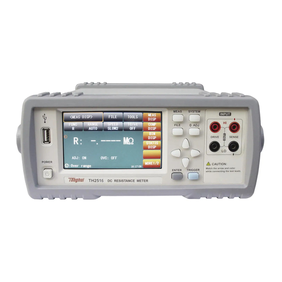
TH2516 Series Operation Manual 2) Introduction to Front and Rear Panels This chapter will describe the basic operation of TH2516. Before using the instrument, please read this chapter carefully. 2.1 Introduction to Front Panel Figure 2-1 shows the front panel of TH2516. -
Page 11: Introduction To Rear Panel
TH2516 Series Operation Manual avoid abnormal measurement. [TRIGGER] When the trigger mode is set as MANU (manual), pressing this key can trigger the instrument manually. [ENTER] Press this key to terminate and store input data. 10) Universal Arrow Keys There are four arrow keys: up, down, left and right arrow keys. -
Page 12: Display Zone
PC can remotely control TH2516 series through USB DEVICE. 2.3 Display Zone TH2516 series adopts 24-bit 4.3-inch LCD touch screen with a resolution of 480*272. The display screen is divided into the following zones, as shown in figure 2-3. Figure 2-3 Display zone Page name This zone shows the current page name. -
Page 13: Introduction To Buttons On Front Panel
TH2516 Series Operation Manual This zone is used to change the measurement mode and measurement parameters. 2.4 Introduction to Buttons on Front Panel 2.4.1 [MEAS] Press <MEAS> to enter into display homepage. Selectable functions in this page are shown as follows: <MEAS DISP>... -
Page 14: Simple Operation
TH2516 Series Operation Manual 2.5 Simple Operation Simple operation steps for TH2516: Use [MEAS], [SYSTEM] or [FILE] or soft keys to enter into the page required to enter. (Refer to figure 3-1) Use arrow buttons ([←] [↑] [→] [↓]) to move the cursor to desired zone. -
Page 15: Basic Operation
TH2516 Series Operation Manual 3) Basic Operation 3.1 <MEAS DISP> Touch the screen or press down [MEAS], the <MEAS DISP> page will be displayed in the screen shown as figure 3-1. Figure 3-1 Measure Display The following measurement parameters can be set on this page. -
Page 16: Measurement Range
TH2516 Series Operation Manual R-T (Resistance and temperature) T (Temperature) LPR (resistance test at low current mode) LPR-T (Temperature and resistance test at low current mode) ---------------------------------------------------------------------------------------------------------------------- Note: Settings and modifications of all functions can be taken by the following steps: 1. -
Page 17: File Manage
TH2516 Series Operation Manual The measurement result of the speed is shown as a 4-digit number with one digit after the decimal point. Touch the speed zone, the following soft keys will be displayed. FAST SLOW1 SLOW2 ... -
Page 18: Comp Disp
TH2516 Series Operation Manual 3.2 <COMP DISP> Touch <MEAS DISP> or press [MEAS] to select the COMP DISP soft key to enter into the <COMP DISP> page shown as figure 3-2. MEAS <COMP DISP> FILE TOOLS DISP COMP COMP COMP MODE HIGH 225.000... -
Page 19: Tools
TH2516 Series Operation Manual this function will be disabled. Save Data OFF: Touch this key, this key will turn to <Save Data ON> and each measurement result will be continuously saved to the .CSV file in U disk. Before a U disk is inserted, the save function will be disabled. -
Page 20: Bin Disp
TH2516 Series Operation Manual value is the base value in bias display mode. 3.3 <BIN DISP> Touch <MEAS DISP> or press [MEAS]. Then select the soft key BIN DISP to enter into <BIN DISP> shown as figure 3-3. MEAS <BIN DISP>... -
Page 21: Statis Disp
TH2516 Series Operation Manual setting, the corresponding bin will be displayed in grey; RED: When the corresponding bin comparator result is different from the bin setting, the corresponding bin will be displayed in red; GREEN: When the corresponding bin comparator result is different from the bin setting, the corresponding bin will be displayed in green. -
Page 22: Status On/Off
TH2516 Series Operation Manual When ABS is selected, the adjacent two items on the same line will be high and low limits. Touch them to set the values. When % is selected, the two items on the same line will be nominal value and percent. -
Page 23: Tools
TH2516 Series Operation Manual Hi (num): Be used to add up times that the measurement result exceeds the upper limit value. Lo (num): Be used to add up times that the measurement result is less than the lower limit value. -
Page 24: Meas Setup
TH2516 Series Operation Manual VCOUNT Valid count times STAT System status Time Test time NOTE 2: Before switching from statistics interface to other interface, please firstly set the statistics status as OFF. 3.5 <MEAS SETUP> Touch the main menu. And then touch the soft key MEAS SETUP to enter into the MEAS SETUP page shown as figure 3-5. -
Page 25: Tc/∆T Setup> (Th2516)
TH2516 Series Operation Manual 0 ADJ: Touch this key to select ON or OFF. ON is to turn on the short correction function while OFF is to turn off. OVC: Touch this key to select ON or OFF. ON is to turn on the compensation voltage while ... -
Page 26: Temperature Conversion (∆T)
TH2516 Series Operation Manual NOTE: Before measurement, it is necessary to warm up the instrument and the probe for about half an hour. The temperature sensor should be placed to the DUT as close as possible but cannot contact it. After the displayed result comes to be stable, you can read or record the result. -
Page 27: Types Of Temperature Sensor
TH2516 Series Operation Manual Chromium copper Chromium: 0.4 to 8.89 0.40 to 0.50 0.80 to 0.85 Anti-corrosion alloy Nickel: 2.5 to 4.0 0.25 to 0.45 980 to 1770 Silicon: 0.5 to 1.0 Soft aluminum Aluminum>99.5 0.63 to 0.64 Hard-drawn Aluminum>99.5 0.60 to 0.62... -
Page 28: Parameter Setting
TH2516 Series Operation Manual − − InputVoltage − − ----------------------------------------------------------------------------------------------------------------------------- NOTE: V1 and V2 range from 00.00V to 02.00V while T1 and T2 range from -99.9℃ to 999.9℃. Parameter Setting 3.6.4 t0: Touch this key, the numeric keyboard will pop up and you can input the reference ... -
Page 29: Bin Setup
TH2516 Series Operation Manual 3.7 <BIN SETUP> Touch the main menu. And then touch MORE 1/2 to select BIN SETUP, and the corresponding Bin Setup page will be displayed as figure 3-7: Figure 3-7 Bin Setup On this page you can set all parameters concerned with the bin comparator. There are 3 groups of parameters (high and low limits, nominal value, %) can be set. -
Page 30: System Setup And File Manage
TH2516 Series Operation Manual 4) System Setup and File Manage 4.1 System Setup Entering the system setup page, you can press [SYSTEM] or touch MORE2/2 on any display page to select system setup function as shown in figure 4-1. MEAS <SYSTEM SETUP>... -
Page 31: Touchtone
TH2516 Series Operation Manual TouchTone 4.1.2 The function is used to control the touch tone. Steps for setting the touch tone Touch TouchTone, the following soft keys will be displayed: Touch this key to turn on the touch tone. -
Page 32: Bus Mode
TH2516 Series Operation Manual again and press [ENTER] to confirm. Then the numeric keyboard will be displayed for the third time, please input the new password. Press [ENTER] to finish the password modification. NOTE: The default password is 2516. Bus Mode 4.1.5... -
Page 33: Lcd Style
Touch this key, the cursor under the time will move right. 4.2 <File Manage> TH2516 series can save parameters that are set by user to the internal non-volatile memory in the file format. User can load the file to use these parameters instead of resetting. -
Page 34: Structure Of File Folder/File In A U Disk
TH2516 Series Operation Manual Flash or external U disk. Introduction to Methods and Applications of Save The table below shows the applicable save methods and applications: save method recall application type file format configuration save *.STA Save the current configuration to (internal Flash) internal Flash. - Page 35 TH2516 Series Operation Manual E:(U disk) \STA 2516001.STA 2516002.STA 2516003.STA 2516999.STA \CSV 2516001.CSV 2516002.CSV 2516003.CSV 2516999.CSV \IMAGE 2516001.GIF 2516002.GIF 2516003.GIF 2516999.GIF …… Figure 4-2 file structure in a U disk When using a U disk on TH2516, you should pay special attention to the following points: 1.
- Page 36 TH2516 Series Operation Manual Figure 4-3 External file page Figure 4-4 External file page Four files’ information will be displayed in the internal file page or the external file page, including file names and time of being saved. Operations of the internal file and the external file are similar. Take internal file operations as an example to describe the specific procedures of file operations.
- Page 37 TH2516 Series Operation Manual be displayed in the soft key zone. When [YES] is selected, the instrument will load the setup data in the file; when [NO] is selected, the current operation will be cancelled. Save Touch this key, [YES] and [NO] will be displayed in the soft key zone. When [NO] is selected, the current operation of save file will be cancelled;...
-
Page 38: Performance Index
TH2516 Series Operation Manual 5) Performance Index 5.1 Measurement Function Measurement Parameters and Notations 5.1.1 R:Resistance T: Temperature LPR: Low current mode Measurement Groups 5.1.2 Five measurement groups are available: TH2516: R, R-T, T, LPR, LPR-T TH2516A, TH2516B: R, LPR Range 5.1.3... -
Page 39: Resistance Measurement Time
TH2516 Series Operation Manual Resistance Measurement Time 5.1.6 When OVC is OFF, measurement time= 5ms +t1 (50 Hz) / 5ms+t1 (60 Hz) FAST 20ms+t1 (50 Hz) / 16.6ms+t1 (60 Hz) 110ms+t1 (50 Hz) / 110ms+t1 (60 Hz) SLOW 450ms +t1 (50 Hz) / 450ms+t1... -
Page 40: Measurement Accuracy
TH2516 Series Operation Manual 5.3 Measurement Accuracy Measurement accuracy includes the basic measurement accuracy under environmental conditions of basic temperature and humidity and temperature correction factor beyond the environmental conditions of basic temperature and humidity. Checking the measurement accuracy should be taken under the following circumstances: a.... -
Page 41: Accuracy For Resistance Tested At Low Current Mode
TH2516 Series Operation Manual Basic Measurement Accuracy in one year of TH2516A (23±5℃, ≤80%RH) Range 200mΩ 2Ω 20Ω 200Ω 2kΩ 20kΩ 200kΩ Current 100mA 10mA 100µA 100µA 10µA 0.7V Resolution 10µΩ 100µΩ 1mΩ 10mΩ 100mΩ 1Ω 10Ω Accuracy 0.05%+2 Temperature... -
Page 42: Accuracy For Temperature Measurement (Analog Input)
TH2516 Series Operation Manual Accuracy for Temperature Measurement (Analog Input) 5.3.4 TH2516 Basic Measurement Accuracy in one year (23±5℃, ≤80%RH) Input voltage range 0 to 2V Temperature range display -99.9℃ to 999.9℃ Resolution Accuracy ±1%Rd ± 3mV Accuracy= 1%* ( –... -
Page 43: Remote Control
TH2516 Series Operation Manual 6) Remote Control 6.1 RS232C Connection RS-232 standard, also called as asynchronous serial communication standard, has already been widely used for data communication between computers, computer and external equipment. RS is the English abbreviation of Recommended Standard; 232, the standard number. This standard is issued by EIA in 1969, which rules to send one bit in a data line every time. -
Page 44: Usbtmc Remote Control System
TH2516 Series Operation Manual transmitted to the instrument, it is required to send LF (hexadecimal: 0AH) as the terminating character. Each time the maximum receivable number of SPCI command string is 2kB. For result data formats transmitted to a PC from the instrument, see Commands Reference. -
Page 45: Usbvcom Virtual Serial Port
TH2516 Series Operation Manual Figure 6-11 Procedure 2 of Installing USB Driver When the installation of driver is finished, user can see “usb test and measurement device” in the device manager of PC, as is shown in the following figure. -
Page 46: System Configuration
TH2516 Series Operation Manual System Configuration 6.3.1 Connect PC and TH2516 to the USB interface through a USB cable. Installing Driver 6.3.2 Methods of installing USBVCOM driver are the same with that of installing USBTMC driver. When the installation of driver is finished, user can see “USB VCom Port” in the PC device manager, as is shown in figure 6-13. -
Page 47: Scip Command Reference
TH2516 Series Operation Manual 7) SCIP Command Reference 1. Data Conventions of This Manual NR1 :integer, for example:123 NR2 :fixed number, for example: 12.3 NR3 :floating number, for example: 12.3E+5 NL :CR character,integer: 10 ^END:EOI (end) signal of IEEE-488 bus. -
Page 48: Function Subsystem Commands
TH2516 Series Operation Manual Set the display page to temperature setup. (TH2516) TSETup Set the display page to statistics. STATistics Set the display page to system setup. SYSTem Set the display page to (internal) file list. FLISt For example: WrtCmd(“DISP:PAGE MEAS”); Set the display page to basic measurement. - Page 49 TH2516 Series Operation Manual pattern”, “self-calibration mode”, etc.. The DISPlay:PAGE? qurey returns to the current page. Command Tree: The :IMPedance command sets the “function” parameters. The FUNCtion:IMPedance? query returns to the current “function” parameters. Command Syntax: FUNCtion:IMPedance <function> Details are as follows: Set “function”...
- Page 50 TH2516 Series Operation Manual Query syntax: FUNCtion:IMPedance: RES:RANGe? Return format: <value><NL^END> Where, <value> can be: TH2516:20.000E-3, 200.00E-3, 2000.0E-3, 20.000E+0, 200.00E+0, 2000.0E+0, 20.000E+3, 200.00E+3,2. 0000E+6 TH2516A: 200.00E-3, 2000.0E-3, 20.000E+0, 200.00E+0, 2000.0E+0, 20.000E+3, 200.00E+3 TH2516B:20.000E-3, 200.00E-3, 2000.0E-3, 20.000E+0, 200.00E+0, 2000.0E+0, 20.000E+3 The :IMPedance:RES:RANGe:AUTO command sets the range auto selection mode in common resistance measurement pattern.
- Page 51 TH2516 Series Operation Manual tested at low voltage measurement pattern. The FUNCtion :IMPedance:LPR:RANGe:AUTO? query returns to the current range mode. Command syntax: ON (1) :IMPedance:LPR:RANGe:AUTO OFF (0) Where: Character 1 (integer:49) means ON. Character 0 (integer: 48) means OFF. For example: WrtCmd(“FUNC:IMP:LPR:RANG:AUTO ON”); Set the range in resistance tested at low voltage measurement pattern as AUTO.
-
Page 52: Aperture Subsystem Commands
TH2516 Series Operation Manual 1: the offset voltage compensation state is “ON”. 0: the offset voltage compensation state is “OFF”. APERture Subsystem Commands 7.1.3 The APERture subsystem commands are mainly used to set the measurement speed and the average times used in measurement. - Page 53 TH2516 Series Operation Manual The :IMMediate command triggers a measurement. Command syntax: TRIGger[:IMMediate] For example:WrtCmd(“TRIG”); The :SOURce command sets the mode of trigger source. The :SOURce? query returns to the current mode of trigger source. Command syntax: TRIGger:SOURce <INTernal, MANual, EXTernal or BUS>...
-
Page 54: Fetch? Subsystem Commands
TH2516 Series Operation Manual Where, ON Set the measurement delay mode as automatic “ON” OFF Set the measurement delay mode as automatic “OFF” For example: WrtCmd(“TRIG:DEL:AUTO ON”); Set the delay mode as automatic “ON”. Query syntax: TRIG:DEL:AUTO? Return format: <NR1><NL^END>... -
Page 55: Temperature Subsystem Commands (Th2516)
TH2516 Series Operation Manual <secondary parameter>= the measurement of the current secondary parameter and the format is NR3, when existing outrange or measurement error, the returned value is “+9.90000E+37”. The system status is the same as above. 3. There is no return value for other display page. - Page 56 TH2516 Series Operation Manual Query Syntax: :TEMPerature:CORRect:STATe? Return format: <NR1><NL^END> <NR1> = 1 or 0 1: the instrument temperature correction function is “ON”. 0: the instrument temperature correction function is “OFF”. The :TEMPerature:CORRect:PARameter command sets the “reference temperature” and “temperature coefficient” of the instrument temperature correction function.
- Page 57 TH2516 Series Operation Manual resistance” , ”initial temperature” and ”constant k”. Command syntax: :TEMPerature:CONversion:DELTa:PARameter<Initial resistance>,<Initial temperature>, <Constant> Where, < Initial resistance> = 0 to 110.000E+6(NR3) means “initial resistance”, unit: Ω < Initial temperature> = -10.0 to 99.9(NR2) means ”initial temperature”, unit: ℃...
-
Page 58: Comparator Subsystem Commands
TH2516 Series Operation Manual COMParator Subsystem Commands 7.1.7 COMParator subsystem commands are used to set the compare function of the insturment, including the setup of comparator switch, beeper mode, limit mode and other compare parameters. Command Tree: The :COMParator[:STATe] command sets the state of instrument comparator function. - Page 59 TH2516 Series Operation Manual IN :it beeps when the comparative result is qualified For example, WrtCmd(“:COMP:BEEP IN”); Set the comparator beeper mode as IN. Query Syntax: :COMParator:BEEPer? Return format: <OFF, HL or IN><NL^END> The :COMParator:MODE command sets the comparator limit mode of the instrument.
- Page 60 TH2516 Series Operation Manual Query Syntax: COMParator: LOWer? Return format: the format and unit of < Lower threshold ><NL^END> are the same as above. The :COMParator:REFerence command sets the reference resistance of the instrument comparator function. The :COMParator:REFerence? query returns to the current reference resistance.
-
Page 61: Bin Subsystem Commands
TH2516 Series Operation Manual The :COMParator: COUNter:STATe command sets the counter state of instrument comparator interface. The :COMParator: COUNter:STATe? query returns to the current counter state. Command syntax: :COMParator: COUNter :STATe <ON(1) or OFF(0)> For example, WrtCmd(“:COMP:COUN: STAT ON”); Set the counter function of the instrument comparator interface as “ON”. - Page 62 TH2516 Series Operation Manual Query Syntax: :BIN:STATe? Return format: <NR1><NL^END> <NR1> = 1 or 0 1: the current bin comparator function of the instrument is ”ON” 0: the current bin comparator function of the instrument is ”OFF” The :BIN:BEEPer command sets the beeper mode of the instrument bin comparator.
- Page 63 TH2516 Series Operation Manual For example: WrtCmd(“BIN:COLOr:NG GRAY”); Set the color of the result mark as GRAY when the bin comparator result is “NG”. Query Syntax: BIN:COLOr:NG? Return format: <OFF, GRAY, RED or GREEN><NL^END> The :BIN:COLOr:GD command sets the color of the display mark when the bin comparator result is “GD”.
- Page 64 TH2516 Series Operation Manual Command syntax: BIN: LOWer <Bin NO.>,< Lower threshold > Where, <Bin NO.> = 1 to 3(NR1) specified bin no., namely specific bin < Lower threshold > = 0 to 2.2E+6 (NR3) the lower threshold of the specific bin unit: “Ω”...
-
Page 65: Statistics Subsystem Commands
TH2516 Series Operation Manual BIN: ENABle <Enable Mask> Where, <Enable Mask> = 0 to 7(NR1) enable mask (decimal system) Transfer some bit to 1, namely hold the corresponding bin enable Bit No. BIN NO. BIN3 BIN2 BIN1 For example: WrtCmd(“BIN:ENAB 6”); Set the enable mask from BIN2 to BIN3. - Page 66 TH2516 Series Operation Manual The :STATistic [:STATe] command sets the statistics state of the instrument. The :STATistic [:STATe]? query returns to the current statistics state. Command syntax: : STATistics [:STATe] <ON(1) or OFF(0)> For example: WrtCmd(“:STAT:STAT ON”); Set the statistics function as “ON”.
- Page 67 TH2516 Series Operation Manual PTOLerance:set the limit mode of the instrument statistics function as proportional tolerance mode For example: WrtCmd(“STAT:MODE ATOL”); Set the limit mode of the instrument as absolute tolerance mode. NOTE: If the statistics function of the instrument is “ON”, ingore this command! Query Syntax: STATistics:MODE? Return format: <ATOL or PTOL><NL^END>...
- Page 68 TH2516 Series Operation Manual Where, < Reference Resistance > = 0 to 2.2E+6 (NR3) the reference resistance of the statistics function unit: “Ω” For example: WrtCmd(“STAT:REF 20E+3”); Set the reference resistance of the instrument statistics function as 20kΩ. NOTE: If the statistics function of the instrument is “ON”, ingore this command! Query Syntax: STATistics: REFerence? Return format: the format and unit of <...
- Page 69 TH2516 Series Operation Manual Return format: <Maximum (NR3), the corresponding data serial number of the maximum data (NR1)> NOTE: When the valid statistics numbers >= 1, it will returns to the valid value or “+9.90000E+37, 0”. For example: WrtCmd(“:STAT:MAX?”) Returned value: 1.2450E+01, 5 The : STATistics:MINimum command is used to query the minimum of the statistics results.
-
Page 70: System Subsystem Commands
TH2516 Series Operation Manual SYSTem Subsystem Commands 7.1.10 SYSTem subsystem commands are used to set the system function of the instrument, including the beeper switch, parameters save, output mode of measurement state error, parameter setting reset and so on. Command tree: The :SYSTem:BEEPer:STATe command sets the beeper switch state of the instrument. - Page 71 TH2516 Series Operation Manual The :SYSTem:SAVE command is used to save the current parameter setting. Command syntax: :SYSTem:SAVE <Table NO.1 to 30>, <File name> Where, <Table NO.1 to 30> = 1 to 30 (NR1), the serial number of file to be saved <File name>...
- Page 72 TH2516 Series Operation Manual The *TRG command triggers the measurement and then sends the result to the output buffer. Command syntax: *TRG For example: WrtCmd(“*TRG”); NOTE: ”*trg” will be valid when :INIT:CONT ON and trig:sour bus commands are enabled.
-
Page 73: Handler Interface
TH2516 Series Operation Manual 8) Handler Interface TH2516 DC Resistance Meter equips with a Handler interface which is mainly used to output the sorting result. When the instrument is applied to an automatic component sorting test system, this interface will output the handshake signal and the sorting result output signal. The sorting result output corresponds to the comparison result output of the current comparator bin. - Page 74 TH2516 Series Operation Manual Time Minimum value Maximum value t1: trigger pulse width t2: measurement time at one t3+t4 time t3: sampling time of one 1 Sampling Time measurement t4: data processing and display Display “ON”: 22ms time of one measurement Display “OFF”: 5ms...
-
Page 75: Package Contents And Warranty
TH2516 Series Operation Manual 9) Package Contents and Warranty 9.1 Package Contents Following items should be contained in the package. TH2516 series DC Resistance Meter TH26050A 4-terminal test cable Three-Wire power line PT500 Fuse of 2A Operation Manual Manufacturer Certificate... -
Page 76: Shipping
TH2516 Series Operation Manual 9.4 Shipping In the shipment, the instrument should be handled with care and some precautions must be taken to resist moisture and water. 9.5 Storage The instrument should be stored in an airy room where the environment temperature ranges from 5℃...
Need help?
Do you have a question about the TH2516 Series and is the answer not in the manual?
Questions and answers