
Related Manuals for Sourcetronic ST2683A


Summary of Contents for Sourcetronic ST2683A
- Page 1 SOURCETRONIC − Qualitäts-Elektronik für Service, Labor und Produktion Manual Insulation resistance meter ST2683A...
-
Page 2: Table Of Contents
ST2683A Operation Manual Ver.1.3 Contents Introduction to Instrument, Unpacking and Installing ............1 Introduction to Instrument................. 1 Unpacking ......................1 Power Connection ....................1 Fuse ........................2 Environment ....................... 2 Use of Test Fixture ....................2 Warm-up ......................2 Other Features ....................2 Introduction to Front and Rear Panels ................3... - Page 3 ST2683A Operation Manual Ver.1.3 3.2.8 OPEN CLR ......................13 3.2.9 Average ......................14 3.2.10 MEAS DISP ......................15 <PICKOUT SETUP> .................... 15 3.3.1 PICK FUNC ......................15 3.3.2 PICK ITEM ......................16 3.3.3 LOLI ONE ......................16 3.3.4 BEEP SET ......................16 3.3.5...
- Page 4 6.4.1 System Configuration ..................35 6.4.2 Installing Driver ....................35 SCPI Command Reference ....................36 Data Conventions of This Manual: ..............36 ST2683A Subsystem Commands ..............36 7.2.1 DISPlay Subsystem Commands ................. 36 7.2.2 FUNCtion Subsystem Commands ..............37 7.2.3 DISCharge Subsystem Commands ..............
- Page 5 ST2683A Operation Manual Ver.1.3 7.2.5 FETCH? Subsystem Commands ................ 43 7.2.6 COMParator Subsystem Commands ..............44 7.2.7 SYSTem Subsystem Commands ................ 47 7.2.8 Mass MEMory Subsystem Commands ............. 48 GPIB Common Comamnds ................49 Handler Interface ......................50 Package Contents and Warranty ..................53 Package Contents .....................
-
Page 6: Introduction To Instrument, Unpacking And Installing
(especially the capacitance), dielectric material, equipment, wires, cables, etc. ST2683A is provided with sorting output and external single pulse signal input interface, making it easy for pipeline operation. The equipped communication interface can achieve the remote operations of all functions of the instrument through a microcomputer. -
Page 7: Fuse
ST2683A Operation Manual Ver.1.3 1.4 Fuse The fuse is a standard configuration, so use the included custom fuse please. 1.5 Environment Do not store or use the instrument where it could be exposed to many dusts, great vibration, direct sunshine and corrosive gas. -
Page 8: Introduction To Front And Rear Panels
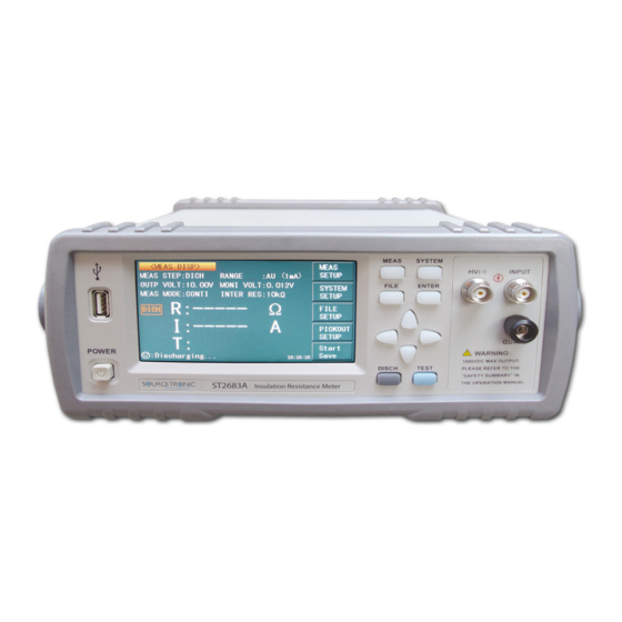
ST2683A Operation Manual Ver.1.3 2) Introduction to Front and Rear Panels This chapter will describe the basic operation of ST2683A. Before using the instrument, please read this chapter carefully. 2.1 Introduction to Front Panel Figure 2-1 shows the front panel of ST2683A. -
Page 9: Introduction To Rear Panel
There are four arrow keys: up, down, left and right arrow keys. 11) Trademark and Model Show instrument trademark and model. 12) POWER It is the power switch. 2.2 Introduction to Rear Panel Figure 2-2 shows the rear panel of ST2683A. RS-232C FOOT.C RATING FUSE 110V/60Hz... -
Page 10: Display Zone
PC can remotely control ST2683A through USB DEVICE. 2.3 Display Zone ST2683A adopts 24-bit 4.3-inch LCD touch screen with a resolution of 480*272. The display screen is divided into the following zones, as shown in figure 2-3. Figure 2-3 Display zone Page name This zone shows the current page name. -
Page 11: Introduction To Buttons On Front Panel
Press the [SYSTEM] button to enter into the <SYSTEM SETUP> page; the setup items of system can be changed on this page. 2.5 Simple Operation Simple operation steps for ST2683A: Use [MEAS], [SYSTEM] or [FILE] or soft keys to enter into the page required to enter. (Refer to ... -
Page 12: Starting Up
Figure 2-4 shows the boot screen of ST2683A, indicating product information such as instrument trademark, model and version. -
Page 13: Basic Operation
ST2683A Operation Manual Ver.1.3 3) Basic Operation 3.1 <MEAS DISP> Touch the screen or press down [MEAS] and then the <MEAS DISP> page will be displayed on the screen shown as figure 3-1. Figure 3-1 Measure Display The following functions can be achieved by touching the related key in soft key area on this page. -
Page 14: Measurement Functions
OUTP VOLT. MONI VOLT. MEAS MODE. INTER RES. 3.1.1 Measurement Functions Measurable parameters on ST2683A are as follows: Primary Parameters (Insulation resistance) (Leakage current) Secondary Parameter (Time count value of each procedure) The measurement results of primary parameters and secondary parameter are respectively displayed in three lines in the form of large characters. -
Page 15: Meas Setup
2. Touch this key again to enter into the soft keyboard and then input the required voltage and voltage range of 1~1000V (ST2683A four-digit significant figures), 1~500V (ST2683B four-digit significant figures) through number soft keyboard. Operation Procedures Two for setting the OUTP VOLT: Touch the output voltage zone needs to be modified on the screen and the following items will be displayed in the soft key zone. -
Page 16: Meas Mode
The commonly used several default voltage points of the instrument are: 1V, 10V, 25V, 50V, 75V, 100V, 125V, 150V, 200V, 250V, 500V (ST2683B), 750V (ST2683A), 1000V (ST2683A). 3.2.2 MEAS MODE This function is used for setting the measurement mode of the instrument. -
Page 17: Meas Speed
ST2683A Operation Manual Ver.1.3 Steps for setting the WAIT TIME, MEAS TIME and DICH TIME are the same as CHAR TIME. The setting range of CHAR TIME, WAIT TIME, MEAS TIME and DICH TIME is 0~999s. When the time is set to 0s, the step is skipped (details for measurement procedure please refer to 3.4.2). -
Page 18: Cont Chec
This function is used for setting the contact check of the instrument. As the unique contact check function of ST2683A/ST2683B, this function can well identify the contact performance of components for capacitance, cable and other capacitive materials and reduce the occurring of error test. -
Page 19: Average
ST2683A Operation Manual Ver.1.3 base obtained when operating this open clear; if the user operates the open clear unsuccessfully or sets the OPEN CLR as OFF, the clear base used in the instrument is the Factory Default. 2. When operating open clear, the user must conform to the condition described in Chapter One—“Environment”, pull out all the test lines in test terminals and heat the instrument for... -
Page 20: Meas Disp
Touch the soft key PICKOUT SETUP to enter into the <PICKOUT SETUP> page as shown in figure 3- Figure 3-3 PICKOUT SETUP The comparator functions of the instrument can be set on this page. ST2683A can set three groups of limit values for primary parameters. -
Page 21: Pick Item
ST2683A Operation Manual Ver.1.3 It is used for setting the PICK FUNC as ON. It is used for setting the PICK FUNC as OFF. Touch the corresponding key in soft key zone to select the relevant function. NOTE: The following steps can be operated under the premise of setting the PICK FUNC as ON. -
Page 22: Steps For Bin Disp
ST2683A Operation Manual Ver.1.3 BIN TWO It is used for setting that the buzzer will alarm when the test value passes BIN TWO. BIN STREE It is used for setting that the buzzer will alarm when the test value passes BIN STREE. -
Page 23: Steps For Outp Resu
ST2683A Operation Manual Ver.1.3 value according to the above steps. 3. Whether the PICK LIVA is set as ON or OFF, the priority level of BIN1, BIN2 and BIN3 keeps invariant. 3.3.7 Steps for OUTP RESU Touch the corresponding zone. The following items will be displayed in the soft key zone. - Page 24 ST2683A Operation Manual Ver.1.3 Figure 3-4 Test connection program NOTE: There is voltage output in HV (-) terminal. Please connect the DUT in discharged condition. Beware of electric shock. The device is not potential-free, so any voltage output from the HV (-) terminal is relative to ground.
-
Page 25: Operation Process
ON or OFF. Charge and discharge current is limited by the 1mA range’s 1kΩ charge resistor and also by an additional 5mA limit of the discharge circuit. 3.4.3 Range Selection There are six range resistances in ST2683A. They constitute six range segments (refer to figure 3-1 below). Range... -
Page 26: System Setup And File Manage
ST2683A Operation Manual Ver.1.3 4) System Setup and File Manage 4.1 System Setup Press [SYSTEM] to enter into the <SYSTEM SETUP> page as shown in figure 4-1. Figure 4-1 System Setup On this page, the following functions can be set: BEEPER, PASSWORD, BUS MODE, LANGUAGE, TRIGER, KEYSOUND, BAUD RATE, HANDLER VCC AND TIME. -
Page 27: Bus Mode
ST2683A Operation Manual Ver.1.3 Touch PASSWORD, the following soft key zone will be displayed: Touch this key to turn off the password protection function. This function would be disabled only when the preset password is correctly input. LOCK SYSTEM ... -
Page 28: Keysound
ST2683A Operation Manual Ver.1.3 You can touch soft keys to set corresponding functions. 4.1.5 KEYSOUND This function is used to control the key sound when the users touch the touch screen and press the machinery keys. Steps for setting the KEYSOUND: Touch KEYSOUND, the following soft key zone will be displayed: ... -
Page 29: Handler Vcc
ST2683A Operation Manual Ver.1.3 4.1.8 HANDLER VCC This function is used to control the VCC selection for handler interface of the instrument. Steps for setting the HANDLER VCC: Touch HANDLER VCC, the following soft key zone will be displayed: INTER ... -
Page 30: File Manage
Ver.1.3 4.2 <File Manage> ST2683A series can save parameters that are set by user to the internal non-volatile memory in the file format. User can load the file to use these parameters instead of resetting. This section will introduce the information about the function of Save/Recall. - Page 31 U disk. If the U disk memory exceeds 512M, it is recommended to use FAT32 standard to format the disk. 3. Before a U disk is connected to ST2683A, you are recommended to save the data on it and Sourcetronic will not be liable for the data loss.
- Page 32 ST2683A Operation Manual Ver.1.3 Figure 4-3 internal file page External file page is shown in figure 4-4 below: Figure 4-4 external file page Four files’ information will be displayed in the internal file page or the external file page, including file names and time of being saved.
- Page 33 U disk. Select Touch “Select”, the file the cursor locates will be selected. ST2683A can simultaneously copy several files to a U disk. Touch “Select” once again, the selected file will be cancelled from selection. Save Measurement Results In the “MEAS DISP”...
-
Page 34: Performance Index
ST2683A Operation Manual Ver.1.3 5) Performance Index 5.1 Measurement Function 5.1.1 Measurement Parameters and Notations R:Resistance I: Leakage current 5.1.2 Range Resistance Mode: AUTO, MANU (HOLD, UP, DOWN) 5.1.3 Trigger Manual, external, bus Manual: Press the “TRIGGER” button on the panel, the instrument will test a DUT once and display the result. -
Page 35: Display Digits
Correct to 0.1s 5.2 Test Signal 5.2.1 Output Voltage Range Max. output DVC range of ST2683A test terminal: 1 – 1000V. Max. output DVC range of ST2683B test terminal: 1 – 500V. 5.2.2 Output Voltage Accuracy Voltage ≥ 10V: 1% ± 1V Voltage <... -
Page 36: Measurement Accuracy
ST2683A Operation Manual Ver.1.3 5.3 Measurement Accuracy Measurement accuracy depends on measurement stability, temperature coefficient, linearity, repeatability and correction interpolation error. Checking the measurement accuracy should be taken under the following circumstances: a. Warm-up time should be more than 30 minutes. -
Page 37: Remote Control
EIA in 1969, which rules to send one bit in a data line every time. As most serial interfaces, the serial interface of ST2683A is also not strictly based on RS-232 standard but only uses the smallest subset of this standard. The signals are listed in the following table. -
Page 38: Scpi (Standard Commands For Programmable Instruments)
LabView or equivalent installed to use this type of connection. 6.3.1 System Configuration Connect USB interfaces on PC and ST2683A through a USB cable. 6.3.2 Install the Driver When ST2683A is first connected to a PC through a USB cable, the prompt information –Found... - Page 39 ST2683A Operation Manual Ver.1.3 New Hardware will show on the right bottom of the computer desktop, as is shown below: Figure 6-3 Procedure 1 of Installing USB Driver Click “NEXT”, dialogue 6-4 will pop up. Choose “Install the software automatically (recommended)”.
-
Page 40: Usbvcom Virtual Serial Port
When “USBVCOM” is selected, the USB interface can be configured as a virtual serial port (VCom). 6.4.1 System Configuration Connect PC and ST2683A to the USB interface through a USB cable. 6.4.2 Installing Driver Methods of installing USBCDC driver are the same with that of installing USBTMC driver. Windows 10 will install the driver automatically from Windowsupdate without the need of any driver package when the computer is connected to the internet. -
Page 41: Scpi Command Reference
NR1 : integer, for example:123 NR2 : fixed number, for example: 12.3 NR3 : floating number, for example: 12.3E+5 NL : CR character, integer: 10 ^END: EOI (end) signal of IEEE-488 bus. 7.2 ST2683A Subsystem Commands ●DISPlay ●TRIGger ●COMParator ●DISCharge ●SYSTem... -
Page 42: Function Subsystem Commands
ST2683A Operation Manual Ver.1.3 For example: WrtCmd(“DISP:PAGE MEAS”); Set the display page to measurement display. Query syntax: DISPlay:PAGE? Return format: <page name><NL^END> <page name> refer to the above set value. 7.2.2 FUNCtion Subsystem Commands FUNCtion subsystem commands are mainly used to set the items relating to MEAS SETUP: “voltage”, “measurement mode”, “charge time”, “wait time”, “measurement time”, “discharge time”, “range”,... - Page 43 ST2683A Operation Manual Ver.1.3 current zero clearing passes or fails. If this zero clearing passes, the zero base used in this measurement is obtained from this open zero clearing; if this zero clearing fails, the zero base used in this measurement is factory default.
- Page 44 ST2683A Operation Manual Ver.1.3 SINGle Return Format: <NL^END> CONTinuous The :FUNCtion: MMODe? query returns to the current measurement mode of the instrument. The : MSPeed command sets the measurement speed of the instrument. The :FUNCtion:MSPeed? query returns to the measurement speed of the instrument.
- Page 45 ST2683A Operation Manual Ver.1.3 For example: WrtCmd(“FUNCtion:CTTM 12.5”); set the charge time of the instrument as 12.5s. Query syntax: FUNCtion: CTTMe? Return Format: <value><NL^END> The :FUNCtion:CTTMe? query returns to thecharge time of the instrument. The :WTIMe command set the wait time of the instrument.
- Page 46 ST2683A Operation Manual Ver.1.3 Where, <value> is any integer value among the average times range (1-999) of the instrument. For example: WrtCmd(“FUNCtion:AVERage 12”); set the average times of the instrument as 12. Query syntax: FUNCtion: AVERage? Return Format: <value><NL^END> The :FUNCtion:AVERage? query returns to the average times of the instrument.
-
Page 47: Discharge Subsystem Commands
ST2683A Operation Manual Ver.1.3 Return format: <NL^END> 7.2.3 DISCharge Subsystem Commands DISCharge [:GO] Set the instrument to discharge. 7.2.4 TRIGger Subsystem Commands The TRIGger subsystem commands set the instrument trigger source and the delay time after triggering, and triggers instrument measurement. -
Page 48: Fetch? Subsystem Commands
ST2683A Operation Manual Ver.1.3 7.2.5 FETCH? Subsystem Commands The FETCh? Subsystem commands are used to get the measurement result of ST2683A. Command Tree: The [:IMP]? query returns ST2683A’s last measurement result to its output buffer. Query syntax: FETCh[:IMP]? For example, WrtCmd (“TRIG:SOUR BUS”);... -
Page 49: Comparator Subsystem Commands
Data format: <insulation resistance>, <leakage current>, <ultralimit> Ultralimit: downlap between the range onlap AUTO command makes ST2683A to send each measurement result to its output buffer automatically. Command syntax:FETCh:AUTO For example: WrtCmd(“FETC:AUTO ON”); The SMONitor command querys the monitor voltage. - Page 50 ST2683A Operation Manual Ver.1.3 Command syntax: ON(1) COMParator:FUNCtion OFF(0) Where, Character 1 (integer:49) means ON. Character 0 (integer: 48) means OFF. For example: WrtCmd(“COMP:FUNC ON”) Query syntax: COMParator:FUNCtion ? Return format: <NR1><NL^END> The :ITEM command sets the pickout item of the instrument.
- Page 51 ST2683A Operation Manual Ver.1.3 :BEEPer BONe BTWo BSTRee The above commands are used to specify the indication of beeper toward pickout results or turn off the beeper function. Command syntax: COMParator:BEEPer BONe it beeps when the beeper passes BIN1 COMParator:BEEPer...
-
Page 52: System Subsystem Commands
ST2683A Operation Manual Ver.1.3 For example: WrtCmd(“COMP:BLIM ON”) Query Syntax: COMParator: BLIMitvalue? Return format: <NR1><NL^END> The :ORESultcommand sets the bin output results type of the instrument. COMParator:ORESult? query returns to the current bin output results type. Command syntax: LEVel COMParator:ORESult... -
Page 53: Mass Memory Subsystem Commands
ST2683A Operation Manual Ver.1.3 The :SYSTem:BEEP OFF (0) and ON (1) commands are used to set and query the system beeper of the instrument. For example: SYST:BEEP 0 turn off the beeper Query Syntax: SYST:BEEP? Return format: 0 or 1... -
Page 54: Gpib Common Comamnds
The *TRG command triggers the measurement and then sends the result to the output buffer. Command syntax: *TRG For example: WrtCmd(“*TRG”); NOTE: ”*trg” will be valid when :INIT:CONT ON and trig:sour bus commands are enabled. The *IDN? query returns ST2683A’s identification string. Query syntax: *IDN? Return format: <manufacturer>,<model>,<firmware><NL^END> Where, <manufacturer>... -
Page 55: Handler Interface
Ver.1.3 8) Handler Interface ST2683A Insulation Resistance Meter equips with a Handler interface which is mainly used to output the sorting result. When the instrument is applied to an automatic component sorting test system, this interface will output the handshake signal and the sorting result output signal. The sorting result output corresponds to the comparison result output of the current comparator bin. - Page 56 ST2683A Operation Manual Ver.1.3 Programmable Handler sequence chart (OUTP RESU is set as PULSE)
- Page 57 ST2683A Operation Manual Ver.1.3 Time Min. value Max.value Trigger pulse width Tip time when measurement ended (EOC) 10ms Interval time between two triggers 1 Sampling Time Sampling Time = above 30ms FAST Above 60ms SLOW Electrical Characteristics DC isolated output Each DC output (pins 1 through 5) is opened by a collector, output and isolated by a photoelectric coupler.
-
Page 58: Package Contents And Warranty
ST2683A Operation Manual Ver.1.3 9) Package Contents and Warranty 9.1 Package Contents Following items should be contained in the package. ST2683A series instrument Test cable (ST26004B) Three-Wire power line Fuse (1A/2A) 1 of each Operation Manual Manufacturer Certificate Test Report Warranty Card Verify that you have received all above items and any optional accessories you may have ordered. -
Page 59: Shipping
This warranty does not apply in the event of misuse or abuse of the product or as a result of unauthorized alterations or repairs. Sourcetronic will, without charge, repair or replace, at its option, defective product or component parts. - Page 60 SOURCETRONIC GMBH Fahrenheitstrasse 1 28359 Bremen Germany T +49 421 2 77 99 99 F +49 421 2 77 99 98 info@sourcetronic.com www.sourcetronic.com skype: sourcetronic www.sourcetronic.com...
Need help?
Do you have a question about the ST2683A and is the answer not in the manual?
Questions and answers