
Related Manuals for Sourcetronic ST2684


Summary of Contents for Sourcetronic ST2684
- Page 1 SOURCETRONIC − Qualitäts-Elektronik für Service, Labor und Produktion Manual Insulation resistance meter ST2684A...
- Page 2 ST2684/A Operation Manual Ver1.01 Manual Printing History The manual’s printing date indicates its current edition. The printing date changes when a new edition is printed. (Minor corrections and updates that are incorporated at reprint do not cause the date to change.) The manual edition changes when extensive technical changes are incorporated.
- Page 3 ST2684/A Operation Manual Ver1.01 Safety Cautions: The instrument is class I. Make sure that there is a ground Ground connection in the mains outlet. Failure to do this may cause personnel injury because of the existence of static or induced electricity on the instrument cover.
-
Page 4: Table Of Contents
ST2684/A Operation Manual Contents Contents Chapter 1 Introduction ........................1 1.1 Introduction ..........................1 1.2 Service conditions ........................1 1.2.1 Power .......................... 1 1.2.2 Enviromental temperature and humidity ................1 1.2.3 Warm-up ..........................1 1.2.4 Cautions ........................2 1.3 Dimension and weight ......................... 2 1.4 Safety ............................ - Page 5 ST2684/A Operation Manual Contents Chapter 4 [SETUP] .......................... 22 4.1 <MEASURE SETUP> ......................22 4.1.1 RESULT .......................... 23 4.1.2 HV2 TRACK ........................23 4.1.3 DISCHARGE ........................24 4.1.4 MEASURE DELAY ....................... 24 4.1.5 CHARGE TIME ......................25 4.1.6 HUM REJECT ........................ 26 4.1.7 CONTACT CHECK ......................
- Page 6 ST2684/A Operation Manual Contents 5.1 <SYSTEM SETUP> ........................51 5.1.1 L CD contrast ........................51 5.1.2 LCD Style ........................51 5.1.3 Pass beeper ........................52 5.1.4 Fail beeper ........................52 5.1.5 Language ......................... 53 5.1.6 Handler ..........................53 5.1.7 Password ......................... 53 5.1.8 Bus mode ........................
- Page 7 ST2684/A Operation Manual Contents 8.4.2 Install drive ........................82 Chapter 9 Command Reference ....................... 83 9.1 GPIB common commands for ST2684 ..................83 9.2 Command structure ......................85 9.3 Command syntax ........................86 9.4 Input format ..........................86 9.5 SCPI commands ........................87 9.5.1 System commands......................
-
Page 8: Chapter 1 Introduction
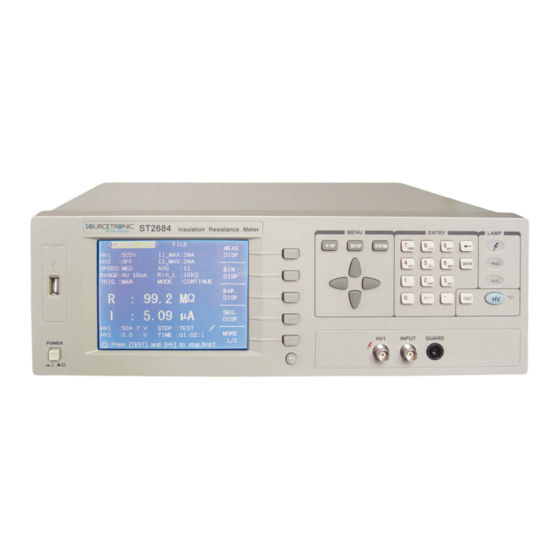
1.1 Introduction ST2684/ST2684A is an insulation resistance meter that is high in speed and accuracy. It bears the advantages of LCD display, user-friendly menu, simple operations and great conveniences. Interfaces, such as USB, HANDLER RS232C, scanning and IEEE488 (optional) are available, making it possible for the instrument to be used in an automatic sorting system and PC remote control operations. -
Page 9: Cautions
If this cannot be arranged, please make sure to use power filter for the instrument. (4) ST2684/2684A has the cooling fan on the rear panel and cooling holes on both sides. High temperature inside will decrease the measurement accuracy, so sufficient space must be kept around the instrument to avoid obstructing the air flow of the cooling fans. -
Page 10: Electromagnetic Compatibility
ST2684/A Operation Manual Chapter 1 Introduction 1.5 Electromagnetic compatibility Power instantaneous sensitivity is based on GB6833.4. Transmission sensitivity is base on GB6833.6. Radiated interference is based on GB6833.10. -
Page 11: Chapter 2 Introduction To Front And Rear Panels
ST2684/A Operation Manual Chapter 3 [DISP] Chapter 2 Introduction to Front and Rear Panels 2.1 Introduction to front panel Figure 2-1 Front Panel Introduction to the front panel is as follows: Table 2-1 Introduction to the front panel Name Introduction... - Page 12 ST2684/A Operation Manual Chapter 3 [DISP] instrument is set in manual trigger mode. The indicator lights up when the voltage across HV indicator() the two test terminals is higher than 0.4V; otherwise it is off. The indicator lights up when the limit setup PASS indicator requirements are met;...
-
Page 13: Introduction To Rear Panel
Provide the universal serial communication interface for instrument and external device. All RS232C parameter setup and command are set and obtained by computer to realize the remote control. DEVICE PC can control ST2684 through the USB... -
Page 14: Display Zone
Label plate Record the date, model, manufacturer, etc. 2.3 Display zone ST2684 adopts a 320×240 dot-matrix LCD. The display screen is divided into the following zones, as shown in figure 2-3. Main menu Indicate the name of the currently displayed page. -
Page 15: Main Menu Keys And Their Corresponding Display
The following item will be displayed: <SYSTEM SETUP> 2.5 Basic operations Basic operations for ST2684 are as follows: Press [DISP], [SETUP] or [SYSTEM] and select softkeys to enter into the desired page to display (see figure 2-5). -
Page 16: Start-Up
Turn on the instrument by pressing the power switch on the bottom left corner of the front panel. The boot screen will be displayed. Figure 2-4 shows the boot screen of ST2684 including our trade mark, instrument model (ST2684) and the software version (Ver. 1.0.0): If the password protection is enabled, you will be required to input your password. -
Page 17: Chapter 3 [Disp]
ST2684/A Operation Manual Chapter 3 [DISP] Chapter 3 [DISP] 3.1 <MEASURE DISP> Press [DISP] to enter into <MEASURE DISP>, as is shown in figure 3-1. Figure 3-1 Measurement Display Page The measurement result will be displayed in large character in this page. The following measurement parameters can be set in this page. -
Page 18: Hv1
ST2684/A Operation Manual Chapter 3 [DISP] STEP TIME ———————————————————————————————————— NOTE: In <MEASURE DISP>, press [TEST] to start or stop the test; press [HV] to start or stop the high voltage output. ———————————————————————————————————— 3.1.1 HV1 This function is used to set the voltage output of HV1. -
Page 19: Hv2
Press one of above softkeys to set the charge current. 3.1.3 HV2 HV2 output is available only on ST2684 but not on ST2684A. This function is used to set the voltage (preset voltage) output of HV2. There are two voltage settings available: voltage independent mode (HV2 TRACK: OFF) and voltage track mode (HV2 TRACK: ON). -
Page 20: I2_Max
200 mA 2)Press one of the above softkeys to set the charge current. 3.1.5 SPEED Following factors decide the measurement speed of ST2684/A: Integration time (A/D conversion) Average times (Average test times) Measurement delay time (the time from instrument start-up to test starting) ... -
Page 21: Average (Avg)
ST2684/A Operation Manual Chapter 3 [DISP] 3.1.6 Average (AVG) ST2684/A can average results of two or more measurings. The average times ranges from 1 to 100 by a resolution of 1. Operational steps for the average times setting: Move the cursor to AVG, the following items will be displayed in the softkey zone: ↑(+)... -
Page 22: Trig
Bus mode can not be set on the front panel of the instrument. ———————————————————————————————————— NOTE: If a trigger signal is received by ST2684 in the phase of test, it will be ignored. Therefore, trigger signals can be sent to ST2684 when the test ends. -
Page 23: Mode
ST2684/A Operation Manual Chapter 3 [DISP] 3.1.10 MODE ST2684/A has 2 test modes: SINGLE and CONTINUE. In SINGLE mode and by pressing [TEST] one time, the instrument makes a test in the following sequence of trigger, charge, wait, test and end test. -
Page 24: File
ST2684/A Operation Manual Chapter 3 [DISP] pressing [HV], it will start or stop the high voltage output. ———————————————————————————————————— 3.2.1 FILE See 5.2 for details about the <FILE MANAGE> function. 3.3 BARGRAPH DISP Press [DISP] and select BAR. DISP to enter into the <BARGRAPH DISP> page. -
Page 25: Bar Scale
Press [SETUP] and select RESULT, CURR should be chosen in the softkey zone. Move the cursor back to <MEASURE SETUP> and enter into the <BARGRAPH SETUP> page, the bar scale of the current range can be set. When ST2684/A is in CURR mode, the setting range ranges from 0 to 8. 0: AUTO SCALE (automatically select scale) 1: 1pA –... -
Page 26: File
ST2684/A Operation Manual Chapter 3 [DISP] 2) User can input the desired bar scale number by numeric keys and press [ENTER] to end inputting. ——————————————————————————————— NOTE: Switching the output result (resistance or current), the bar scale number will reset to 0, that is to select the scale automatically. -
Page 27: Xy Graph
ST2684/A Operation Manual Chapter 3 [DISP] 3.5 XY GRAPH [DISP] → MORE 1/2→ XY GRAPH→ <XY GRAPH> Figure 3-5 displays a XY curve tested with no load, where, the shape of the curve is affected by the environment. This page is a single display page which can be set in the <XY SETUP> page. -
Page 28: File
ST2684/A Operation Manual Chapter 3 [DISP] ———————————————————————————————————— NOTE: In <SCAN DISP>, pressing [TEST], the instrument will start or stop a test; pressing [HV], it will start or stop the high voltage output. ———————————————————————————————————— 3.6.1 FILE See 5.2 for details about the <FILE MANAGE> function. -
Page 29: Chapter 4 [Setup]
ST2684/A Operation Manual Chapter 4 [SETUP] Chapter 4 [SETUP] 4.1 <MEASURE SETUP> Press [SETUP] to enter into the <MEASURE SETUP> page. Figure 4-1: The following parameters can be set on <MEASURE SETUP>. HV1 output (HV1) I1 maximum charge current(I1_MAX)... -
Page 30: Result
This function is exclusive to ST2684 and not available to ST2684. Two modes are available to the HV2 output of ST2684: independent mode (OFF) and track mode (ON). When the mode is set to independent mode (turn the track function off), the voltage of HV2 will be output independently and can be set to any value. -
Page 31: Discharge
2) Use above softkeys to set HV2 TRACK to ON or OFF. 4.1.3 DISCHARGE When the test is finished, ST2684/A can be set to turn on or off the discharge function. ———————————————————————————————————— NOTE: This function is only applicable to single mode. -
Page 32: Charge Time
When [ENTER] is used to confirm inputting, the default unit is S. 4.1.5 CHARGE TIME The charge time on ST2684/A can be set. This function can ensure capacitive components are charged rapidly and speed the test. If CHARGE TIME is set, the input amplifier will be shorted by a 1Ωresistance. -
Page 33: Hum Reject
ST2684/A Operation Manual Chapter 4 [SETUP] 4.1.6 HUM REJECT For the difference of external source, it is essential to toggle the power frequency so as to ensure the test accuracy. The power frequency can be toggled between 50Hz (the default frequency) and 60Hz. -
Page 34: Comp: On/Off
4.2.1 COMP: ON/OFF ST2684/A can set limits for 4 bins. The measure result can be divided into up to 5 bins (from BIN1 to BIN2). If ST2684 has installed a HANDLER interface and is used in an automatic test sorting system, the comparator function will be quite useful. -
Page 35: Limit Mode Of Compare Function
ST2684/A Operation Manual Chapter 4 [SETUP] Operational steps for comparator function ON/OFF: Move the cursor to COMP, the following softkeys will be displayed. Use above softkeys to set the comparator function ON or OFF. 4.2.2 Limit mode of compare function Compare function provides two modes as shown in figure 4-2-1. -
Page 36: Setting Nominal Value
4.2.4 High and low limits ST2684/A can set the limits for 4 bins. The test result is sorted to 5 bins at most (from BIN1 to BIN5). High and low limits can be set in HIGH and LOW zones from BIN1 to BIN5. -
Page 37: File Manage
ST2684/A Operation Manual Chapter 4 [SETUP] default unit is the same as that input last time. After inputting the low limit value of bin1, the cursor is jumped to HIGH of bin1. Input the high limit of bin1. The cursor is jumped to HIGH of bin2. As the limit mode of compare function is sequential mode, the low limit of bin2 is equal to the high limit of bin1. -
Page 38: Bar Scale
ST2684/A Operation Manual Chapter 4 [SETUP] In the <BARGRAPH SETUP> page, the following control parameters can be set in this page: BAR SCALE (Select the serial number) FILE 4.3.1 BAR SCALE There are two bar scale setups: RES (resistance) and CURR (current). -
Page 39: File
ST2684/A Operation Manual Chapter 4 [SETUP] 100GΩ – 10TΩ 1TΩ – 100TΩ 10TΩ – 1PΩ Operational steps for setting bar scale: 1) Move the cursor to BAR SCALE, the following softkeys will be displayed: ↑(+) This key is used to increase the serial number of bar graph. -
Page 40: Selected Seq
ST2684/A Operation Manual Chapter 4 [SETUP] The following control parameters can be set in the <SEQUENCE SETUP> page: Select the sequence number (SELECTED SEQ.) DEFAULT SEQ. User SEQ. FILE 4.4.1 SELECTED SEQ. It is used to select the reference test sequence for the <SEQUENCE DISP> page. -
Page 41: User Seq
ST2684/A Operation Manual Chapter 4 [SETUP] limit is met. At 20s or 60s, if the low limit cannot be met, the measure will stops like that happens at 20 SEC SEQ. or 60 SEC SEQ... Operational steps for setting the default sequence: 1)... -
Page 42: Seq. Content
———————————————————————————————————— 4.5.1 Basic test theory and specifications ST2684/A can be programmed to run a sequence of measurements after being triggered from the keyboard or remotely. The measurements can be compared with limits and set the bin out signals to approve or reject the device under test. - Page 43 ST2684/A Operation Manual Chapter 4 [SETUP] Input Resister ( 10k or 1M ) Change Relay Figure 4.5.1 Test Schematic Diagram Figure 4.5.1 shows the HV supply and the input stage of the current amplifier. The test object is a capacitance.
-
Page 44: Item
ST2684/A Operation Manual Chapter 4 [SETUP] The charge relay is activated during the preset charge time, which is longer than it takes for the current to fall below 2mA. When the charge time expires, the charge relay is deactivated. Immediately after this the measured current is very low (and hence the calculated resistance very high), but in the period after the absorption current begins to flow through the capacitor. - Page 45 NOTE: User can decide to set the HIGH/ LOW limit or not. If both limits or either one are set, ST2684/A will automatically switch on the compare function. Likewise, if both limits are not set, the compare function will be automatically switched off.
- Page 46 NOTE: User can decide to set the HIGH/ LOW limit or not. If both limits or either one are set, ST2684/A will automatically switch on the compare function. Likewise, if both limits are not set, the compare function will be automatically switched off.
- Page 47 Insert a blank line and uplift the data in the next line. 2> Use above softkeys to achieve relative operations. 4.5.4 HV Voltage setting range: ST2684: 10 ---- 500V ST2684A: 10-----1000V ———————————————————————————————————— NOTE: Whether set HV or not depends on the selected sequence command.
-
Page 48: Rang
ST2684/A Operation Manual Chapter 4 [SETUP] 100V,250V,500V,1000V. ↑(+) This is a fine adjustment softkey used to increase the voltage by 1V. ↓(-) This is a fine adjustment softkey used to decrease the voltage by 1V. ↓(--) This is a coarse adjustment softkey used to decrease the voltage in accordance with the sequence of some common-used voltage points. -
Page 49: Low, High
1. User can decide to set the HIGH/ LOW limit or not. If both limits or either one are set, ST2684/A will automatically switch on the compare function. Likewise, if both limits are not set, the compare function will be automatically switched off. -
Page 50: Time
Use above softkeys to set the time, or numerical keys and [ENTER] to input the desired time. By the latter way, when ms is selected and the input time is not a multiple of 10, ST2684/A will set the time to a value that approximate to a multiple of 10;... -
Page 51: X-Scale
ST2684/A Operation Manual Chapter 4 [SETUP] The following parameters can be set in the <XY GRAPH SETUP> page: ■ Select the X-scale (X-SCALE) ■ Set time (SET TIME) ■ Select the Y-scale (Y-SCALE) ■ Current scope (CUR SCOPE) 4.6.1 X-SCALE Select the X-scale of the XY graph. -
Page 52: Y-Scale
ST2684/A Operation Manual Chapter 4 [SETUP] 2) Use above softkeys to set the total test time, or numerical keys and [ENTER] to input the time. By the latter way, the default unit will be s. 4.6.3 Y-SCALE Operational steps for setting the Y-scale: 1)Move the cursor to Y-SCALE, the following softkeys will be displayed:... -
Page 53: Scan Setup
ST2684/A Operation Manual Chapter 4 [SETUP] 4.7 SCAN SETUP Press [SETUP], and then MORE 1/2 and SCAN SETUP to enter into the <SCAN SETUP> page. Figure 4-7: The following parameters can be set in the <SCAN SETUP> page: ■ SELECTED SEQ. -
Page 54: Scan Start Num
ST2684/A Operation Manual Chapter 4 [SETUP] USER3 USER4 MORE 2/2 3)If the desired sequence is missed, repeat step1 and step 2 to select the desired one. 4.7.2 SCAN START NUM There are 32 scan channels at most and the number ranges from 0 to 31. -
Page 55: Scan Connect
ST2684/A Operation Manual Chapter 4 [SETUP] This softkey is used to set the display mode as PASS/ FAIL. (2)Use above softkeys to set the scan result display mode. 4.7.5 SCAN CONNECT This zone is used to check the scanner is connected correctly or not. -
Page 56: Open Corr:on/Off
ST2684/A Operation Manual Chapter 4 [SETUP] LOAD CORR ■ REFERENCE ■ FILE ■ 4.8.1 OPEN CORR:ON/OFF This function sets whether to take the open correction value into account when the measure is taken. OPEN CORR: ON Take the open correction value into account. -
Page 57: Load Corr: On/ Off
ST2684/A Operation Manual Chapter 4 [SETUP] 4.8.3 LOAD CORR: ON/ OFF LOAD CORR: ON Take the open correction value into account. LOAD CORR: OFF Do not take the open correction value into account. Operational steps for switching on or off the load correction function: (1)Move the cursor to LOAD CORR, the following softkeys will be displayed:... -
Page 58: Chapter 5 [System]
ST2684/A Operation Manual Chapter 5 [SYSTEM] Chapter 5 [SYSTEM] 5.1 <SYSTEM SETUP> Press [SYSTEM], then [SYSTEM SETUP] to enter into the <SYSTEM SETUP> page. Figure 5-1: This page includes LCD contrast, beeper, alarm, language, password, bus mode, bus address, etc. -
Page 59: Pass Beeper
ST2684/A Operation Manual Chapter 5 [SYSTEM] CLASSIC This softkey is used to set the LCD style to classic display mode. DEFAULT This softkey is used to set the LCD style to default mode. 5.1.3 Pass beeper Set the pass beep mode. -
Page 60: Language
This softkey is used to modify the password. The instrument will prompt user to input old password, new password and to confirm the new password until the modification is done. ———————————————————————————————————— NOTE: The default password for ST2684 is 2684. ————————————————————————————————————... -
Page 61: Bus Mode
ST2684/A Operation Manual Chapter 5 [SYSTEM] 5.1.8 Bus mode Set RS232C interface or GPIB interface as the interface bus. See chapter 8 Remote Control for details. Operational steps for setting the bus mode: Move the cursor to BUS MODE, the following softkeys will be displayed: RS232C ... -
Page 62: Time
Pressing the right and the left arrow keys on the keyboard, the cursor will toggle among different time zones. 5.2 <FILE MANAGE> ST2684 series can save parameters that are set by user to the internal non-volatile memory in file format. User can load the file to use these parameters instead of resetting. -
Page 63: Sta
If the U disk memory exceeds 512M, it is recommended to use FAT32 standard to format the disk. 3. Before a U disk is connected to ST2684, you are recommended to save the data on it and Sourcetronic GmbH will not be liable for the data loss. - Page 64 ST2684/A Operation Manual Chapter 5 [SYSTEM] HV2 fine adjustment voltage I 1_MAX I 2_MAX SPEED Timer interval RANGE R in_L TRIG MEASURE DELAY MEASURE DELAY unit CHARGE TIME ...
-
Page 65: Operational Steps For File Manage
ST2684/A Operation Manual Chapter 5 [SYSTEM] Parameters in <SCAN SETUP>: SELECTED SEQ. SCAN START NUM SCAN END NUM SCAN RESULT 5.2.2 Operational steps for file manage A. Check the existed file: Press FILE and then FILE MANAGE to enter into the <FILE MANAGE> page. - Page 66 ST2684/A Operation Manual Chapter 5 [SYSTEM] B. Load the existed file (*.STA) to the instrument: (1) Move the cursor the file to be loaded; (2) When the LOAD softkey is pressed, the instrument will display a prompt information “Are you sure load NO.? (Note: NO.
- Page 67 ST2684/A Operation Manual Chapter 5 [SYSTEM] In external file list (E:), operation for folder can be taken. A: Enter the subdirectory by the following steps (1) Move the cursor the desired folder; (2) Press the SUB DIR softkey to enter the subdirectory;...
-
Page 68: Chapter 6 Measurement Procedures And Examples
H.T. Shielding of Testfixture Guard ST2684A can supply up to 1000V (10 mA) on DUT. ST2684 can supply up to 500V (200 mA) on DUT. 6.3 Example for automatic testing Wiring diagram for single-circuit power supply: Figure 6.3.1... - Page 69 ST2684/A Operation Manual Chapter 6 Measurement Procedures and Examples Measure current in HT OUT Discharge Precharge Charge Measure Single supply Wiring diagram for double-circuit power supply: Figure 6.3.2 Measure current in Precharge Charge Measure Dual supply...
-
Page 70: Insulation Testing Of Capacitors
ST2684/A Operation Manual Chapter 6 Measurement Procedures and Examples 6.4 Insulation Testing of Capacitors There are some limiting factors to be considered when measuring the Insulation Resistance of High Quality Capacitors. There is a maximum value of obtainable insulation Resistance depending on the capacitance value and the applied test voltage. - Page 71 ST2684/A Operation Manual Chapter 6 Measurement Procedures and Examples insulations resistance Capacistance...
-
Page 72: Charge Resistors For Automated Ir Testing
The latter makes it necessary to ensure that the capacitor is fully charged before measurement. This application note describes the fundamental of calculating the charge resistor values. General Fig. 6.5.1 shows the set-up for ST2684 with two HV supplies, one for precharging and one for fine charging and measurement. Current Measurement Board... - Page 73 10-20 times Rpr1 and Rpr3. The fine charge resistors should match the input resistance Ri of the current input amplifier. In ST2684/ST2684A IR tester, this resistor can be switched to either 10kΩ or 1MΩ. In figure 6.5.1 only two fine charge stations are shown, in many cases more than 10 stations are preferred.
- Page 74 Wiring and installation in sorting machine When installing the ST2684/ST2684A IR tester and charge resistors in sorting machines, great care should be taken in the wiring. The general rule is to avoid electrical loops that can pick up magnetic noise fields (hum) and add self-inductance.
- Page 75 ST2684/A Operation Manual Chapter 6 Measurement Procedures and Examples Figure 6.5.2 Wiring of sorting machine The precharge stations are supplied from HV2. The return path of the charge current must be the HV2 return and each precharge station must have its own return wire. In this way it is possible to ensure parallel wiring of the complete path from tester to each precharge station.
-
Page 76: Insulation Resistance Measurement
Connecting ST2684/ST2684A series Insulation Resistance Tester When connecting the ST2684/ST2684A to the DUT, there are few issues to address to ensure safety, noise free measurement, and minimum disturbance of the surroundings and long term stability of the instrument. The general rule is to avoid electrical loops that can pick up magnetic noise fields (hum) and add self-inductance. - Page 77 ST2684/A Operation Manual Chapter 6 Measurement Procedures and Examples or unstable connection can lead to high-current flashes during the (attempted) charging of DUT. The best way to protect against flashovers is to place wire wound resistors as close as possible to the DUT. In this way the transients resulting from the flashovers are damped near the source.
- Page 78 After the measurement the capacity has to be discharged. In ST2684/2684A, this is done by switching the output to a 2kΩ/5W wire wound resistor. The stored energy in a capacitor is calculated from: At 500V this limits the capacity that can be discharged by the internal resistor to 4mF.
-
Page 79: Examples For Sequence Test
ST2684/A Operation Manual Chapter 6 Measurement Procedures and Examples Range 6: 1nA – 10nA; Range 7: 10pA – 1nA; The correct range is established from measuring the leakage current on several known good and known bad components at the specified voltage and charge/dwell/soak time. The range to choose is the most sensitive range that does not lead to overflow at the upper limit of the leakage current. -
Page 80: Chapter 7 Test Performance
ST2684/A Operation Manual Chapter 7 Test Performance Chapter 7 Test Performance 7.1 I.R./L.C. TEST 7.1.1 Measurement parameters IR test: I.R.(Isolated Resistance), L.C.(Leakage Current) 7.1.2 General specifications General specifications Model ST2684 ST2684A Operating temperature and 10℃ - 40℃, ≤ 90% RH... -
Page 81: Specifications
ST2684/A Operation Manual Chapter 7 Test Performance 7.1.3 Specifications Resistance test ST2684 ST2684A Range 10 kΩ– 50TΩ 10 kΩ– 100TΩ Accuracy I > 100pA: 2% I ≤ 100 pA: 2% ± Vtest/2pA Current test Range Range 1: 100µA – 1mA, Internal input impedance 10 kΩ... -
Page 82: Safety Summary
ST2684/A Operation Manual Chapter 7 Test Performance 7.2 Safety summary 7.2.1 Insulation resistance (IR) Referring to the working condition, the insulation resistance of the power terminal and the case should not be less than 50MΩ. Under the damp and heat condition, the insulation resistance should not be less than 2 MΩ. -
Page 83: Chapter 8 Remote Control
Signal ground common As most serial interfaces worldwide, the serial interface of ST2684/ST2684A is also not strictly based on RS-232 standard but only uses the smallest subset of this standard. The signals are listed in the following table. Table 7-2 RS-232 signal and pin number... -
Page 84: Communicating With Pc
ST2684/A Operation Manual Chapter 8 Remote Control Note: The definition for serial interface pin used by the instrument is different from that of standard 9 pin connector. RS232C used on this instrument applies 9-pin DB socket, and the sequence of pin is as follows: (side view)... -
Page 85: Gpib Interface Operation
ST2684/ST2684A applies IEEE488.2 and the interface plate can be optionally purchased by user. Control command system is open so that user can use the PC operation interface provided by ST2684/ST2684A or take measurements by the control command system. The control command system supports most functions of the instrument, that is to say, user can execute almost all operations on PC. - Page 86 ST2684/A Operation Manual Chapter 8 Remote Control exceed 20 meters. A maximum of 15 devices can be connected on one bus system. There are no restrictions on how the cables are connected together. However, it is recommended that no more than four piggyback connectors be stacked together on any one device.
-
Page 87: Gpib Interface Capability
SRQ, deemed as an interruption, will inform the controller to prepare the transmitted data or that errors exist on the instrument. As soon as ST2684/ST2684A sends a SRQ service request signal, it will set the status byte to 6. 6 bytes are RQS request service bytes and sometimes connects with serial poll to act as the status byte. -
Page 88: Scpi(Standard Commands For Programmable Instruments
Use USB cable to connect the USB interface on the rear panel to USB port. 8.3.2 Install drive When using USB to connect ST2684 with computer at first time, the computer will note: “New hardware is found”, then as figure 0-2: Figure 0-2 Press “Next”,as shown in figure 0-3,select “Install from list or appointed position”. -
Page 89: Usbcdc Virtual Serial Port
When “USBCDC” is selected, the USB interface can be configured as a virtual serial port (VCom). 8.4.1 System configuration Connect PC and ST2684/ST2684A to the USB interface through a USB cable. 8.4.2 Install drive The method of installing USBCDC drive is the same as that of USBTMC,but when selecting driving file, select the path of usbVCom.inf,as Figure 0-6. -
Page 90: Chapter 9 Command Reference
<firmware> software version (VER1.0.0) For example: WrtCmd (“*IDN?”); *TST? is used to query self-test, to perform internal self-test and generate the error message report. For ST2684, if the query result is “0”, there is no error. Query syntax: *TST? Return format: 0<NL^END>... - Page 91 ST2684/A Operation Manual Chapter 9 Command Reference Description Power On(PON) Bit User Request(URQ) Bit Command Error(EME) Bit Execution Error(EXE) Bit Device Dependent Error(DDE) Bit Query Error(QYE) Bit Request Control(RQC) Bit Operation Complete(OPC) Bit Query syntax: *ESE? Return format: <value><NL^END> For example: WrtCmd (“*ESE?”);...
-
Page 92: Command Structure
Always 0(zero) For example: WrtCmd (“*STB?”); *OPC is used to set the OPC bit of the event status register when ST2684 has finished the test task. At the same time, this command will notify the instrument that the buffer of the instrument should be set to 1 (decimal: 49). -
Page 93: Command Syntax
ST2684/A Operation Manual Chapter 9 Command Reference In figure 7-1, function of the :AA:BB:EE;FF;GG command is equal to that of the following three commands: :AA:BB:EE :AA:BB:FF :AA:BB:GG 9.3 Command syntax Common command syntax Common command is not tree structured so it can be sent to any command level. -
Page 94: Scpi Commands
ST2684/A Operation Manual Chapter 9 Command Reference 9.5 SCPI commands 9.5.1 System commands ●DISPlay ●MesSETup ●TRIGger ●HTOUtput ●HUMReject ●CCHEck ●MESTb ●MEER ●LIMIt ●Mass MEMory ●UserADJust ●XYGRaph ●SEQSetup ●SeqCONt ●SCANSetup 9.5.2 DISPlay subsystem commands DISPlay subsystem commands are mainly used to set the display page for the instrument. The :DISPlay? query returns the current page. - Page 95 ST2684/A Operation Manual Chapter 9 Command Reference LTABle Set the display page to the limit setup. BARSetup Set the display page to the bar graph setup. SSET Set the display page to the sequence setup. SeqCONtent Set the display page to the sequence content.
-
Page 96: Msetsetup Subsystem Commands
ST2684/A Operation Manual Chapter 9 Command Reference Query syntax: DISPlay:MODE? Return format: <font><NL^END> Following fonts are for selection: RESISTANCE CURRENT 9.5.3 MsetSETup subsystem commands MsetSETup :HTVOlt <value> ON (1) OFF(0) :HT2Volt <value> ON (1) OFF (0) :HTMOde ON (1) OFF (0) - Page 97 ST2684/A Operation Manual Chapter 9 Command Reference The :HT2VOlt command sets the voltage of the charge power source in the basic measure page. The :MSET:HT2VOlt? query returns the setup of the current power source. Command syntax: (1) MSET: HT2VOlt OFF (0)...
- Page 98 ST2684/A Operation Manual Chapter 9 Command Reference SLOW The :AVERage command sets the test average. The :MSET: SPEEd? query returns the current average. Command syntax: MSET: AVERage <value> For example: WrtCmd(“MSET: AVERage 1”); sets the average to 1. Query syntax: MSET: SPEEd? Return format: <...
-
Page 99: Trigger Subsystem Command
ST2684/A Operation Manual Chapter 9 Command Reference <value> ranges from 0ms to 1000ms. For example: WrtCmd (“MSET: MDELay 1s”); sets the delay time to 1s. Query syntax: MSET: MDELay? Return format: < NR3 ><NL^END> The :CHTIme sets the charge time for single measurement on the measurement page. -
Page 100: Htoutput Subsystem Commands
ST2684/A Operation Manual Chapter 9 Command Reference The :MODE command sets the instrument trigger mode. The :TRIGger: MODE? query returns the current trigger mode. Command syntax: CONTinue TRIGger:MODE SINGle For example: WrtCmd (“TRIG:MODE CONT”); set the trigger mode to CONTinue. -
Page 101: Mestb Subsystem Commands
ST2684/A Operation Manual Chapter 9 Command Reference 9.5.8 MESTb subsystem commands The :MESTb: query returns the test error status register. Test error status registers are as follows: Figure 8.5.8 Measure overflow Zero adjust aborted HT adjust aborted Contact fail HT error Short circuit error 9.5.9 MEER subsystem commands... - Page 102 ST2684/A Operation Manual Chapter 9 Command Reference Return format: <NR1><NL^END> The :MODE command sets the limit mode for the comparator function. The :LIMIt:MODE? query returns the current limit mode. Command syntax: ATOLerance LIMIt:MODE PTOLerance SEQuence Where, ATOLerance Set the limit mode to ATOLerance.
-
Page 103: Mass Memory Subsystem Commands
ST2684/A Operation Manual Chapter 9 Command Reference For example: WrtCmd (“LIMIt: PARAM CUR”) Query syntax: LIMIt: PARAM? Return format: CURRENT + <NL^END> RESISTANCE 9.5.11 Mass MEMory subsystem commands Mass MEMory subsystem commands are used to save and load files. Command tree:... - Page 104 ST2684/A Operation Manual Chapter 9 Command Reference The :OPEN:STATe command sets the open circuit adjustment state. The UserADJust:OPEN:STATe? query returns the current state of open circuit adjust function. Command syntax: UserADJust:OPEN:STATe Where, 1 (49) enables the open circuit adjust function, which is equal to ON.
-
Page 105: Xygraph Subsystem Commands
ST2684/A Operation Manual Chapter 9 Command Reference The :LOAD:STATe command sets the load adjust state. The UserADJust:LOAD:STATe? query returns the current load adjust state. Command syntax: UserADJust:LOAD:STATe Where, 1 (49) enables the load adjust function, which is equal to ON. -
Page 106: Seqsetup Subsystem Commands
ST2684/A Operation Manual Chapter 9 Command Reference Where, TIME means that the X-scale unit is time. VDC means that the X-scale unit is voltage. For example: WrtCmd (“XYGRaph:XSCAle:TIME”) Query syntax: XYGRaph: XSCAle? Return format: TIME + <NL^END> The :TIME command sets the X-scale as time. - Page 107 ST2684/A Operation Manual Chapter 9 Command Reference DEF3 DEF4 USER1 USER2 USER3 USER4 :DELete USER1 USER2 USER3 USER4 :COPY DEF1 DEF2 DEF3 DEF4 USER1 USER2 USER3 USER4 :PASTe USER1 USER2 USER3 USER4 The :CHIOce command sets the test sequence in the sequence setup page.
- Page 108 ST2684/A Operation Manual Chapter 9 Command Reference The : COPY command copies contents in a certain sequence. Command syntax: USER1 USER2 SEQSetup : COPY USER3 USER4 For example: WrtCmd (“SEQSetup : COPY USER1”); sets contents in USER1. The : PASTe command paste contents in the internal memory to a certain sequence.
-
Page 109: Seqcont Subsystem Commands
ST2684/A Operation Manual Chapter 9 Command Reference 9.5.15 SeqCONt subsystem commands SeqCONt subsystem commands sets parameters in the sequence content page. SeqCONt :USER1 DELete INTSert <item>,<hv>,<rang>,<avg>,<low>,<upp>,<time> :2 DELete INTSert <item>,<hv>,<rang>,<avg>,<low>,<upp>,<time> … :18 DELete INTSert <item>,<hv>,<rang>,<avg>,<low>,<upp>,<time> :USER2 :1 DELete INTSert <item>,<hv>,<rang>,<avg>,<low>,<upp>,<time>... -
Page 110: Scansetup Subsystem Commands
<value> FLASH <value> <value> <value> <value> Range of HV: ST2684 :10V --- 500V ST2684A: 10V --- 1000V Range of RANG: 1 – 8 (See specific details listed below.) Range of AVG: 1 - 100 Range of LOW: 1pA – 1mA, 100kΩ - 1PΩ... -
Page 111: Barsetup Subsystem Commands
ST2684/A Operation Manual Chapter 9 Command Reference Command syntax: DEF1 DEF2 DEF3 DEF4 SCANSetup: CHIOce USER1 USER2 USER3 USER4 For example: WrtCmd (“SCANSetup: CHIOce USER1”), set USER1 as the sequence number. Query syntax: SCANSetup: CHIOce? Return format: DEF1 DEF2 DEF3... -
Page 112: Fetch? Subsystem Commands
Command tree: FETCh [:IMP]? :SMONitor :VDC? The [:IMP]? command outputs the last measurement result to the output buffer zone of ST2684. Query syntax: FETCh[:IMP]? For example: WrtCmd (“FETC?”); The returned value: Good contact: RN HIGH / RN LOW / 1.000K / R, %+12.5E , /I,%12.5E,... -
Page 113: Chapter 10 Handler Interface
ST2684/A Operation Manual Chapter 10 Handler Interface Chapter 10 Handler Interface For the instrument, HANDLER interface is used to control external trigger and to output BIN signals in accordance with limit setup. The HANDLER interface is used for external triggering of the instrument and to output BIN signals in accordance with predefined limits. -
Page 114: Electrical Characteristics
ST2684/A Operation Manual Chapter 10 Handler Interface /BIN5 /EXT.TRIG External trigger: In EXT.TRIG mode, ST2684 is triggered by rising edge impulse signals applied on the pin. Voltage control: In EXT.TRIG mode, ST2684 is triggered by rising edge impulse /PBREAK signals applied on the pin. It is used to enable or disable the voltage. -
Page 115: Bin Signals
ST2684/A Operation Manual Chapter 10 Handler Interface 10.3 BIN signals 10.3.1 BIN signals in the test display page. Limits (ascending) LIM0 LIM1 LIM2 LIM3 LIM4 Value Bin Out BIN0 BIN1 BIN2 BIN3 BIN4 BIN5 Resistance mode Limits (ascending) 100Gohm Value... -
Page 116: Bin Signals In The Sequence Display Page
ST2684/A Operation Manual Chapter 10 Handler Interface 10.3.2 BIN signals in the sequence display page PASS BIN5 LOW FAIL BIN0 HIGH FAIL BIN4 10.4 Examples for HANDLER input/ output Trigger contact 6V GND 6V GND LED "Approve" 6V GND LED "Reject"... -
Page 117: Chapter 11 Package Contents And Warranty
Fuse of 2A Operation manual Warranty card NOTE: ST2684 HANDLER interface link cable and ST2684-IEEE-488 interface are optional. Visit our website for more information. 11.2 Warranty This Sourcetronic GmbH instrument product is warranted against defects in material and workmanship for a period of two years from the date of shipment. - Page 118 SOURCETRONIC GMBH Fahrenheitstrasse 1 28359 Bremen Germany T +49 421 2 77 99 99 F +49 421 2 77 99 98 info@sourcetronic.com www.sourcetronic.com skype: sourcetronic www.sourcetronic.com...
Need help?
Do you have a question about the ST2684 and is the answer not in the manual?
Questions and answers