Table of Contents
Advertisement
Quick Links
Spectrophotometer Service Manual
Section 1
Section 2
Section 3
Section 4
Section 5
Section 6
Section 7
Section 8
Section 9
Section 10
Section 11
Jenway 6500-05 Ser Man
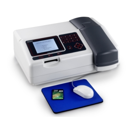
Jenway 6500/05
Introduction
Quick Reference
System Description
Optical Description
Electronic Description
Software Description
Diagnostics
Maintenance
Circuit Diagrams
Assembly Diagrams
Spare Parts List
Page 1 of 105
Advertisement
Chapters
Table of Contents


Need help?
Do you have a question about the 6500 and is the answer not in the manual?
Questions and answers