Sign In
Upload
Download
Table of Contents
Contents
Add to my manuals
Delete from my manuals
Share
URL of this page:
HTML Link:
Bookmark this page
Add
Manual will be automatically added to "My Manuals"
Print this page
×
Bookmark added
×
Added to my manuals
Manuals
Brands
jenway Manuals
Measuring Instruments
7300
Operating manual
jenway 7300 Operating Manual
Spectrophotometer
Hide thumbs
1
2
3
4
5
Table Of Contents
6
7
8
9
10
11
12
13
14
15
16
17
18
19
20
21
22
23
24
25
26
27
28
29
30
31
32
33
34
35
36
37
38
39
40
41
42
43
44
45
46
47
48
49
50
51
52
53
54
55
56
57
58
59
60
61
62
page
of
62
Go
/
62
Contents
Table of Contents
Troubleshooting
Bookmarks
Table of Contents
Safety
Table of Contents
Contents
SECTION 1 - Introduction
Instrument Description
Instrument Specification
SECTION 2 - Installation
Unpacking
Installation
Display
Controls
Rear Panel
Front Panel
SECTION 3 - Theory and Practice of Spectroscopy Measurements
Theory of Spectroscopy Measurement
Spectroscopy Measurement
Good Practice Guidelines
SECTION 4 - Instrument Setup
Navigating and Screen Setup
Time and Date
Instrument Settings Menu
Screen Contrast
Lamp Save
Section 5 - Photometrics
Mode Specific Parameters
Method Set up
Selecting a Wavelength
Calibration
Sample Measurment
Section 6 - Concentration
Mode Specific Parameters
Method Setup
Selecting a Wavelength
Settings
Selecting Concentration Units
Changing the Resolution
Using a Standard
Using a Factor
Calibration
Calibrating to a Standard
Calibrating to a Factor
Sample Measurement
Measuring a Sample after Calibrating to a Standard
Measuring a Sample after Calibrating to a Factor
Post Measurement Options
Changing Concentration Units
Changing the Concentration Factor
Changing the Calibration Standard Value
Section 7 - Printing and Autologging
Printing
Print Setup
Printing Results
Autologging
Setting the Number of Sample Repetitions
Selecting Result's Destination
Connecting to a Pc
SECTION 8 - Accessories and Spare Parts
Optional Accessories
Connecting the Accessories
Internal Printer
Passive Accessories
Water-Heated Cuvette Holder
Active Accessories
Automatic 8 Cell Turret
Peltier
Sipper Pump
Combined Sipper Peltier Pump
Using the Accessories
Automatic 8 Cell Turret
Peltier
Sipper Pump
Manual Sipper Pump Settings
Timed Sipper Pump Settings
Combined Sipper Peltier Pump
Spares
SECTION 9 - Maintenance and Service
Routine Maintenance
Lamp Replacement
Tungsten Halogen Lamp Replacement
Xenon Lamp Module Replacement
Service
SECTION 10 - Troubleshooting
Error Codes
Troubleshooting Guide
Technical Support
SECTION 11 - Declaration of Conformity
Advertisement
Quick Links
1
Instrument Description
2
Calibration
Download this manual
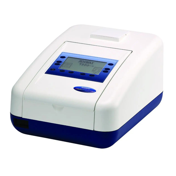
Model 7300 and 7305
Spectrophotometer
Operating Manual
730 005 REV D/08-14
Table of
Contents
Previous
Page
Next
Page
1
2
3
4
5
Advertisement
Table of Contents
Troubleshooting
SECTION 10 - Troubleshooting
53
TROUBLESHOOTING GUIDE
55
Need help?
Do you have a question about the 7300 and is the answer not in the manual?
Ask a question
Questions and answers
Related Manuals for jenway 7300
Measuring Instruments Jenway 7305 Operating Manual
Spectrophotometer (62 pages)
Measuring Instruments jenway Visible Range Spectrophotometer 6300 Operating Manual
Visible range spectrophotometer (17 pages)
Measuring Instruments jenway 6300 Service Manual
Spectrophotometers (68 pages)
Measuring Instruments Jenway 6405 Operating Manual
(52 pages)
Measuring Instruments Jenway Genova Nano Operating Manual
(31 pages)
Measuring Instruments Jenway PFP7 Instruction Manual
Flame photometer (48 pages)
Measuring Instruments jenway 3505 Operating Manual
Ph/mv/temperature meter (18 pages)
Measuring Instruments jenway 570 Instruction Manual
Ph, mv and temperature meter (20 pages)
Measuring Instruments jenway 6051 Instruction Manual
Colorimeter (16 pages)
Measuring Instruments jenway 6305 Operating Manual
Spectrophotometer (31 pages)
Measuring Instruments jenway 370 Operating Manual
Ph/mv meter (21 pages)
Measuring Instruments jenway 6850 Operating Manual
(56 pages)
Measuring Instruments Jenway 3345 Operating Manual
Ion meter (53 pages)
Measuring Instruments jenway PFP7 Operating Manual
Flame photometer (50 pages)
Measuring Instruments jenway 6500 Service Manual
(105 pages)
Measuring Instruments jenway 4520 Operating Manual
Conductivity/tds meter (40 pages)
This manual is also suitable for:
7305
Table of Contents
Print
Rename the bookmark
Delete bookmark?
Delete from my manuals?
Login
Sign In
OR
Sign in with Facebook
Sign in with Google
Upload manual
Upload from disk
Upload from URL


Need help?
Do you have a question about the 7300 and is the answer not in the manual?
Questions and answers