Table of Contents
Advertisement
Advertisement
Table of Contents

Related Manuals for jenway 6850


Summary of Contents for jenway 6850
- Page 1 6850 Spectrophotometer Operating Manual 685 030 REV B/06-14...
- Page 2 Safety Please read this information carefully prior to installing or using this equipment. 1. The unit described in this manual is designed to be operated only by trained personnel. Any adjustments, maintenance and repair must be carried out as defined in this manual, by a person qualified to be aware of the hazards involved.
- Page 3 Bitte lesen Sie diese Hinweise vor Installation oder Gebrauch dieser Ausrüstung sorgfältig durch. 1. Das in diesem Handbuch beschriebene Gerät darf nur von geschultem Personal bedient werden. Alle Anpassungen, Wartungsarbeiten und Reparaturen müssen entsprechend der Vorgaben in diesem Handbuch und von einer kompetenten Person, die mit den damit verbundenen Gefahren vertraut ist, durchgeführt werden.
- Page 4 4. È sempre necessario fare riferimento ai dati sulla salute e sulla sicurezza forniti con le sostanze chimiche utilizzate. Adottare le procedure di laboratorio generalmente accettate per la gestione delle sostanze chimiche. 5. Nel caso in cui si sospetti che la salute possa essere pregiudicata in qualsiasi modo, disattivare l'unità...
-
Page 5: Table Of Contents
Contents SECTION 1 – Introduction ..................8 INSTRUMENT DESCRIPTION..................... 8 INSTRUMENT SPECIFICATION..................8 SECTION 2 – Installation ................... 9 UNPACKING......................... 9 INSTALLATION ........................9 DISPLAY ..........................10 CONTROLS ........................11 REAR PANEL ........................13 FRONT VIEW ........................13 SECTION 3 – THEORY AND PRACTICE OF SPECTROSCOPY MEASUREMENTS .......................... - Page 6 SAMPLE MEASUREMENT ....................25 5.4.1 Photometric Measurements ....................25 5.4.2 Measuring a Sample after Entering a Concentration Factor ..........25 5.4.3 Measuring a Sample after Calibrating to a Standard ............26 SECTION 6 – QUANTITATION ................27 QUANTITATION MODE SCREEN ..................27 WAVELENGTH SELECTION .....................
- Page 7 STORING METHODS/RESULTS ..................43 RECALLING STORED RESULTS ..................44 SECTION 10 – MULTI-WAVELENGTH ..............45 10.1 MULTI-WAVELENGTH MODE OPTIONS ................. 45 10.2 WAVELENGTH SELECTION ..................... 45 10.3 SAMPLE MEASUREMENT ....................46 10.4 STORING METHODS/RESULTS ..................46 10.5 RECALLING STORED RESULTS ..................46 SECTION 11 –...
-
Page 8: Section 1 - Introduction
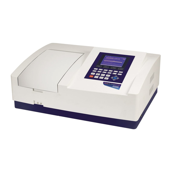
SECTION 1 – Introduction INSTRUMENT DESCRIPTION The 6850 is a variable bandwidth, double beam UV/visible spectrophotometer with an integrated user interface for local control. This instrument has highly stable optics and two detectors that measure the sample and reference solutions simultaneously to optimise the accuracy of the measurement. The 6850 has measurement modes for photometrics, concentration, multi-wavelength, spectrum scanning, quantitation, kinetics and DNA and Protein analysis. -
Page 9: Section 2 - Installation
INSTALLATION The 6850 is supplied ready to use. The working temperature and humidity range of the 6850 spectrophotometer is 15 – 35˚C, 15 – 70% relative humidity. The storage temperature and humidity range of the 6850 spectrophotometer is -10 – 50˚C, 15 – 70% relative humidity. -
Page 10: Display
The instrument will initially perform several power-on tests before displaying the warm up screen: Fig 2.2 – Instrument power-on tests complete The power-on tests comprise 1. Lamp test 2. Detector test 3. A to D converter test 4. Grating position check 5. -
Page 11: Controls
CONTROLS The keypad used for this model enables an easy and effective way of navigating the different measurement modes, entering numbers, saving and analysing results. The keypad is displayed below. Fig. 2.4 – Keypad Function Keys: Allows on-screen options to be selected …... - Page 12 ESC Key: Return to previous menu screen 100%T/0Abs Key: Zero / Blank instrument OPEN Key: Open results stored in internal memory SAVE Key: Save results to internal memory START/STOP Key: Start/Stop measurement GOTO Key: Set the instrument wavelength using the numeric keys.
-
Page 13: Rear Panel
REAR PANEL The image below shows the rear panel of the instrument: Fig. 2.5 – Rear Panel 1. Fan Cover Allows access to lamp when replacement is necessary 2. Power switch On/off switch for the unit 3. Power in socket Connection socket for power supply unit 4. -
Page 14: Section 3 - Theory And Practice Of Spectroscopy Measurements
SECTION 3 – THEORY AND PRACTICE OF SPECTROSCOPY MEASUREMENTS THEORY OF SPECTROSCOPY MEASUREMENT UV-visible spectroscopy is the measurement of the absorbance of light at a specific wavelength in a sample. This is used to identify the presence and concentration of molecular entities within the sample. -
Page 15: Nucleic Acid Determination
Conc (μg/ml) = (Abs@260nm x 49.1) – (Abs@230nm x 3.48) Referring to a blank value where no absorption should occur is commonly required. On the 6850 the default reference wavelength is 320nm and the user can include the measured absorbance value in all nucleic acid calculations. -
Page 16: Good Practice Guidelines
GOOD PRACTICE GUIDELINES 1. For optimum performance all spectrophotometers should be sited in a clean, dry, dust free atmosphere. When in use ambient temperature and light levels should remain as constant as possible. 2. If required adherence to Standard Operating Procedures (SOP) and Good Laboratory Practice (GLP) should be monitored with regular calibration checks and a suitable Quality Control (QC) programme. - Page 17 10. Cuvettes and sample holders must be filled to a minimum level which covers the light path. All Jenway spectrophotometers have a beam height of 15mm. 11. The instrument must be calibrated to zero absorbance/100% transmittance prior to taking readings.
-
Page 18: Section 4 - Instrument Setup
SECTION 4 – INSTRUMENT SETUP INSTRUMENT NAVIGATION To navigate around the spectrophotometer screen press the arrow keys on the main keypad and use the Enter key to select the highlighted option. Alternatively, some options and actions require the user to press the function and numeric keys on the instrument keypad. The Esc key can be used to return to the previous menu without saving any changes. -
Page 19: System Utility Menu
SYSTEM UTILITY MENU The system utility menu option allows the user to perform a variety of setup and service functions. 1. Wavelength calibration 2. Edit printer settings 3. Edit lamp settings 4. Edit time and date settings 5. Measure the instrument’s dark current 6. -
Page 20: Lamp Setup
4.3.3 Lamp Setup In the lamp setup menu the user can perform the following tasks. 1. Switch on/off the deuterium lamp 2. Reset the deuterium lamp usage timer 3. Switch on/off the tungsten lamp 4. Reset the tungsten lamp usage timer 5. -
Page 21: Set Date
4.3.4.2 Set Date Highlight the set date option and press the Enter key to confirm. This will allow the user to enter the current date in the format DD.MM.YY using the numerical keypad and the decimal point keys. Press the Enter key to confirm. Once complete the instrument will return to the Clock Setup menu. 4.3.4.3 Display Time / Date Highlight the display time or display date option and press the Enter key to confirm. -
Page 22: 4.3.10 Delete Entire Saved Files
4.3.10 Delete Entire Saved Files Highlight the delete entire saved files option and press the Enter key to confirm. A warning will be shown on screen and the user will need to confirm this command again by selecting the Yes option with the up and down arrow keys. -
Page 23: Section 5 - Photometrics
SECTION 5 – PHOTOMETRICS The photometrics measurement mode enables simple measurements of absorbance, % transmittance and concentration to be performed. In this measurement mode it is possible to calibrate against a standard of a known concentration or use a known factor. The sample is measured at one wavelength at one point in time. -
Page 24: Selecting The Unit Of Measurement
5.2.3 Selecting the Unit of Measurement The unit of measurement can be selected by pressing the function key below the Unit option. The required unit of measurement can then be selected from the available options of IU, mM/L, M/L, μg/mL, mg/mL, mg/L, mEq, ppb, ppm, % and other. Press the Enter key to confirm. 5.2.4 Entering a Concentration Factor The concentration of a sample can be determined by... -
Page 25: Calibrating To A Standard
5.3.2 Calibrating to a Standard A calibration standard can be used to determine the concentration factor. Insert the cuvette containing the blank solution into the reference position in the sample chamber and insert the cuvette containing the standard solution into the sample position. Close the instrument lid. -
Page 26: Measuring A Sample After Calibrating To A Standard
5.4.3 Measuring a Sample after Calibrating to a Standard Remove the cuvette containing the standard sample and place a cuvette containing the sample to be measured in the sample chamber. Close the instrument lid and the calculated concentration value will be shown on the screen. -
Page 27: Section 6 - Quantitation
SECTION 6 – QUANTITATION The quantitation measurement mode enables sample concentrations to be calculated using a standard curve. In this mode a number of standard solutions covering a range of known concentrations are measured. The absorbance or % transmittance of these solutions is plotted to create a standard curve. -
Page 28: Selecting The Unit Of Measurement
6.3.1 Selecting the Unit of Measurement The unit of measurement can be selected by pressing the function key below the Unit option. The required unit of measurement can then be selected from the available options of IU, mM/L, M/L, μg/mL, mg/mL, mg/L, mEq, ppb, ppm, % and other. Press the Enter key to confirm. 6.3.2 Quantitation Table Settings The quantitation table settings are accessed by... -
Page 29: Manually Enter Curve Constants
6.3.2.2 Manually Enter Curve Constants The user can manually enter the calibration curve constants by pressing the function key below the Params option. The user will be prompted to enter the constants that are required for the selected curve fit algorithm. -
Page 30: Creating A New Standard Curve
CREATING A NEW STANDARD CURVE The user must firstly edit the calibration table before attempting to create a new standard curve. Insert the cuvette containing the blank solution into the reference position in the sample chamber and insert the cuvette containing the first standard solution into the sample position. -
Page 31: Storing A Standard Curve
STORING A STANDARD CURVE A standard curve can be saved to the instrument’s internal memory to allow it to be recalled for future use. In the calibration table screen press the Save key on the instrument keypad. The instrument will ask the user to enter a filename (max. -
Page 32: Quantitation Measurements
6.7.1 Quantitation Measurements Ensure that a cuvette containing the blank solution is in the reference position in the sample chamber and insert the cuvette containing the sample solution into the sample position. Close the instrument lid and pres Start/Stop keypad. Once measurement is complete the determined result will be displayed in the quantitation mode screen. -
Page 33: Section 7 - Spectrum
SECTION 7 – SPECTRUM The spectrum measurement mode enables measurements of absorbance or % transmittance over a range of wavelengths to be performed. The absorbance or % transmittance at each wavelength is plotted graphically. Post measurement tools such as peaks and spectral points analysis can be performed. -
Page 34: Selecting The Measurement Mode
SELECTING THE MEASUREMENT MODE The measurement mode can be selected by pressing the function key below the Mode option. The required measurement mode can then be selected from the available options of Abs and %T using the up and down arrow keys. Press the Enter key to confirm. SAMPLE MEASUREMENTS Insert a cuvette containing the blank solution into the reference position in the sample chamber and insert... -
Page 35: Spectrum Search
SPECTRUM SEARCH The photometric values of the measured spectrum can be viewed by pressing the function key below the Search option. The user can press the up and down arrow keys to move between the peaks in the scan that are above the threshold peak height. -
Page 36: Recalling Stored Results
RECALLING STORED RESULTS A result file can be opened from the instrument’s internal memory. Press the Open key on the instrument keypad. The user can select from the list of stored files by pressing the up and down arrow keys. Once the required file has been located press the Enter key to confirm. -
Page 37: Section 8 - Kinetics
SECTION 8 – KINETICS The kinetics measurement mode enables the absorbance or % transmittance of an active molecule to be measured over a period of time; for example enzyme analysis of horseradish peroxidase. The absorbance or % transmittance is measured at regular time intervals at a set wavelength over a period of time. -
Page 38: Selecting The Measurement Mode
8.3.1 Selecting the Measurement Mode The measurement mode can be selected by pressing the function key below the Mode option. The required measurement mode can then be selected from the available options of Abs and %T using the up and down arrow keys. Press the Enter key to confirm. SAMPLE MEASUREMENTS Insert a cuvette containing the blank solution into the reference position in the sample chamber and insert... -
Page 39: Calculating I/U Concentration
CALCULATING I/U CONCENTRATION The instrument software allows the user to calculate the concentration of a substance from the difference between the photometric values at two time points in the displayed kinetics scan. To enter the calculation parameters press the function key below the Process option and enter a Start Time, an End Time and a Factor, pressing the Enter key to confirm each value. -
Page 40: Storing Results
STORING RESULTS A result file can be saved to the instrument’s internal memory. Press the Save key on the instrument keypad. The instrument will ask the user to enter a filename (max. 8 characters) using the alpha-numeric keypad. The user can select the indicated letters, numbers and symbols by repeatedly pressing the key until the required value is displayed, after a short period the next character can... -
Page 41: Section 9 - Dna/Protein
SECTION 9 – DNA/PROTEIN The DNA/Protein measurement mode allows the user to measure multi-wavelength absorbance ratios, such as 260nm/280nm and 260nm/230nm, which are commonly used to estimate a protein or nucleic acid sample’s purity. The mode also includes calculations that can be used to estimate the concentration of the protein or nucleic acid sample. -
Page 42: Wavelength Selection
Absorbance Difference 2 Purity Ratio = Abs@260nm / Abs@230nm RNA Conc (μg/ml) = (Abs@ x 49.1) – (Abs@ x 3.48) Protein Conc (μg/ml) = (Abs@230 x 183) – (Abs@260 x 75.8) The option to include the third wavelength as a reference is given after the measurement mode is selected. -
Page 43: Reset Mode Settings
RESET MODE SETTINGS The DNA/Protein mode settings can be reset to their default values by pressing the function key below the Default option. DNA/PROTEIN MEASUREMENTS Ensure that a cuvette containing the blank solution is in the reference position in the sample chamber and insert the cuvette containing the sample solution into the sample position. -
Page 44: Recalling Stored Results
RECALLING STORED RESULTS method/result file opened from instrument’s internal memory. In the DNA/Protein mode screen press the Open key on the instrument keypad. The user can select from the list of stored files by pressing the up and down arrow keys. Once the required file has been located press the Enter key to confirm. -
Page 45: Section 10 - Multi-Wavelength
SECTION 10 – MULTI-WAVELENGTH The multi-wavelength measurement mode allows the user to measure a sample’s photometric absorbance or %transmittance at up to 10 wavelengths. Following sample measurement, the photometric readings are displayed on the multi-wavelength mode screen. 10.1 MULTI-WAVELENGTH MODE OPTIONS The multi-wavelength measurement mode enables measurement parameters to be changed. -
Page 46: Sample Measurement
10.3 SAMPLE MEASUREMENT Insert a cuvette containing the sample to be analysed into the sample chamber and press the key below the sample measurement icon. The instrument will take a reading at each of the specified wavelengths the operating menu screen will then display the result of the selected measurement calculation and the photometric readings for each of the measured wavelengths. -
Page 47: Section 11 - Saving/Recalling Results Using A Usb Memory Stick
SECTION 11 – SAVING/RECALLING RESULTS USING A USB MEMORY STICK There is a USB port on the side of the instrument for data storage. The instrument only recognises a USB memory stick being inserted or removed when it is operating in the home screen. A USB icon appears at the top of the home screen (circled in red). -
Page 48: Section 12 - Accessories And Spare Parts
SECTION 12 – ACCESSORIES AND SPARE PARTS 11.1 OPTIONAL ACCESSORIES Part Code Description of Accessory 685 204 10 x 10mm path length cuvette holder 685 131 Water heated 10 x 10mm single cuvette holder 685 005 10 to 100mm adjustable path length cuvette holder 685 304 Micro-cuvette holder 685 401... -
Page 49: 11.2.2 Active Accessories
11.2.2 Active Accessories 11.2.2.1 8 Position Automatic Cell Changer Unscrew the two fixing screws to undo the passive accessory. Lift passive accessory. Fixing screws On the underside of the 8 cell accessory, locate accessories power supply communication connector. Accessory connector Take the 8 cell accessory and align the accessories connector... -
Page 50: Using The 8 Positon Automatic Cell Changer
Place the accessory in the correct orientation and re-tighten the two fixing screws to fix the 8 cell accessory in place. Fixing screws 11.3 USING THE 8 POSITON AUTOMATIC CELL CHANGER When the automatic 8 cell turret is installed the current cell position is indicated below the lamp status icons in the top right hand corner of the screen. -
Page 51: Spares
11.4 SPARES Part Code Description of Spare Part 685 020 Tungsten lamp 685 021 Deuterium lamp... -
Page 52: Section 12 - Maintenance And Setvice
SECTION 12 – MAINTENANCE AND SETVICE 12.1 ROUTINE MAINTENANCE Ensure the external surfaces of the unit are clean and free from dust. The sample area should always be kept clean and any accidental spillage should be wiped away immediately. To give added protection when not in use, the unit should be disconnected from the mains supply and covered with the optional dust cover. -
Page 53: 12.2.2 Deuterium Lamp Replacement
3. Whilst wearing cotton gloves remove the defective tungsten lamp and replace with a Tungsten Lamp new one. Entrance Window 4. Switch on the power and move the Switch Mirror down into the position shown in the picture opposite. Observing the entrance Switch Entrance Hole... -
Page 54: Service
Decontamination Certificate. This is available as a downloadable pdf file at www.jenway.com, or contact us and we will be happy to fax you a copy. Please clearly mark the package for the attention of the Service Department and post to the following address:... -
Page 55: Section 13 - Troubleshooting
13.2 TECHNICAL SUPPORT Jenway have a dedicated Technical Support team made up of experienced scientists who are on hand to help with any applications advice and questions you may have about our products and how to use them. If you require any technical or application assistance please contact the team at: E-mail: jenwayhelp@bibby-scientific.com. -
Page 56: Section 14 - Declaration Of Conformity
SECTION 14 – DECLARATION OF CONFORMITY...
Need help?
Do you have a question about the 6850 and is the answer not in the manual?
Questions and answers
What is the appropriate visible light source for?
The appropriate visible light source for the Jenway 6850 is the tungsten lamp.
This answer is automatically generated