Table of Contents
Advertisement
Advertisement
Table of Contents

Related Manuals for jenway PFP7


Summary of Contents for jenway PFP7
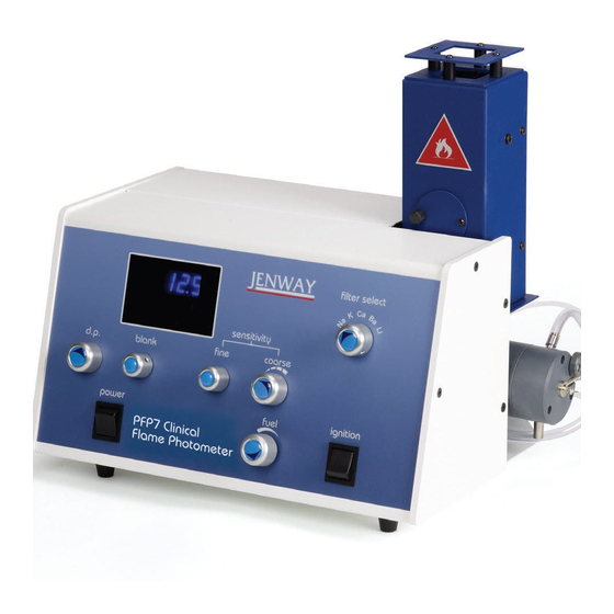
- Page 1 Flame Photometer Models PFP7 and PFP7/C Instruction Manual 500 795/REV E/03-17...
-
Page 2: Safety Information
English Safety Information Please read this information carefully prior to installing or using this equipment. 1. The unit described in this manual is designed be operated only by trained personnel. Any adjustments, maintenance and repair must be carried out as defined in this manual, by a person qualified to be aware of the hazards involved. - Page 3 substances the liberation of hazardous gases may require the use of a fume cupboard or other means of extraction. Be aware of biological contamination. Ensure sterilization of the capillary tube, waste, nebuliser and mixing chamber is performed after contamination. Ensure equipment is used on a clean, dry, non-combustible, solid work surface with at least 300mm suitable clearance all around and at least 1m clearance above the chimney.
- Page 4 Avoid installing the flame photometer in areas that are susceptible to drafts, but ensure that there is adequate ventilation to prevent any build-up of gas. Before using any cleaning or decontamination methods except those specified by the manufacturer, responsible bodies should check with the manufacturer that the proposed method will not damage the equipment.
- Page 5 Français Consignes de sécurité Veuillez lire attentivement ces informations avant d'installer ou d'utiliser cet équipement. 1. L'appareil décrit dans ce manuel est conçu pour n'être utilisé que par un du personnel qualifié. Tous les réglages et toutes les interventions d'entretien ou de réparation doivent être effectués tel que décrits dans ce manuel, par une personne habilitée et ayant été...
- Page 6 Pratiques de base pour une utilisation sûre Suivez toujours les bonnes pratiques de laboratoire lors de l'utilisation de cet appareil. Portez une attention particulière aux procédures de santé et de sécurité de votre entreprise et aux procédures réglementaires, ainsi qu'à toutes les lois applicables associées en vigueur dans votre région.
- Page 7 NE PAS déverser de substances sur l'appareil. En cas de déversement, déconnectez immédiatement l'appareil l'alimentation secteur. d'utilisation substances dangereuses, veuillez respecter les procédures d'utilisation de laboratoire standard. NE PAS placer l'appareil dans une position rendant difficile sa déconnexion de l'alimentation secteur. NE PAS déplacer et/ou transporter l'appareil en cours d'utilisation ou lorsqu'il est raccordé...
-
Page 8: Informazioni Sulla Sicurezza
Italiano Informazioni sulla sicurezza Si prega di leggere attentamente le seguenti istruzioni prima di installare o utilizzare questa apparecchiatura. 1. L'apparecchiatura descritta nel presente manuale è stata progettata per essere utilizzata esclusivamente da personale qualificato. Qualsiasi intervento a scopo di regolazione, manutenzione e riparazione deve essere eseguito secondo la modalità... - Page 9 Pratica di utilizzo sicuro generale Seguire sempre le buone pratiche di laboratorio quando si utilizza questa apparecchiatura. Accettare e implementare le procedure per la salute e la sicurezza vigenti, quelle stabilite dalla propria azienda e da qualsiasi normativa applicabile alla propria area di lavoro. Controllare le procedure di laboratorio per le sostanze utilizzate e assicurarsi che tutti i rischi potenziali (ad es.
- Page 10 rovesciare sostanze sull'apparecchiatura. caso rovesciamento, scollegare l'apparecchiatura dalla rete elettrica. Se si utilizzano sostanze pericolose, seguire le procedure operative standard di laboratorio. Non posizionare l'apparecchiatura in modo che sia difficile scollegarla dalla rete elettrica. Non spostare o trasportare l'apparecchiatura se in funzione o collegata alla rete elettrica.
- Page 11 Español Información de seguridad Lea atentamente esta información antes de instalar o usar el equipo. 1. La unidad descrita en este manual está diseñada para ser manejada solamente por personal cualificado. Cualquier ajuste, mantenimiento y reparación debe realizarse tal y como se define en este manual, por una persona cualificada y que sea consciente de los riesgos que implica.
- Page 12 Práctica operativa y de seguridad estándar Siga siempre las buenas prácticas de laboratorio cuando use este equipo. Tenga debidamente en cuenta los procedimientos legislativos de seguridad y de salud y seguridad de su compañía y toda la legislación asociada aplicable en las zonas de operación. Compruebe los procedimientos de laboratorio para las sustancias que están siendo usadas y asegúrese de que todos los riesgos (por ejemplo, explosión, implosión o liberación de gases tóxicos o...
- Page 13 No derrame sustancias sobre la unidad. Si se producen derrames, desconecte la unidad de la red eléctrica. Si usa sustancias peligrosas, cíñase a los procedimientos operativos de laboratorio estándar. No coloque el producto de modo que sea difícil desconectarlo de la red eléctrica.
- Page 14 Deutsch Sicherheitsinformationen Bitte lesen Sie diese Informationen sorgfältig durch, bevor Sie das Gerät installieren oder benutzen. 1. Das in diesem Handbuch beschriebene Gerät darf nur von geschultem Personal bedient werden. Einstellungen, Wartungs- und Reparaturarbeiten sind gemäß den Anweisungen in diesem Handbuch von einer qualifizierten Fachkraft durchzuführen, die über potenzielle Gefahren unterrichtet ist.
- Page 15 Allgemeine sichere Betriebspraxis Befolgen Sie bei der Verwendung des Geräts immer die gute Laborpraxis. Beachten Sicherheitsverfahren Ihres Unternehmens, gesetzlichen Gesundheits- Sicherheitsverfahren sowie sämtliche, damit verbundenen Rechtsvorschriften, die für Ihre Arbeitsgebiete gelten. Überprüfen Sie die Laborverfahren für die verwendeten Stoffe und stellen Sie sicher, dass alle...
- Page 16 Verschütten Sie keine Stoffe auf dem Gerät. Sollte dies trotzdem passieren, trennen Sie das Gerät von der Netzspannung. Halten Sie sich bei der Verwendung von gefährlichen Stoffen bitte an die Standardverfahren für den Laborbetrieb. Stellen Sie das Produkt nicht so auf, dass es schwierig ist, das Gerät von der Netzspannung zu trennen.
-
Page 17: Table Of Contents
SECTION 4 ..........................32 Operation .............................. 32 Front and rear panel controls ......................32 Operation – Flame Ignition and Optimisation ................... 34 Calibration: PFP7 ..........................36 Calibration: PFP7/C ..........................38 Shutdown ............................38 Operating precautions ........................39 SECTION 5 ..........................40 Accessories ............................ - Page 18 No electrical power ..........................45 Unable to set blank ..........................46 No reading on display ........................46 SECTION 8 ..........................46 Spares ..............................46 Minor Spares Kit (PFP7/MINKIT) ......................46 SECTION ..........................4 ........................4 500 795/Rev E/03-17 Page 18...
-
Page 19: Section 1
(Na), potassium (K) and lithium (Li). Additional filters for the determination of calcium (Ca) and barium (Ba) are supplied with the PFP7. Both versions are fitted with an automatic flame failure detection for user safety, making them ideal for use in clinical, industrial or educational applications. -
Page 20: Principles Of Operation
Principles of operation Flame photometry relies upon the fact that the compounds of the alkali and alkaline earth metals can be thermally dissociated in a flame and that some of the atoms produced will be further excited to a higher energy level. - Page 21 Flame Flame Filter Filter Photodetector Photodetector Readout Readout Amplifier Amplifier Lens Lens Burner Burner Gas inlet Gas inlet Mixing chamber Mixing chamber Nebuliser Nebuliser Waste Waste Drain Drain Air inlet Air inlet “U” tube “U” tube Figure 1.3.1: Schematic diagram showing the component parts of a flame photometer. The analysis of alkali and alkaline earth metals by flame photometry has two major advantages: Their atoms reach the excited state at a temperature lower than that at which most other elements are excited.
-
Page 22: Good Practice Guidelines
Good practice guidelines 1. It is most important that the nebuliser, mixing chamber and burner are kept clean by carrying out the correct shutdown procedure and by periodic maintenance. If high salt solutions are aspirated, correspondingly longer periods should be spent aspirating deionised water prior to shut down. 2. -
Page 23: Section 2
A supply of dry, clean and pulse-free air at a pressure at 15 - 30psi (approx. 1 - 2 kg/cm ) at 6 litres/minute is required. A suitable compressor and water separator are available from Jenway; refer to Section 2.5. 2.1.4 Drain The instrument will need to be sited near a drain or sink to enable disposal of waste liquid. -
Page 24: Unpacking
Unpacking Remove the instrument from the packaging and ensure the following items are present: Part Part Code 500 701 or 500 731 Model PFP7 Flame photometer 500 801 or 500 831 Model PFP7/C Flame photometer Auxiliary power plug 009 035... -
Page 25: Assembly
Mixing Chamber Assembly Place the instrument on a flat, stable bench and proceed as follows (see Figures 2.3.1 and 2.3.2 below): 1. Take the mixing chamber assembly and ensure that the fluted burner (1) is in place (remove the retaining tape). Place the mixing chamber and burner assembly inside of the flame photometer and line up the burner with the bottom of the chimney. - Page 26 Figure 2.3.2: Rear panel showing the drain trap, air and fuel inlets. Fluted burner Locking ring Nebuliser Nebuliser inlet Restrictor screw Fuel to mixing chamber inlet Mixing chamber to drain outlet End cap Drain trap clip 10) Drain trap to waste containter tubing 11) Mixing chamber to drain trap tubing 12) Compressed air to nebuliser tubing 13) Compressed air input connector...
-
Page 27: Installation
Installation WARNING The exhaust gases from the chimney are very hot. No obstruction should be placed above the instrument and the instrument should be located in a position that makes accidental contact with the chimney or its exhaust unlikely. The instrument needs to be operated in a well-ventilated room (although very strong draughts should be avoided). -
Page 28: Accessories
500 178 Propane regulator 500 179 Natural gas regulator 500 180 Water separator (small) 500 176 Water separator (large) 500 177 Dust cover 500 134 Cleaning solution (1 litre) 025 171 Minor spares kit PFP7/MINKIT 500 795/Rev E/03-17 Page 28... -
Page 29: Section 3
Section 3 Analysis Preparation Calibration standards A comprehensive range of aqueous calibration standards is available from Jenway. These must be diluted to a suitable concentration for aspiration into the flame (see Sections 3.3 and 4.3) Industrial Standards (500ml) Part Code... - Page 30 3.1.1 Sodium Accurately weigh 0.634g of dry “Analar” quality NaCl, dissolve in pure deionised water and wash into a 500ml volumetric flask. Fill to the mark with pure deionised water. To prepare the standard solution for use with the flame photometer, this stock solution should be diluted 1 in 50. Calculation: Atomic weight Na = 23.0 Molecular weight NaCl = 58.46...
-
Page 31: Sample Preparation
The sample must be in the form of an aqueous solution, with no solid matter present, to be suitable for direct introduction into the flame photometer. This is achieved by: Extracting the salts from solid samples using deionised water or suitable extractants e.g. saturated ·... -
Page 32: Section 4
Section 4 Operation Front and rear panel controls 4.1.1 Front panel controls Figure 4.1.1.1: Front panel A two-position rocker switch which controls the AC supply of the instrument. 1. Power Any accessories connected to the auxiliary POWER OUT sockets on the rear panel are also controlled by the front panel power switch. - Page 33 Course A five position control which will select the appropriate optical filter for the 7. Filter Select element being determined. NOTE: For the PFP7/C positions 3 and 4 will normally be blank 4.1.2 Rear panel controls Figure 4.1.2.1: Rear panel A two-position switch marked 230 and 115.
-
Page 34: Operation - Flame Ignition And Optimisation
2. FUSES to protect the instrument and any accessories connected to the power out sockets. FS2 is to protect the electronic circuitry in the PFP7. Both FS1 and FS2 should be of an anti-surge type. A three pin receptacle for the AC mains supply. - Page 35 6. Depress the ignition switch and hold down. Watch the FLM indicator in the display window. When this indicator is illuminated the flame is a light and the ignition switch can be released. If the FLM indicator does not light within approximately 20 seconds, release the switch and open the fuel valve one additional turn.
-
Page 36: Calibration: Pfp7
Calibration: PFP7 It is important to understand that the principles of flame photometry are such that, over certain concentration ranges, light emitted from the flame is directly proportional to the concentration of the species being aspirated. The graph below shows that the direct relationship between the flame emission and concentration is only true at relatively low concentrations. - Page 37 Initially this check should be carried out after every 10 samples. Experience and increased confidence in the PFP7 will enable you to best judge the frequency of this check. The decimal point (d.p.) switch can be set to illuminate the decimal point in any significant position.
-
Page 38: Calibration: Pfp7/C
Calibration: PFP7/C When using the PFP7/C, a calibration curve is not required as the display is calibrated in direct concentration units. Therefore only one top standard is required to enable this calibration to be performed. Installation and set-up procedures should be carried out as for the standard Model PFP7. -
Page 39: Operating Precautions
3. If the shutdown is longer term or if the laboratory is likely to be left unattended during the shutdown, then the fuel supply should be turned off at source; wait for the FLM indicator to extinguish and then turn off the power. This ensures that there is no gas left in the tubing to the unit. -
Page 40: Section 5
Accessories Water separator To avoid unstable readings it is essential that the air supply to the mixing chamber is clean and dry. Jenway recommends that a water separator be used with all flame photometers as when air is compressed, condensation occurs. The amount of condensation will depend on the humidity in the air, so in high humidity areas, water separators are essential. - Page 41 5.2.2 Installation The compressor should be positioned on a stable flat surface within 2 meters of the PFP7 or PFP7/C. Connection to the PFP7 or PFP7/C should be carried out as follows: 1. Ensure the power supply to the flame photometer is switched on.
-
Page 42: Maintenance
Maintenance General The design of the Model PFP7 & PFP7/C is such that maintenance requirements are minimal. To maintain good performance and prolong the life of the instrument it is important that the procedures defined in the manual are carried out regularly. The performance of the instrument depends upon an adequate supply of compressed air. -
Page 43: Six-Monthly Maintenance
2. With the flame alight aspirate a 1 in 100 diluted sample of cleaning solution for 30 minutes, followed by deionised water for a further 30 minutes. Six-monthly maintenance Burner cleaning. 10ml graduated measuring cylinder Equipment required: Stop watch Cleaning wire (I/500 194) Cleaning solution (025 171) Small, stiff brush 1. -
Page 44: Trouble Shooting
Section 7 Trouble shooting General This section is a step-by step guide that should allow an operator to take appropriate actions to clear simple faults. Any action not defined in this trouble shooting guide should only be undertaken by qualified personnel. - Page 45 Nebuliser blocked. Check the nebuliser performance as defined in Section 6.2, Weekly maintenance. Flame temperature not correctly set. Ensure the fuel valve is correctly set for the element being determined, refer to Section 4.2. Non-linear results Possible cause Solution Nebuliser blocked. Check the nebuliser performance as defined in Section 6.2, Weekly maintenance.
- Page 46 Select correct filter. Calibration standard incorrectly Re-make standard. made. Nebuliser completely blocked. Check the nebuliser performance as defined in Section 6.2, Weekly maintenance. Section 8 Spares Minor Spares Kit (PFP7/MINKIT) Description Part code Quantity Nebuliser 500019 Cleaning Wire (3x150mm) I/500194 Cleaning Solution...
-
Page 47: Eu Declaration Of Conformity
Year of CE Marking: 1996 Place of Issue Stone, Staffordshire, UK Date of Issue October 2009 Authorised Representative Carl Warren Title Technical Manager Signature Declaration of Conformity is also available to view online at www.jenway.com 500 795/Rev E/03-17 Page 47... - Page 48 Cole-Parmer Ltd. Beacon Road, Stone, Staffordshire, ST15 0SA, United Kingdom Tel: +44 (0)1785 812121 Email: cpinfo@coleparmer.com Web: www. .com...
Need help?
Do you have a question about the PFP7 and is the answer not in the manual?
Questions and answers