Sign In
Upload
Download
Table of Contents
Contents
Add to my manuals
Delete from my manuals
Share
URL of this page:
HTML Link:
Bookmark this page
Add
Manual will be automatically added to "My Manuals"
Print this page
×
Bookmark added
×
Added to my manuals
Manuals
Brands
jenway Manuals
Measuring Instruments
6405
Operating manual
jenway 6405 Operating Manual
Hide thumbs
1
Table Of Contents
2
3
4
5
6
7
8
9
10
11
12
13
14
15
16
17
18
19
20
21
22
23
24
25
26
27
28
29
30
31
32
33
34
35
36
37
38
39
40
41
42
43
44
45
46
47
48
49
50
51
52
page
of
52
Go
/
52
Contents
Table of Contents
Bookmarks
Table of Contents
Table of Contents
Contents
Safety
Introduction
Instrument Description
Instrument Specification
Installation
Unpacking
Controls
Inputs/Outputs
Operation
Operating Overview
Instrument Set-Up Menu
Photometrics
Spectrum Mode
Multi-Wavelength Mode
Kinetics Mode
Quantitation Mode
Good Practice Guidelines
Maintenance
General
Tungsten Halogen Lamp Replacement
Deuterium Lamp Replacement
Accessories
Spares
Interfacing
Serial Interface
Rs232
Recorder Output
Photometrics Mode
Spectrum Mode
Kinetics Mode
Quantitation Mode
Advertisement
Quick Links
1
Instrument Description
2
Instrument Specification
3
Operation
4
Operating Overview
5
Photometrics
6
Maintenance
7
Accessories
Download this manual
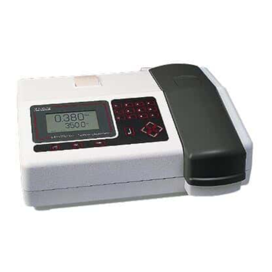
MODELS 6400/6405
SPECTROPHOTOMETERS
OPERATING MANUAL
640 050/REV B/11-99
Table of
Contents
Previous
Page
Next
Page
1
2
3
4
5
Advertisement
Table of Contents
Need help?
Do you have a question about the 6405 and is the answer not in the manual?
Ask a question
Questions and answers
Related Manuals for jenway 6405
Measuring Instruments jenway Visible Range Spectrophotometer 6300 Operating Manual
Visible range spectrophotometer (17 pages)
Measuring Instruments jenway 6300 Service Manual
Spectrophotometers (68 pages)
Measuring Instruments jenway 6850 Operating Manual
(56 pages)
Measuring Instruments Jenway 6400 Operating Manual
(52 pages)
Measuring Instruments jenway 6051 Instruction Manual
Colorimeter (16 pages)
Measuring Instruments jenway 6305 Operating Manual
Spectrophotometer (31 pages)
Measuring Instruments jenway 6500 Service Manual
(105 pages)
Measuring Instruments jenway 6505 Service Manual
(105 pages)
Measuring Instruments Jenway 7300 Operating Manual
Spectrophotometer (62 pages)
Measuring Instruments Jenway Genova Nano Operating Manual
(31 pages)
Measuring Instruments Jenway PFP7 Instruction Manual
Flame photometer (48 pages)
Measuring Instruments jenway 370 Operating Manual
Ph/mv meter (21 pages)
Measuring Instruments Jenway 3345 Operating Manual
Ion meter (53 pages)
Measuring Instruments jenway PFP7 Operating Manual
Flame photometer (50 pages)
Measuring Instruments jenway 4520 Operating Manual
Conductivity/tds meter (40 pages)
Measuring Instruments Jenway 7305 Operating Manual
Spectrophotometer (62 pages)
This manual is also suitable for:
6400
Table of Contents
Print
Rename the bookmark
Delete bookmark?
Delete from my manuals?
Login
Sign In
OR
Sign in with Facebook
Sign in with Google
Upload manual
Upload from disk
Upload from URL


Need help?
Do you have a question about the 6405 and is the answer not in the manual?
Questions and answers