Table of Contents
Advertisement
Quick Links
Advertisement
Table of Contents

Related Manuals for jenway 6051


Summary of Contents for jenway 6051
- Page 1 Colorimeter Model 6051 Instruction Manual Version 605 023/Rev F/07-17...
- Page 2 Safety Please read this information carefully prior to installing or using this equipment. 1. The unit described in this manual is designed to be operated only by trained personnel. Any adjustments, maintenance and repair must be carried out as defined in this manual, by a person qualified to be aware of the hazards involved. 2. It is essential that both operating and service personnel employ a safe system of work, in addition to the detailed instructions specified in this manual. 3. Other than for those items defined in the maintenance procedures herein there are no user serviceable items in this instrument. Removal of covers and attempted adjustment or service by unqualified personnel will invalidate the warranty and may incur additional charges for repair. 4. References should always be made to the Health and Safety data supplied with any chemicals used. Generally accepted laboratory procedures for safe handling of chemicals should be employed. Do not use hazardous or flammable substances in the instrument.
- Page 3 pour la manipulation en toute sécurité des produits chimiques. Ne pas utiliser de substances dangereuses ou inflammables sur l’appareil. 5. Si l’utilisateur suspecte qu’un problème quelconque puisse mettre en cause la sécurité, l’appareil doit être rendu inopérant en empêchant son utilisation. Communiquer la défaillance constatée au service de maintenance compétent. Le symbole d’alerte signale à l’utilisateur les informations importantes concernant l’utilisation de l’appareil. Lire et suivre les instructions fournies avec la plus grande attention. 7. ATTENTION. Si l’appareil n’est pas utilisé de manière adéquate, la protection de l’appareil pourrait être impactée. 8. Ne pas remplacer le cordon d’alimentation fourni par un cordon d’alimentation de dimension électrique non adapté. Bitte lesen Sie diese Hinweise vor Installation oder Gebrauch dieser Ausrüstung sorgfältig durch.
- Page 4 7. ACHTUNG: Wenn das Gerät nicht in der vorgegebenen Weise eingesetzt wird, können die Schutzfunktionen des Gerätes beeinträchtigt werden. 8. Abnehmbares Anschlusskabel nicht durch unangemessen bewertete Kabel austauschen. Leggere attentamente queste istruzioni prima di installare o utilizzare il dispositivo. 1. L’unità descritta nel presente manuale è stata realizzata per essere utilizzata solo da personale che ha ricevuto l’apposita formazione. Qualsiasi operazione di regolazione, manutenzione e riparazione deve essere effettuata sulla base di quanto indicato nel presente manuale da personale qualificato consapevole dei rischi connessi. 2. È fondamentale che il personale operativo e il personale addetto alla manutenzione utilizzino un sistema di lavoro sicuro, oltre a seguire le istruzioni specificate nel presente manuale. 3. Oltre a quelli indicati nelle procedure di manutenzione, all’interno di questo dispositivo non sono presenti altri elementi sui quali è possibile effettuare interventi. La rimozione delle protezioni e qualsiasi tentativo di regolazione o di manutenzione posto in essere da personale non qualificato invaliderà la garanzia. In questi casi, sarà necessario pagare un importo per le riparazioni effettuate. 4. È sempre necessario fare riferimento ai dati sulla salute e sulla sicurezza forniti con le sostanze chimiche utilizzate. Adottare le procedure di laboratorio generalmente accettate per la gestione delle sostanze chimiche. Non utilizzare sostanze pericolose o infiammabili sullo strumento. 5. Nel caso in cui si sospetti che la salute possa essere pregiudicata in qualsiasi modo, disattivare l’unità per renderla inutilizzabile. Qualsiasi condizione di errore deve essere immediatamente segnalata al responsabile per la manutenzione.
- Page 5 3. Cualquier elemento que no se encuentre entre los definidos en los procedimientos de mantenimiento aquí descritos no podrá utilizarse en este instrumento. La extracción de las tapas y los intentos de ajuste o reparación por parte de personal no cualificado invalidarán la garantía y pueden incurrir en cargos adicionales por reparación. 4. Siempre deberían consultarse los datos sobre Salud y Seguridad que se suministran con cualquier producto químico que se utilice. Es necesario llevar a cabo los procedimientos de laboratorio de aceptación generalizada para la manipulación segura de productos químicos. No utilice sustancias peligrosas o inflamables en el instrumento. 5. Si existe la sospecha de que las medidas protectoras de seguridad han quedado dañadas en cualquier modo, la unidad debe inutilizarse y protegerse contra toda operación que se intente llevar a cabo. El estado de fallo debe comunicarse inmediatamente a la autoridad de servicio de mantenimiento y reparación pertinente. El símbolo de advertencia avisa al usuario de información importante relacionada con el uso del instrumento. Lea atentamente y siga las instrucciones correspondientes. 7.
-
Page 6: Table Of Contents
CONTENTS SECTION 1 - INTRODUCTION ..................7 Instrument Description ..................7 1.2 I nstrument Specification ..................7 SECTION 2 - INSTALLATION ..................8 2.1 U npacking ..................8 Installation ..................8 Displays/Controls ..................9 Inputs/Outputs .................. 10 SECTION 3 - OPERATION .................. -
Page 7: Section 1 - Introduction
SECTION 1 - INTRODUCTION Instrument Description The Model 6051 is a general purpose laboratory colorimeter housed in a custom designed case. The visible spectrum is covered by eight gelatin filters incorporated within the unit. Optional interference filters are available to enable other visible wavelengths to be obtained, results are displayed in either %Transmittance, Absorbance or Concentration units via a 17mm L.C.D. readout. Samples may be presented to the 6051 in 10mm square cuvettes of standard or semi-micro volumes, test-tubes or Pour-in/Suck-out cells. An analogue output of 1mV per digit is available on the rear panel. -
Page 8: Section 2 - Installation
SECTION 2 - INSTALLATION Unpacking Remove the Model 6051 from the packaging and ensure the following items are present: 1. 6051 Colorimeter 2. Mains Cable 3. Pack 100 Disposable Plastic Cuvettes 4. Test Cuvette Installation Mains Supply The 6051 is designed to operate on 230 or 115V a.c. supplies (± 15%) 50/60Hz. The power consumption is 20W. The standard 2 metre mains lead supplied with the unit is fitted with an IEC type connector which can be plugged directly into the Power In socket on the rear panel. Fuse ratings: 230V = 250mA (Anti-surge) 115V = 500mA (Anti-surge) NOTE: The unit should be positioned within 1.5 metres of an earthed mains supply. -
Page 9: Displays/Controls
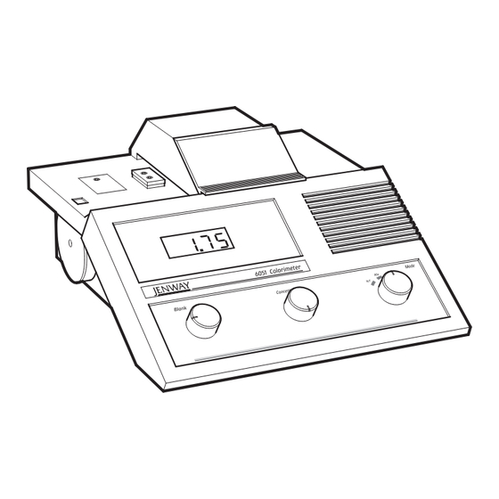
Displays/Controls Fig. 2.3.1 Front Panel Displays and Controls 1. Wavelength Select - Thumbwheel used to select the correct wavelength for the specific tests being performed. 2. Main display - 2½ Digit LCD. 3. Blank Control - This control is used when standardising the unit. Normal practice is to set the Abs or %T value with a cuvette of deionised water. The Blank control is then set to give the correct reading. 4. Concentration - This control is used when the mode switch is in the Conc 1 and 2 positions. These ranges are extensions of the Absorbance mode, allowing the reading obtained to be set to a value convenient to the standard concentration. 5. -
Page 10: Inputs/Outputs
Conc - (Concentration Ranges) - These ranges are extensions of the absorbance mode, allowing the reading to be set to a value convenient to the reference solution concentration. The reading may be increased or decreased by up to a factor of ten. 6. Sample Area - Samples may be presented in 10 x 10mm cuvettes of standard or semi-micro volumes or test tubes. 7. Sample Area Lid - The lid should be kept closed, when necessary to eliminate the possibility of erroneous results caused by the ingress of stray light. For many determinations, the lid may be left open. Inputs/Outputs Fig. 2.4.1 Rear Panel Layout 1. Zero - A preset control which should rarely require adjustment and is provided to offset photocell dark current. 2. Jack Socket - Connection socket for the external 12V d.c. supply. 3. 4mm Pin Sockets - An analogue voltage of 10mV per digit is available on these sockets. 4. -
Page 11: Section 3 - Operation
Initial Set-Up 1. Connect the unit to the mains supply and switch on. Select %T by use of the Function Switch. Allow 15 minutes warm-up period at this point to ensure the optical and electronic systems have sufficient time to stabilise. 2. Insert the test cuvette (black cuvette supplied with the unit) into the sample chamber. The wavelength reading is not critical at this point. The display should read zero. Adjustment to this reading can be made by use of the Dark Current Offset control located on the rear panel. If adjustment is required the blank and zero settings should be re-checked until they are both correct. 3. Remove the test cuvette from the sample chamber. 4. Fill a cuvette to within 1cm of the top with distilled or deionised water and place in the sample chamber. Close the sample chamber lid. Select the required wavelength or interference filter. Set the display to read 100 using the Blank Control. The reading should be stable. 5. Remove the cuvette from the unit. The 6051 is now ready for use. NOTE: During sample measurement the sample area lid should ideally be kept in the closed position to eliminate the possibility of erroneous results caused by the ingress of stray light. For many determinations, however, the lid may be left open without causing significant errors. Sample Measurement 1. Allow 15-minute Warm-Up prior to use refer to 3.1 Initial Set-Up. 2. Select the required filter position for maximum absorbance. If this is not known, the colour complimentary to that of the standard solution can be selected from the list given below. The chart may be read from left to right or right to left, i.e. a blue sample requires a yellow filter / a yellow sample requires a blue filter. Blue - Yellow Bluish/Green... -
Page 12: Good Practice Guidelines
6. The unit is now ready for operation in the Absorbance mode. 7. Operation in the %Transmittance mode can be performed by selecting %T using the Function switch. The unit will now read directly in %T and the blank sample should read 100 %T. 8. Operation in the Concentration mode can be performed by selecting either Conc 1 or 2 using the Function Switch. The standard value should be set to a convenient reading using the Concentration Control. The unit will now read directly in sample concentration. NOTE: To ensure optimum performance refer to Section 3.3 Good Practice Guidelines. 9. When using separate interference filters set the filter wheel to one of the “F” positions. Remove the blanking filter from the filter compartment and insert the interference filter to be used. The “F” positions have varying degrees of light attenuation to cater for the wide spread of transmission characteristics encountered with interference filters. The degree of attenuation varies from zero on position F1 through to a maximum on F4. In most normal circumstances position F1 will be most appropriate. If, however, lower than expected absorbance values are obtained, it is probable that the detector circuit is saturating and a range with more attenuation should be selected. The unit is now ready for use. -
Page 13: Section 4 - Maintenance, Servicing And Repair
SECTION 4 - MAINTENANCE, SERVICING AND REPAIR WARNING: Ensure the unit is disconnected from the mains electricity supply before attempting maintenance or servicing. Maintenance The 6051 has been designed to give optimum performance with minimum maintenance. The only maintenance required is to clean the external surfaces with a damp cloth and mild detergent and keep free from dust. To give added protection when not in use the unit should be disconnected from the mains supply and covered with the optional dust cover. For longer term storage or re-shipment, it is recommended that the unit be returned to the original packing case. Light Source Replacement The only routine maintenance which may be required is the replacement of the light source due to failure. Failure should be suspected if the reading remains at zero in %T mode or reads overrange in Abs or Conc modes. This can be confirmed by considering the cuvette chamber. -
Page 14: Servicing And Repair
Cole-Parmer Ltd. warrants this instrument to be free from defects in material and workmanship, when used under normal laboratory conditions, for a period of 3 years. In the event of a justified claim Cole-Parmer will replace any defective component or replace the unit free of charge. This warranty does NOT apply if damage is caused by fire, accident, misuse, neglect, incorrect adjustment or repair, damage caused by incorrect installation, adaptation, modification, fitting of non-approved parts or repair by unauthorised personnel. Cole-Parmer Ltd, Beacon Road, Stone, Staffordshire, ST15 0SA, United Kingdom Email: cpservice@coleparmer.com Tel: +44 (0)1785 810475 Web: www.jenway.com SECTION 6 - OPTIONAL ACCESSORIES Optional Extras The following list of items are available as optional accessories for use with the Model 6051: 060 084 Pack of 100 (10mm) Plastic Cuvettes (3ml) 060 087 Pack of 100 (1ml) Plastic Semi-micro Cuvettes (1ml) 035 027 10 x 10mm Glass Cell 035 056 10 x 20mm Glass Cell 035 029 10 x 40mm Glass Cell Interference Filters 606 018... -
Page 15: Eu Declaration Of Conformity
Signed for and on behalf of the above manufacturer Additional Information Year of CE Marking: 1996 Place of Issue Stone, Staffordshire, UK Date of Issue October 2009. Revised 14 July 2017 Authorised Representative Carl Warren Title Technical Manager Signature Declaration of Conformity is also available to view online at www.jenway.com... - Page 16 Cole-Parmer Ltd. Beacon Road, Stone, Staffordshire, ST15 0SA, United Kingdom Tel: +44 (0)1785 812121 Email: cpinfo@coleparmer.com Web: www.jenway.com...
Need help?
Do you have a question about the 6051 and is the answer not in the manual?
Questions and answers