Table of Contents
Advertisement
Quick Links
ECCO
HYBRID INVERTER
USER MANUAL
SUN-3K-SG04LP1-24-EU / SUN-3K-SG04LP1-EU
SUN-3.6K-SG04LP1-EU / SUN-5K-SG04LP1-EU
SUN-6K-SG04LP1-EU
Global Tech China Ltd, 3 Floor, Wai Yip Industrial Building.
171 Wai Yip Street, Kwun Tong, Kowloon, Hong Kong.
Tel: +852 2884 4318 Fax: +8522884 4816
www.sunsynk.com / sales@sunsynk.com
v.7 (12/09/22)
Advertisement
Table of Contents

Related Manuals for SunSynk ECCO SUN-3K-SG04LP1-24-EU


Summary of Contents for SunSynk ECCO SUN-3K-SG04LP1-24-EU
- Page 1 USER MANUAL SUN-3K-SG04LP1-24-EU / SUN-3K-SG04LP1-EU SUN-3.6K-SG04LP1-EU / SUN-5K-SG04LP1-EU SUN-6K-SG04LP1-EU Global Tech China Ltd, 3 Floor, Wai Yip Industrial Building. 171 Wai Yip Street, Kwun Tong, Kowloon, Hong Kong. Tel: +852 2884 4318 Fax: +8522884 4816 www.sunsynk.com / sales@sunsynk.com v.7 (12/09/22)
-
Page 2: Table Of Contents
Table of Contents SAFETY 1. 1.1. General Safety 1.2. Symbols 1.3. Safety Instructions 1.4. Disposal Remarks 2. PRODUCT INTRODUCTION 2.1. Product Size 2.2. Basic System Architecture 3. TECHNICAL SPECIFICATIONS 4. INSTALLATION 4.1. Parts List 4.2. Selecting the Mounting Area 4.3. System Diagram 4.4. Mounting the Inverter 4.5. Function Port Definition 4.6. Battery Connection 4.6.1. Recommended DC Battery Protection 4.7. Connecting a Lithium Battery 4.8. Battery Temperature Sensor Connection 4.9. Connecting the AC... - Page 3 5. OPERATION 5.1. Display 5.2. Switching ON/OFF 5.3. Home Page 5.4. Status Page 5.5. System Flow Page 5.6. Setup Page 5.7. Set Time (Clock) 5.8. Set Company Name / Beeper / Auto dim 5.9. Factory Reset and Lock Code 5.10. Battery Setup Page 5.11. Generator & Battery Page 5.12. Battery Discharge Page 5.13. Setting Up a Lithium Battery 5.14. Program Charge &...
- Page 4 APPENDIX A APPENDIX B APPENDIX C APPENDIX D APPENDIX E ECCO SG04LP1 | User Manual...
-
Page 5: Safety
1. SAFETY 1.1. General Safety This device should only be used in accordance with the instructions within this manual and in ƒ compliance with local, regional, and national laws and regulations. Only allow this device to be installed, operated, maintained, and repaired by other person(s) who have read and understood this manual. Ensure the manual is included with this device should it be passed to a third party. -
Page 6: Safety Instructions
1.3. Safety Instructions WARNING HIGH LIFE RISK DUE TO FIRE OR ELECTROCUTION. The Sunsynk Ecco Hybrid Inverter can only be installed by a qualified licensed electrical contractor. This is not a DIY product. Be sure to read this manual thoroughly before installation. -
Page 7: Product Introduction
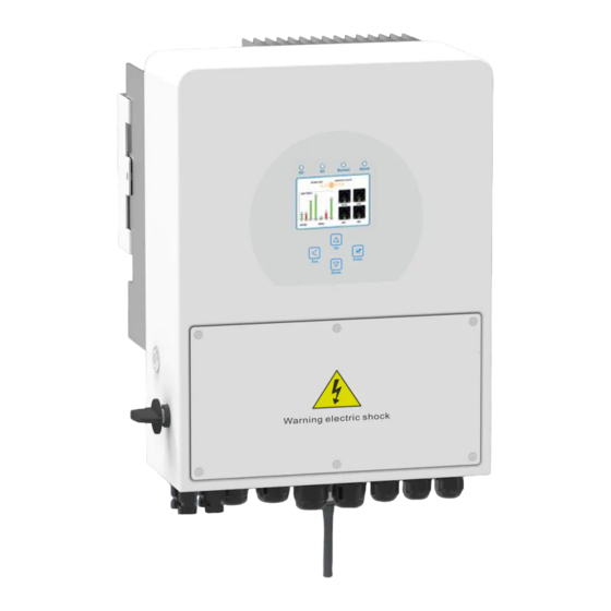
2. PRODUCT INTRODUCTION The Sunsynk Ecco Hybrid Inverter is a highly efficient power management tool that allows the user to hit those ‘parity’ targets by managing power-flow from multiple sources such as solar, mains power (grid) and generators, and then effectively storing and releasing power as and when utilities require. - Page 8 1. Inverter Indicators 7. Meter Port 13. Power On/Off Button 2. LCD Display 8. Function Port 14. DC Switch 3. Function Buttons 9. Parallel port 15. PV Input with Two MPPT 4. Battery Input Connectors 10. Generator input 16. Battery 5.
-
Page 9: Product Size
2.1. Product Size ECCO SG04LP1 | User Manual... -
Page 10: Basic System Architecture
2.2. Basic System Architecture The following illustration shows the basic application of this inverter. It also includes following devices to have a Complete running system. Generator or Utility ƒ PV modules ƒ Consult with your system integrator for other possible system architectures depending on your require- ments. -
Page 11: Technical Specifications
3. TECHNICAL SPECIFICATIONS SUN-3K-SG04LP1- SUN-3K-SG04LP1- SUN-3.6K- SUN-5K-SG04LP1- SUN-6K-SG04LP1- Model 24-EU SG04LP1-EU Battery Input Data Battery Type Lead-acid or Lithium-ion Battery Voltage Range 20~30V 40~60V Max. Charging Current 140A 120A 135A Max. Discharging Current 140A 120A 135A Charging Curve 3 Stages/Equalisation Number of Battery Input Charging Strategy for Li-Ion Self-Adaptation to BMS Battery... - Page 12 Certifications and Standards CEI 0-21, VDE-AR-N 4105, NRS 097, IEC 62116, IEC 61727, G99, G98, VDE Grid Regulation 0126-1-1, RD 1699, C10-11 Safety EMC / Standard IEC/EN 61000-6-1/2/3/4, IEC/EN 62109-1, IEC/EN 62109-2 General Data Operating Temperature -45~60°C, >45°C Derating Range Cooling Natural Cooling Noise...
-
Page 13: Installation
4. INSTALLATION 4.1. Parts List Check the equipment before installation. Please make sure nothing is damaged in the package. You should have received the items in the following package: ECCO SG04LP1 | User Manual... -
Page 14: Selecting The Mounting Area
4.2. Selecting the Mounting Area This Sunsynk Ecco Hybrid Inverter is designed for outdoor use (IP65). DO NOT install the inverter in the following areas: Areas with high salt content, such as the marine environment. It will deteriorate the metal parts and pos- ƒ... -
Page 15: System Diagram
4.3. System Diagram ALSO CONSIDER: Installing the indoor unit, outdoor unit, power supply cable, transmission cable, and remote control cable ƒ at least 1 metre away from any television or radio receiver. This will prevent TV reception interference or radio noise. This will prevent radio signal interference from external units that might interfere with the Wi-Fi or GSM monitoring. - Page 16 WARNING Risk of injury (Heavy Object). Remember that this inverter is heavy so users must be careful in handling the unit during installation especially when mounting or removing it from a wall. ECCO SG04LP1 | User Manual...
-
Page 17: Function Port Definition
4.5. Function Port Definition ECCO SG04LP1 | User Manual... -
Page 18: Battery Connection
4.6. Battery Connection For safe operation and compliance, a separate DC over-current protector or disconnect device is required between the battery and the inverter. In some applications, switching devices may not be required but over-current protectors are still required. Refer to the typical amperage in the table below for the required fuse or circuit breaker size. -
Page 19: Recommended Dc Battery Protection
CAUTION All wiring/connecting must be performed by qualified personnel. Before making the final DC con- nection or closing the DC Breaker/disconnection device, ensure the inverter unit is wired correctly. A reverse-polarity connection on the battery will damage the inverter. 4.6.1. Recommended DC Battery Protection ECCO SG04LP1 | User Manual... -
Page 20: Connecting A Lithium Battery
4.7. Connecting a Lithium Battery When connecting a Lithium battery, follow the connection steps below and check ‘Setting up a Lithium Bat- tery’ to connect with an inverter. 1. Connect the correct diameter of cable in accordance with the battery manufacture specifications along with recommended safety devices. - Page 21 ECCO SG04LP1 | User Manual...
-
Page 22: Connecting The Ac
4.9. Connecting the AC Before connecting to grid, please install a separate AC breaker between inverter and grid. Also, it is recom- mended that installs an AC breaker between backup load and inverter. This will ensure the inverter can be securely disconnected during maintenance and fully protected from over current. For the 3/3.6/5/6KW mod- el, the recommended AC breaker for backup load is 32A/40A. -
Page 23: Recommended Ac Surge Protector
4.9.1. Recommended AC Surge Protector ECCO SG04LP1 | User Manual... -
Page 24: Installing The Ct Coil
4.10. Installing the CT Coil The CT coil is one of the most important parts of the Sunsynk Ecco Hybrid Inverter. This device reduces the power of the inverter to prevent feeding power to the grid. This feature is also known as “Zero Export”. -
Page 25: Earth Connection (Mandatory)
Since the inverter is a true hybrid, then the bond must only be made when the inverter is operating in Island- ing Mode. To accommodate this, Sunsynk provides an AC output, which is connected to the A/T/S connec- tions whenever the inverter is running on Island Mode. Therefore, you can simply connect the coil of an AC relay to the ATS 240 connections. -
Page 26: Meter Connection
4.12. Meter Connection 4.12.1. System Connection for the CHNT Meter ECCO SG04LP1 | User Manual... -
Page 27: Wiring System For Inverter
4.13. Wiring System for Inverter ECCO SG04LP1 | User Manual... -
Page 28: Pv Connection
4.14. PV Connection Before connecting to PV panels, install a separate DC circuit breaker between the inverter and PV modules. In addition, we request users install PV junction boxes with surge protection to protect the system from a lightning strike. To avoid any malfunction, do not connect any PV modules with possible current leakage to the inverter. For example, grounded PV modules will cause current leakage to the inverter. -
Page 29: Pv Protection
4. Finally, insert the DC connector into the positive and negative input of the inverter. 4.15. PV Protection ECCO SG04LP1 | User Manual... -
Page 30: Single-Phase Parallel Connection Diagram
4.16. Single-Phase Parallel Connection Diagram ECCO SG04LP1 | User Manual... -
Page 31: Three-Phase Parallel Inverter
4.17. Three-Phase Parallel Inverter ECCO SG04LP1 | User Manual... -
Page 32: Operation
5. OPERATION 5.1. Display LED indicator Meaning Green LED solid light PV connection normal Green LED solid light Grid connection normal Normal Green LED solid light Inverter functioning normally Alarm Red LED solid light Fault Function Key Description To exit the previous mode Increase the value of a setting Down Decrease the value of a setting... -
Page 33: Home Page
5.3. Home Page Press the Esc button any page to access the home page: 1. Customer name 2. Access the settings menu page 3. Access solar history 4. Access system status page SOLAR/TURBINE AC load 5. Access system status page 6. Access grid history 7. -
Page 34: System Flow Page
What this page displays: Total solar power produced. Inverter voltage. ƒ ƒ MPPT 1 power/voltage/current. Inverter current. ƒ ƒ MPPT 2 power/voltage/current. Load power. ƒ ƒ Grid power. Load voltage. ƒ ƒ Grid frequency. Battery power charge/discharge. ƒ ƒ Grid voltage. Battery SOC. -
Page 35: Setup Page
What this page displays: The system flow. Battery status. ƒ ƒ MPPTs power. Power distribution to load or grid. ƒ ƒ 5.6. Setup Page To access Settings, click on the gear icon on the right top of the navigation menu. What this page displays: Serial number. -
Page 36: Set Time (Clock)
Access the Grid Setup Page (press the GRID icon). ƒ Access the real-time programmable timer/system mode (press the SYSTEM MODE icon). ƒ Access the advanced settings such as Paralleling and Wind Turbine (press the ADVANCE icon). ƒ Access the auxiliary load/smart load settings (press the AUX LOAD icon) ƒ... -
Page 37: Factory Reset And Lock Code
How to change the name: Change the letters in each box by moving the arrows up and down and then select OK. This will change the name on the home screen. SOLAR/TURBINE AC load BATTERY IN/OUT MPPT. GRID. Battery Grid How to set the auto dim: Set a number in the auto dim box to dim the LCD after a number of seconds. -
Page 38: Battery Setup Page
System self-check: Allows the user to conduct a system diagnosis. Test mode (only for engineers): For engineers to conduct tests. 5.10. Battery Setup Page To configure battery settings, click on the BATTERY icon and then on ‘Batt type’. What this page displays: Battery capacity in (Ah) –... -
Page 39: Generator & Battery Page
BMS setting. ƒ Active battery - This feature will help recover a battery that is 100% discharged by slowly changing from ƒ the solar array. Until the battery reaches a point where it can change normally. 5.11. Generator & Battery Page To configure battery charging settings, click on the BATTERY icon and then on ‘Batt Charge’. - Page 40 1Amp 12V. Below is a simple reference circuit of an auto-start system that can autostart generators on a boat. (Sunsynk will be releasing a new OS E406 ( Auto-Start ) for better generator control).
-
Page 41: Battery Discharge Page
5.12. Battery Discharge Page To configure inverter’s shutdown settings, click on the BATTERY icon and then on ‘Shut Down’. ECCO SG04LP1 | User Manual... - Page 42 Activating Shutdown causes the inverter to enter standby-mode. It does not entirely shut down the inverter. Total shutdown occurs at voltages below 19V. The voltage displayed on the Sunsynk Parity Inverter will vary depending on whether the inverter is charging or discharging the batteries.
-
Page 43: Setting Up A Lithium Battery
The batteries recommended for use with the Sunsynk systems are AGM Lead Acid or Lithium Battery Banks. (‘AGM’ means Absorbed Glass Matt construction that allows the electrolyte to be suspended new the plate’s active material. In theory, this enhances both the discharge and recharging efficiency. AGM batteries are very heavy as a result). - Page 44 PLEASE NOTE With some types of lithium battery, the BMS cannot be controlled by the Sunsynk inverter. In this case, treat the battery as a lead-acid type and set the charging and discharging protocol following the bat- tery manufacturer specification.
- Page 45 RS485 Inverter Brand Model Storage Notes or CAN Setup Inverter US2000B RS485 US3000 RS485 US2000C RS485 US3000C RS485 PYLON UP5000 RS485 US5000 RS485 Force L1 RS485 Force L2 RS485 HUBBLE AM-2 5.5KW SSIF2P15S48100C RS485 SACRED SUN FCIFP48100A RS485 Cut Line 3, 6, 8 ...
- Page 46 RS485 Inverter Brand Model Storage Notes or CAN Setup Inverter IPACK DOWELL C3.3/IPACK C6.5/IPACK C10 G2500-48V Giter G5040-48V CFE2400 CF Energy CFE5100 CFE5100S Batterich/ UP3686 Greenrich BYD Battery-Box LV Flex Lite RJ45 Pin 1: GND 48NPFC80 RS485 RJ45 Pin 2: RS485_A RJ45 Pin 3: RS485_B RJ45 Pins 4, 5, 6, 7, 8: No...
- Page 47 RS485 Inverter Brand Model Storage Notes or CAN Setup Inverter Shanghai GTEM-48V2500 Green RS485 Tech Co.,Ltd. Unipower UPI.FP4845 RS485 LD-100P210J RS485 B-LFP51.2V 100Ah Float voltage 54.5V B-FLP51.2V 125Ah Absorption V 55.00V B-LFP48-130E 51.2V Disable equalisation 0 130Ah Days B-LFP48-160E 51.2V Shutdown 20% 160Ah Low Batt 35%...
-
Page 48: Program Charge & Discharge Times
5.14. Program Charge & Discharge Times To set ‘Charge’ and ‘Discharge’ times, click on the ‘System Mode’ icon after clicking on the gear icon. What this page displays: A setting to prevent the inverter exporting power to the grid - ‘Zero Export’. ƒ... - Page 49 Concerning the detailed figures above: 1. Tick this box to do not export power back to the grid (the CT coil will detect power flowing back to the grid and will reduce the power of the inverter only to supply the local load). 2.
-
Page 50: Grid Supply Page
Example: The power produced is supplying the ‘Non-Essential Load’ while the inverter is set at a maximum power of 8kW (Max Sell Power). The inverter is connected to the grid, but no export is performed. The unit allows small amounts of power to flow from the Grid (100W Zero Export Power) to prevent any back-flow. In this example, the solar PV is prioritised to supply the Load first and then subsequently, charge the battery. -
Page 51: Connecting The Drm's
What this page displays: Grid frequency setting. ƒ Grid type (normally 230V three-phase). ƒ What you can do from this page: Set the Minimum Grid Input Voltage (‘Grid Vol Low’). ƒ Set the Maximum Grid Frequency (‘Grid Hz High’). ƒ Set the Minimum Grid Frequency (‘Grid Hz Low). -
Page 52: Advanced Settings For Paralleling Inverters
Set the Modbus SN for paralleling. ƒ The Sunsynk parity inverter can be wired standalone or where more power is required it can be connected in parallel either single or 3 phase configuration. The maximum number of inverters that can be paral- leled in a single phase utility grid is 16 and the maximum number that can be paralleled in a three phase utility grid is 15. - Page 53 For stability, all the batteries need to be connected in parallel. It is recommended a minimum cable size of 50mm diameter with fuse isolators to each inverter. Each invert will require a fuse isolator with surge protection and each group circuit will require an RCD. If the batteries as supplying power to the main load during the outage then a change over switch will also be required or a split load can be used.
- Page 54 If you need further help please refer to the Sunsynk website where you will find training videos and Fre- quently Asked Questions www.sunsynk.com. Firmware prior installation is important to be updated and all inverters in parallel or three phase system must be the same.
-
Page 55: Solar Power Generated
5.18. Solar Power Generated This page shows the daily, monthly, yearly, and total solar power produced. Access this page by clicking on the ‘Solar/Turbine’ icon on the Home Page. 5.19. Grid Power This page shows the Daily / Monthly / Yearly and total grid power export or consumed. Access this page by clicking on the ‘Solar/Turbine’... -
Page 56: Advanced Settings For Wind Turbines
5.20. Advanced Settings for Wind Turbines To configure wind turbine settings, click on the ADVANCE icon. What this page displays: If one or both of the MPPTs are connected to a wind turbine. ƒ What you can do from this page: Select the MPPT to be used as a turbine input. -
Page 57: Advanced Settings For Auxiliary Load
Most wind turbines are three-phase PM type. Therefore, either a wind turbine controller or a direct connec- tion to the MPPT via a simple protection circuit will be required. Dump Load or Diversion Load is an important part of an off-grid power system. When the battery ( Battery Bank ) is fully charged, and the water turbine / wind turbine / solar PV module is still generating, a dump load is a useful device to send spare electricity to. -
Page 58: Advanced Settings For Peak Shaving
Aux Load off Battery % or Battery level when the Aux load switches off Voltage Aux Load on Battery % or Battery level when the Aux load switches on. Voltage Solar Power Power limiter to the maximum power allowed to the Aux load. Gen Input Tick this box if using a Generator. -
Page 59: Fault Codes
Solutions Inverter work mode changed Working Mode 1.Reset the inverter. Change 2.Seek help from Sunsynk. AC Slide over current fault. AC over current 1.Check if the backup load power is within the range of the inverter. fault or hardware 2.Restart, and check if it is normal. - Page 60 Error Code Description Solutions PV isolation resistance is too low 1.Check if the connection of PV panels and inverter are firmly con- DC insulation im- nected. pedance failure 2.Check if the earth bond cable on inverters is connected to the ground.
- Page 61 Before leaving the factory, all inverters undergo rigorous testing to ensure the inverter can operate reliably as presented in Chapter 3 ‘Technical Specifications’. If you need further help please refer to the Sunsynk website where you will find training videos and frequent- ly asked questions www.sunsynk.com.
-
Page 62: Operating Modes
6. OPERATING MODES 6.1. Mode I: Basic 6.2. Mode II: With Generator ECCO SG04LP1 | User Manual... -
Page 63: Mode Iii: With Smart Load
6.3. Mode III: With Smart Load 6.4. Mode IV: AC Couple ECCO SG04LP1 | User Manual... - Page 64 ECCO SG04LP1 | User Manual...
-
Page 65: Commissioning
7. COMMISSIONING 7.1. Start-Up / Shutdown Procedure The inverter must be installed by a qualified / licensed electrical engineer in accordance to the countries wiring regulations. Before switching on, the installation engineer must have completed the Earth Bond, RCD and earth leakage tests, checked that the solar panel Voc voltage does not exceed 480V and checked the battery voltage. -
Page 66: Information For Commissioning The Inverter
7.2. Information for Commissioning the Inverter After you have successfully powered up the inverter, it must be programmed and set up as per the program- ming feature above. Check each bond on the Check the VOC does not Ensure both MPPTs are solar panels exceed 480V balanced... -
Page 67: Gdfi Fault
7.3. GDFI Fault Before the inverter connects to the Grid, it will detect the impedance (effective resistance) of the solar PV + to Ground, and the impedance of the solar PV - to ground. If any of the impedance values are less than 33kΩ, the inverter will not connect to the Grid and will report an error F24 on its LCD. - Page 68 2. Be of the type specified in the inverter manufacturer’s instructions or as labelled on the inverter. We recommend the use of an RCD on all circuits and sub-circuits connected to the Sunsynk Inverter. Below is the specifications for a Residual Current Breaker with Overcurrent Protection (RCBO)
- Page 69 Instantaneous APPENDIX E The Sunsynk inverter can be connected to the internet, but you need to add a data logger to do this. The inverter is compatible with Solar Man data-loggers, which you can obtain from us with your distributor 1.
- Page 70 wered by...
Need help?
Do you have a question about the ECCO SUN-3K-SG04LP1-24-EU and is the answer not in the manual?
Questions and answers