Table of Contents
Advertisement
Quick Links
ECCO HYBRID INVERTER
USER MANUAL
SUN-3K-SG04LP1-24-EU / SUN-3K-SG04LP1-EU
SUN-3.6K-SG04LP1-EU / SUN-5K-SG04LP1-EU
SUN-6K-SG04LP1-EU
Global Tech China Ltd, 3 Floor, Wai Yip Industrial Building.
171 Wai Yip Street, Kwun Tong, Kowloon, Hong Kong.
Tel: +852 2884 4318 Fax: +8522884 4816
www.sunsynk.com / sales@globaltech-china.com
v.3 (06/13/22)
Advertisement
Table of Contents

Related Manuals for SunSynk ECCO SUN-3K-SG04LP1-24-EU


Summary of Contents for SunSynk ECCO SUN-3K-SG04LP1-24-EU
- Page 1 USER MANUAL SUN-3K-SG04LP1-24-EU / SUN-3K-SG04LP1-EU SUN-3.6K-SG04LP1-EU / SUN-5K-SG04LP1-EU SUN-6K-SG04LP1-EU Global Tech China Ltd, 3 Floor, Wai Yip Industrial Building. 171 Wai Yip Street, Kwun Tong, Kowloon, Hong Kong. Tel: +852 2884 4318 Fax: +8522884 4816 www.sunsynk.com / sales@globaltech-china.com v.3 (06/13/22)
-
Page 2: Table Of Contents
Table of Contents 1. SAFETY ......................4 1.1. General Safety ......................4 1.2. Symbols ........................4 1.3. Safety Instructions .....................5 1.4. Disposal Remarks ......................5 2. PRODUCT INTRODUCTION ................6 2.1. Product Size .......................8 2.2. Basic System Architecture ..................9 3. TECHNICAL SPECIFICATIONS ..............10 4. INSTALLATION ...................11 4.1. - Page 3 5.5. System Flow Page ....................33 5.6. Setup Page .......................34 5.7. Set Time (Clock) .......................34 5.8. Set Company Name / Beeper / Auto dim ..............35 5.9. Factory Reset and Lock Code ................36 5.10. Battery Setup Page ....................37 5.11. Generator & Battery Page ..................38 5.12.
-
Page 4: Safety
1. SAFETY 1.1. General Safety ƒ This device should only be used in accordance o instructions within this manual and in compliance with local, regional and national laws and regulations. Only allow this device to be installed, operated, maintained, repaired by other persons who have also read and un- derstood this manual. -
Page 5: Safety Instructions
1.3. Safety Instructions HIGH LIFE RISK DUE TO FIRE OR ELECTROCUTION. The Sunsynk Single-Phase Hybrid Inverter can only be installed by a qualified li- censed electrical contractor. This is not a DIY product. ƒ Be sure to read this manual thoroughly before installation. -
Page 6: Product Introduction
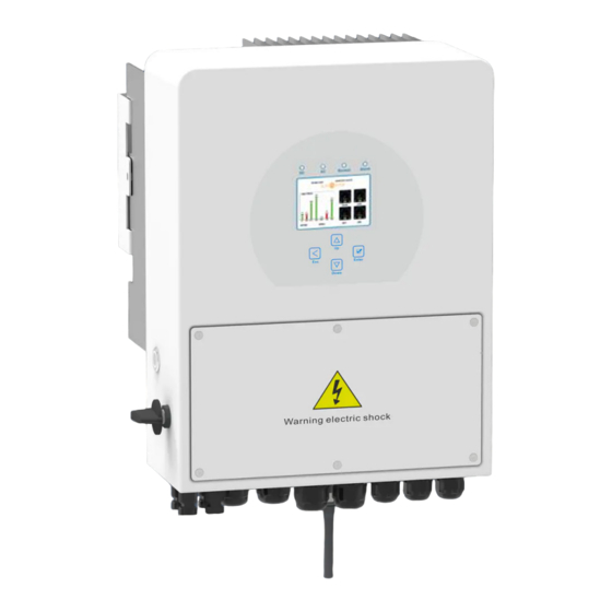
2. PRODUCT INTRODUCTION The Sunsynk Single-Phase Hybrid Inverter is a highly efficient power management tool that allows the user to hit those ‘parity’ targets by managing power-flow from multiple sources such as solar, mains power (grid) and generators, and then effectively storing and releasing power as and when utilities require. - Page 7 1. Inverter Indicators 7. Meter Port 13. Power On/Off Button 2. LCD Display 8. Functon Port 14. DC Switch 3. Function Buttons 9. Parallel port 15. PV Input with Two MPPT 4. Battery Input Connectors 10. Generator input 16. Battery 5.
-
Page 8: Product Size
2.1. Product Size Page | 8 Ecco Hybrid Inverter | User Manual... -
Page 9: Basic System Architecture
2.2. Basic System Architecture The following illustraton shows basic applicaton of this inverter. It also includes following devices to have a Complete running system. ƒ Generator or Utlity ƒ PV modules Consult with your system integrator for other possible system architectures depending on your requirements. -
Page 10: Technical Specifications
3. TECHNICAL SPECIFICATIONS SUN-3K- SUN-3K- SUN-3.6K- SUN-5K- SUN-6K- Model SG04LP1-24-EU SG04LP1-EU SG04LP1-EU SG04LP1-EU SG04LP1-EU Battery Input Data Battery Type Lead-acid or Lithium-ion Battery Voltage Range 20~30V 40~60V Max. Charging Current 140A 120A 135A Max. Discharging Current 140A 120A 135A Charging Curve 3 Stages/Equalisation Number of Battery Input Charging Strategy for Li-Ion Battery... -
Page 11: Installation
4. INSTALLATION 4.1. Parts List Check the equipment before installation. Please make sure nothing is damaged in the package. You should have received the items in the following package: Ecco Hybrid Inverter | User Manual Page | 11... -
Page 12: Selecting The Mounting Area
4.2. Selecting the Mounting Area This Sunsynk Ecco Hybrid Inverter is designed for outdoor use (IP65). DO NOT install the inverter in the following areas: ƒ Areas with high salt content, such as the marine environment. It will deteriorate the metal parts and possibly lead to water/dampness penetrating the unit. -
Page 13: System Diagram
4.3. System Diagram ALSO CONSIDER: ƒ Installing the indoor unit, outdoor unit, power supply cable, transmission cable, and remote control cable at least 1 metre away from any television or radio receiver. This will prevent TV reception interference or radio noise. This will prevent radio signal interference from external units that might interfere with the Wi-Fi or GSM monitoring. - Page 14 Risk of injury (Heavy Object) Remember that this inverter is heavy so users must be careful in handling the unit during installation especially when mounting or removing from a wall. Page | 14 Ecco Hybrid Inverter | User Manual...
-
Page 15: Function Port Definition
4.5. Function Port Definition Ecco Hybrid Inverter | User Manual Page | 15... -
Page 16: Battery Connection
4.6. Battery Connection For safe operation and compliance, a separate DC over-current protector or disconnect device is required between the battery and the inverter. In some applications, switching devices may not be required but over-current protectors are still required. Refer to the typical amperage in the table below for the required fuse or circuit breaker size. -
Page 17: Recommended Dc Battery Protection
All wiring/connecting must be performed by qualified personnel. Before making the final DC connection or closing the DC Breaker/disconnection device, ensure the inverter unit is wired correctly. A reverse-polarity connection on the battery will damage the inverter. 4.6.1. Recommended DC Battery Protection Ecco Hybrid Inverter | User Manual Page | 17... -
Page 18: Connecting A Lithium Battery
4.7. Connecting a Lithium Battery When connecting a Lithium battery, follow the connection steps below and check ‘Setting up a Lithium Battery’ to connect with an inverter. 1. Connect the correct diameter of cable in accordance with the battery manufacture specifi- cations along with recommended safety devices. - Page 19 Ecco Hybrid Inverter | User Manual Page | 19...
-
Page 20: Connecting The Ac
4.9. Connecting the AC Before connecting to grid, please install a separate AC breaker between inverter and grid. Also, it is recommended that installs an AC breaker between backup load and inverter.This will ensure the inverter can be securely disconnected during maintenance and fully protected from over cur- rent. -
Page 21: Recommended Ac Surge Protector
4.9.1. Recommended AC Surge Protector Ecco Hybrid Inverter | User Manual Page | 21... -
Page 22: Installing The Ct Coil
4.10. Installing the CT Coil The CT coil is one of the most important parts of the Sunsynk Ecco Hybrid Inverter. This device reduces the power of the inverter to prevent feeding power to the grid. This feature is also known as “Zero Export”. -
Page 23: Earth Connection (Mandatory)
Since the inverter is a true hybrid then the bond must only be made when the inverter is oper- ating in Islanding Mode. To accommodate this, Sunsynk provides an AC output, which is con- nected to the A/T/S connections whenever the inverter is running on Island Mode. Therefore, you can simply connect the coil of an AC relay to the ATS 240 connections. -
Page 24: Meter Connection
4.12. Meter Connection 4.12.1. System Connection for the CHNT Meter 4.12.2. System Connection for the Eastron Meter Page | 24 Ecco Hybrid Inverter | User Manual... -
Page 25: Wiring System For Inverter
4.13. Wiring System for Inverter Ecco Hybrid Inverter | User Manual Page | 25... -
Page 26: Pv Connection
4.14. PV Connection Before connecting to PV panels, install a separate DC circuit breaker between the inverter and PV modules. In addition, we request users install PV junction box with surge protection to pro- tect the system from lightning strike. To avoid any malfunction, do not connect any PV modules with possible current leakage to the inverter. -
Page 27: Pv Protection
3. Insert the contact pin into the connector housing until it locks into place. Then screw the cap nut onto the connector housing. Torque to 2.5-3 N.m 4. Finally, insert the DC connector into the positive and negative input of the inverter. 4.14.3. -
Page 28: Single-Phase Parallel Connection Diagram
4.15. Single-Phase Parallel Connection Diagram Page | 28 Ecco Hybrid Inverter | User Manual... -
Page 29: Three-Phase Parallel Inverter
4.16. Three-Phase Parallel Inverter Ecco Hybrid Inverter | User Manual Page | 29... -
Page 30: Operation
5. OPERATION 5.1. Display LED indicator Meaning Green LED solid light PV connection normal Green LED solid light Grid connection normal Normal Green LED solid light Inverter functioning normally Alarm Red LED solid light Fault Function Key Description To exit the previous mode Increase the value of a setting Down Decrease the value of a setting... -
Page 31: Switching On/Off
5.2. Switching ON/OFF Once the inverter has been correctly installed and the batteries have been connected, press the ON/OFF button (located on the left side of the case) to activate the system. When the system is connected without a battery but connected with either PV or grid and the ON/OFF button is switched off, the LCD will still illuminate (display will show off). -
Page 32: Status Page
5.4. Status Page To access the Status page, click on the BATTERY or AC LOAD dial on the Home page. What this page displays: ƒ Total solar power produced. ƒ MPPT 1 power/voltage/current. ƒ MPPT 2 power/voltage/current. ƒ Grid power. ƒ... -
Page 33: System Flow Page
5.5. System Flow Page Access by clicking on the bar chart on the Home Page. To better understand the functioning of your system, take a look at the figure bellow: 1. The PV modules charge the batteries. 2. When the batteries reach a specific level (programmable) the battery power is fed into the inverter. -
Page 34: Setup Page
5.6. Setup Page To access the Settings, click on the gear icon on the right top of the navigation menu. What this page displays: ƒ Serial number. ƒ Software version. ƒ Time, Date, and MCU. What you can do from this page: ƒ... -
Page 35: Set Company Name / Beeper / Auto Dim
5.8. Set Company Name / Beeper / Auto dim To set company name click on the BASIC icon and then on ‘Display’. What this page displays: ƒ Beeper status (ON/OFF). ƒ Installers names. What you can do from this page: ƒ... -
Page 36: Factory Reset And Lock Code
5.9. Factory Reset and Lock Code To access the Settings, click on the gear icon on the right top of the navigation menu. What this page displays: ƒ Reset status. ƒ Whehter the ‘lock code’ is used or not. What you can do from this page: ƒ... -
Page 37: Battery Setup Page
5.10. Battery Setup Page To configure battery settings, click on the BATTERY icon and then on ‘Batt type’. What this page displays: ƒ Battery capacity in (Ah) – For non-BMS-batteries the range allowed is 0-2000Ah, while for lithium-ion the inverter will user the capacity value of the BMS. ƒ... -
Page 38: Generator & Battery Page
5.11. Generator & Battery Page To configure battery charging settings, click on the BATTERY icon and then on ‘Batt Charge’. What this page displays: ƒ Generator start voltage/SOC %. ƒ Grid power start voltage/SOC %. ƒ Float V is the voltage at which a battery is maintained after being fully charged. ƒ... - Page 39 The current on thee contacts is limited to approximately, 1Amp 12V. Below is a simple reference circuit of an auto start system that can autostart generators on a boat. (Sunsynk will be releasing a new OS E406 ( Auto-Start ) for better generator control) Ecco Hybrid Inverter | User Manual...
- Page 40 Page | 40 Ecco Hybrid Inverter | User Manual...
-
Page 41: Battery Discharge Page
Activating Shutdown causes the inverter to enter standby-mode. It does not com- pletely shut down the inverter. Total shutdown occurs at voltages below 19V. The voltage displayed on the Sunsynk Parity Inverter will vary depending on whether the inverter is charging or discharging the batteries. - Page 42 ƒ Completely Discharged 47.50V Setting the cut-off higher is better for the batteries. The batteries recommended for use with the Sunsynk systems are AGM Lead Acid or Lithium Battery Banks. (‘AGM’ means Absorbed Glass Matt construction that allows the electrolyte to be suspended new the plate’s active material.
-
Page 43: Setting Up A Lithium Battery
5.13. Setting Up a Lithium Battery To set up a lithium-ion battery, click on the BATTERY icon and visit the ‘Batt Type’ column. What this page displays: ƒ This information will only display if the ‘Lithium’ option is selected under ‘Batt Type’. ƒ... - Page 44 2. Check that the data cable is plugged into the correct sockets. Usually, RS485 is employed, but some battery manufacturers use others. With some types of lithium battery, the BMS cannot be controlled by the Sunsynk inverter. In this case, treat the battery as a lead-acid type and set the charging and discharging protocol following the battery manufacturer specification.
- Page 45 RS485 Inverter Brand Model Storage Notes or CAN Setup Inverter HUBBLE AM-2 5.5KW SSIF2P15S48100C RS485 SACRED FCIFP48100A RS485 Cut Line 3, 6, 8 SSIFP48100A RS485 UZ ENERGY UZ-EB51.2-100ALL ESS-5120 RS485 ESS-10240 RS485 GenixGreen ESS-BOX2 RS485 ESS-BOX3 RS485 ESS-BOX4 RS485...
- Page 46 RS485 Inverter Brand Model Storage Notes or CAN Setup Inverter RJ45 Pin 1: GND 48NPFC80 RS485 RJ45 Pin 2: RS485_A RJ45 Pin 3: RS485_B RJ45 Pins 4, 5, 6, 7, 8: 48NPFC100 RS485 No Connection Narada Single-phase Hybrid 48NPFC150 RS485 Inverter Comm version is E41E Single-phase Hybrid Inverter Comm...
- Page 47 When communications between battery and inverter does not exist, do not over- charge your battery bank (current or voltage). Many lithium batteries are limited to 100A, some are lower and some are higher. Ensure that voltage and current speci- fications provided by the battery manufacturer are followed. If you are using lead acid batteries then follow the equation of C x 0.25 which means that the maximum charge or discharge you can apply to a battery is a quarter of the AH rating of the overall battery array.
-
Page 48: Program Charge & Discharge Times
5.14. Program Charge & Discharge Times To set ‘Charge’ and ‘Discharge’ times, click on the ‘System Mode’ icon after clicking on the gear icon. What this page displays: ƒ A setting to prevent the inverter exporting power to the grid - ‘Zero Export’. ƒ... - Page 49 Concerning the detailed figures above: 1. Tick this box to do not export power back to the grid (the CT coil will detect power flowing back to the grid and will reduce the power of the inverter only to supply the local load). 2.
- Page 50 Example: This example shows the battery being charged up to 100% by both the Grid and Solar PV from 8 a.m. to 11 a.m. and then being able to supply up to 4kW of battery-power to the ‘essential’ loads from the ‘Load’ Port until the battery SOC drops to 50%. IMPORTANT - When charging the batteries from the Grid or Generator, please ensure you have set the correct battery-charging settings on the battery charge as shown in Section 4.10 ‘Battery Setup’...
-
Page 51: Grid Supply Page
5.15. Grid Supply Page On the Settings Menu, click on the GRID icon. What this page displays: ƒ Grid frequency setting. ƒ Grid type (normally 230V three-phase). What you can do from this page: ƒ Set the Minimum Grid Input Voltage (‘Grid Vol Low’). ƒ... -
Page 52: Connecting The Drm's
5.16. Connecting the DRM’s This can be selected under advance settings. This can be selected under advance settings. 1. DRM 1/5 2. DRM 2/6 3. DRM 3/7 4. RDRM 4/8 5. Ref 0 6. D Ground 7. Net J 4-7 8. -
Page 53: Advanced Settings For Paralleling Inverters
ƒ Set the phase in which the inverter will be paralleled. ƒ Set the Modbus SN for paralleling. The Sunsynk parity inverter can be wired standalone or where more power is required it can be connected in parallel either single or 3 phase configuration. The maximum number of inverters that can be paralleled in a single phase utility grid is three and the maximum number that can be paralleled in a three phase utility grid is fifteen. - Page 54 For stability, all the batteries need to be connected in parallel. It is recommended a minimum cable size of 50mm diameter with fuse isolators to each inverter. Each invert will require a fuse isolator with surge protection and each group circuit will require an RCD.
- Page 55 If you need further help please refer to the Sunsynk website where you will find training videos and Frequently Asked Questions www.sunsynk.com. Firmware prior installation is important to be updated and all inverters in parallel or three phase system must be the same.
-
Page 56: Solar Power Generated
5.18. Solar Power Generated This page shows the daily, monthly, yearly, and total solar power produced. Access this page by clicking on the ‘Solar/Turbine’ icon on the Home Page. 5.19. Grid Power This page shows the Daily / Monthly / Yearly and total grid power export or consumed. Access this page by clicking on the ‘Solar/Turbine’... -
Page 57: Advanced Settings For Wind Turbines
5.20. Advanced Settings for Wind Turbines To configure wind turbine settings, click on the ADVANCE icon. What this page displays: ƒ If one or both of the MPPTs are connected to a wind turbine. What you can do from this page: ƒ... -
Page 58: Advanced Settings For Auxiliary Load
Most wind turbines are three-phase PM type. Therefore, either a wind turbine controller or a direct connection to the MPPT via a simple protection circuit will be required. Dump Load or Diversion Load is an important part of an off-grid power system. When the bat- tery ( Battery Bank ) is fully charged, and the water turbine / wind turbine / solar PV module is still generating, a dump load is a useful device to send spare electricity to. -
Page 59: Advanced Settings For Peak Shaving
Aux Load off Battery Battery level when the Aux load switches off % or Voltage Aux Load on Battery Battery level when the Aux load switches on. % or Voltage Power limiter to the maximum power allowed to the Aux load. Solar Power Gen Input Tick this box if using a Generator. -
Page 60: Fault Codes
Solutions Inverter work mode changed Working Mode 1.Reset the inverter. Change 2.Seek help from Sunsynk. AC Slide over current fault. AC over current 1.Check if the backup load power is within the range of the fault or hardware inverter. 2.Restart, and check if it is normal. - Page 61 Error Code Description Solutions Leakage current fault AC leakage current 1.Check the PV module and inverter cables. is trans over cur- 2.You may have a faulty PV panel (earth short) 3.Restart inverter rent PV isolation resistance is too low 1.Check if the connection of PV panels and inverter are DC insulation im- firmly connected.
- Page 62 Fault Fault Instruction Structure Information Information DC_Inversed_Failure AC_OverCurr_Fault DC_Insulation_Failure AC_Overload_Fault GFDI_Failure AC_NoUtility_Fault GFDI_Ground_Failure AC_GridPhaseSeque_Fault EEPROM_Read_Failure AC_Volt_Unbalance_Fault EEPROM_Write_Failure AC_Curr_Unbalance_Fault GFDI_Fuse_Failure INT_AC_OverCurr_Fault GFDI_Relay_Failure INT_DC_OverCurr_Fault IGBT_Failure AC_WU_OverVolt_Fault AuxPowerBoard_Failure AC_WU_UnderVolt_Fault AC_MainContactor_Failure AC_VW_OverVolt_Fault AC_SlaveContactor_Failure AC_VW_UnderVolt_Fault Working_Mode_change AC_UV_OverVolt_Fault DC_OverCurr_Failure AC_UV_UnderVolt_Fault AC_OverCurr_Failure AC_OverFreq_Fault GFCI_Failure AC_UnderFreq_Fault Tz_COM_OC_Fault AC_U_GridCurr_DcHigh_Fault Tz_Ac_OverCurr_Fault AC_V_GridCurr_DcHigh_Fault Tz_Integ_Fault...
- Page 63 Chapter 3 ‘Technical Specifications’. If you need further help please refer to the Sunsynk website where you will find training videos and frequently asked questions www.sunsynk.com. Ecco Hybrid Inverter | User Manual...
-
Page 64: Operating Modes
6. OPERATING MODES 6.1. Mode I: Basic 6.2. Mode II: With Generator Page | 64 Ecco Hybrid Inverter | User Manual... -
Page 65: Mode Iii: With Smart Load
6.3. Mode III: With Smart Load 6.4. Mode IV: AC Couple Ecco Hybrid Inverter | User Manual Page | 65... - Page 66 Page | 66 Ecco Hybrid Inverter | User Manual...
-
Page 67: Commissioning
7. COMMISSIONING 7.1. Start-Up / Shutdown Procedure The inverter must be installed by a qualified / licensed electrical engineer in accordance to the countries wiring regulations. Before switching on, the installation engineer must have completed the Earth Bond, RCD and earth leakage tests, checked that the solar panel Voc voltage does not exceed 480V and checked the battery voltage. -
Page 68: Information For Commissioning The Inverter
7.2. Information for Commissioning the Inverter After you have successfully powered up the inverter, it must be programmed and set up as per the programming feature above. Check the VOC does Ensure both MPPTs Check each bond on not exceed 480V are balanced the solar panels If it falls out of the set-... -
Page 69: Gdfi Fault
7.3. GDFI Fault Before the inverter connects to the Grid, it will detect the impedance (effective resistance) of the solar PV + to Ground, and the impedance of the solar PV - to ground. If any of the impedance values are less than 33kΩ, the inverter will not connect to the Grid and will report an error F24 on its LCD. - Page 70 2. Be of the type specified in the inverter manufacturer’s instructions or as labelled on the in- verter. We recommend the use of an RCD on all circuits and sub-circuits connected to the Sunsynk Inverter. Below is the specifications for a Residual Current Breaker with Overcurrent Protection...
- Page 71 Earth-leakage protection time delay Instantaneous APPENDIX E The Sunsynk inverter can be connected to the internet, but you need to add a data logger to do this. The inverter is compatible with Solar Man data-loggers, which you can obtain from us with your distributor 1.
- Page 72 Kowloon, Hong Kong. Tel. HK +852 2884 4318 Fax: +852 2884 4816 Tel. UK +44 151 528 9945 Tel. SA +27 1108 39837 sales@globaltech-china.com Audio Training manuals on Apple Pod Cast and Spotify. Full training support, manuals and videos on www.sunsynk.com...
Need help?
Do you have a question about the ECCO SUN-3K-SG04LP1-24-EU and is the answer not in the manual?
Questions and answers