Table of Contents
Advertisement
Quick Links
Advertisement
Table of Contents

Related Manuals for SunSynk SUNSYNK-29.9K-SG01HP3-EU-BM3


Summary of Contents for SunSynk SUNSYNK-29.9K-SG01HP3-EU-BM3
- Page 1 THREE-PHASE HYBRID INVERTER USER MANUAL SUNSYNK-29.9K-SG01HP3-EU-BM3 SUNSYNK-30K-SG01HP3-EU-BM3 SUNSYNK-35K-SG01HP3-EU-BM3 SUNSYNK-40K-SG01HP3-EU-BM4 SUNSYNK-50K-SG01HP3-EU-BM4 www.sunsynk.com sales@sunsynk.com customerservices@sunsynk.com PLEASE RETAIN FOR v.28 (18/07/24) FUTURE REFERENCE...
- Page 2 The manufacturer's warranty does not cover any damage resulting from the neglect of these instructions. Sunsynk assumes no liability for damage caused by the operation contrary to what is specified in this operating manual.
-
Page 3: Table Of Contents
Table of Contents SAFETY Home page Status Page General Safety System Flow Page Symbols/Safety Signs Setup Page Safety Instructions Basic Setup Product Disposal Set Time (Clock) Set Company Name / Beeper / Auto dim PRODUCT INTRODUCTION Factory Reset and Lock Code System Overview Inverter Remote Control Product Size... -
Page 4: Safety
SAFETY General Safety This device should only be used in accordance with the instructions within this manual and in compli- ƒ ance with local, regional, and national laws and regulations. Only allow this device to be installed, oper- ated, maintained, and repaired by other people who have read and understood this manual. Ensure the manual is included with this device should it be passed to a third party. - Page 5 Single Phase. Three Phase. Protective Conductor Terminal or Earth Rechargeable. Ground Terminal. Do not submerge the battery in water or Keep out of reach of children, animals, expose it to moisture or liquid and insects. Do not expose the product to sunlight. Inverter DC to AC.
-
Page 6: Safety Instructions
WARNING HIGH LIFE RISK DUE TO FIRE OR ELECTROCUTION. Sunsynk Three-Phase Hybrid Inverter can only be installed by a qualified licensed electrical contractor. This is not a DIY product. This chapter contains important safety and operating instructions. Read and keep this manual for future ƒ... -
Page 7: Product Introduction
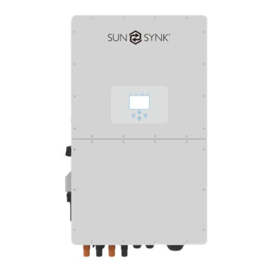
PRODUCT INTRODUCTION The Sunsynk Three-Phase Hybrid Inverter is a multifunctional inverter, combining functions of inverter, solar charger and battery charger to offer uninterruptible power support with portable size. Its comprehensive LCD display offers user configurable and easy accessible button operation such as battery charging, AC/solar charging, and acceptable input voltage based on different applications. -
Page 8: Product Size
Product Size Inverter Size THREE PHASE HI 29.9/50kW | User Manual... -
Page 9: Features
Features INTERACTIVE Easy and straightforward to understand LCD display; ƒ Supporting Wi-Fi or GSM monitoring; ƒ Visual power flow screen; ƒ 4 MPPT inputs and 2 strings per input; ƒ Smart settable 3-stage MPPT charging for optimised battery performance; ƒ Auxiliary load function;... -
Page 10: Basic System Architecture
Basic System Architecture The following diagram explains the basic application and architecture of this 3-Phase Inverter. It also includes the following devices to have a Complete running system. Generator or Utility ƒ PV modules ƒ Batteries ƒ Normal and smart loads ƒ... -
Page 11: Technical Specifications
TECHNICAL SPECIFICATIONS SUNSYNK-29.9K- SUNSYNK-30K- SUNSYNK-35K- SUNSYNK-40K- SUNSYNK-50K- Model SG01HP3-EU-BM3 SG01HP3-EU-BM3 SG01HP3-EU-BM3 SG01HP3-EU-BM4 SG01HP3-EU-BM4 Battery Input Data Battery Type Lithium-ion Battery Voltage 160~700V Max. Charging Current 50+50A Max. Discharging Current 50+50A Max. Charging/Discharging 29900W 33000W 38500W 44000W 55000W Power Charging Strategy for Li-Ion... - Page 12 Certifications and Standards Grid Connection Standard EN 50549-1, AS-NZS 4777.2, NRS 097-2-1; Additional connections available upon request EMC/Safety Standards IEC/EN 61000-6-1/2/3/4, IEC/EN 62109-1, IEC/EN 62109-2 General Data Operating Temperature Range -40 to +60ºC, >45ºC Derating Permissible Altitude Humidity 0~100% Permissible Altitude 2000m Noise <65 dB...
-
Page 13: Installation
INSTALLATION Parts List Check the equipment before installation. Please make sure nothing is damaged in the package. You should have received the items in the following package: Hybrid Inverter Wall Mounting Stainless Steel Anti-Colli- Bracket x1 sion Bolt M12x60 x4 Parallel Communication Stainless Steel Mounting L-type Hexagon Wrench... -
Page 14: Selecting The Mounting Area
Selecting the Mounting Area For proper heat dissipation, allow a clearance of approximately 500mm to the side, 500mm above and below the unit, and 1000mm to the front of the unit. DO NOT install the inverter in the following areas: Areas with high salt content, such as the marine environment. -
Page 15: Mounting The Inverter
If children under 10 years old may approach the unit, take preventive measures so they cannot reach ƒ and touch the unit. Install the indoor unit on the wall where the floor height is higher than 1600mm. ƒ Before connecting all wires, please take the metal cover off, removing the screws as shown below: Mounting the Inverter Select installation locations that are adequate to support the weight of the converter. -
Page 16: Battery Connection
Inverter Hanging Plate Installation Battery Connection For safe operation and compliance, an individual DC overcurrent protector or disconnection device is required to connect the battery and the inverter. Users are recommended to utilise a suitable fuse and DC isolator (see next page). Switching devices may not be required in some applications, but overcurrent pro- tectors must be used. - Page 17 Please follow below steps to implement battery connection: 1. Pass the cable through the terminal: 2. Put on the rubber ring: 3. Crimp terminals: 4. Fasten terminal with a bolt: 5. Fasten the terminal with outer cover: Battery Port Battery Port BMS connection BMS connection Pass the BMS communication cable...
-
Page 18: Function Port Definition
Function Port Definition Inverter Meter Parallel_1 Parallel_2 BMS1 BMS2 RS485 1 2 3 4 5 6 7 8 9 10 1112 1 2 3 4 5 6 7 8 9 10 11 12 SHUT DOWN Meter: For energy meter communication. Parallel A: Parallel communication port 1 (CAN interface). -
Page 19: Grid And Backup Load Connection
29.9/30/35/40/50KW model, the recommended AC breaker for grid is 240A. There are three terminal blocks marked as GRID, LOAD, and GEN. Please do not confuse input and output connections. External AC SPD is compulsory on all Sunsynk inverters. WARNING All wiring must be performed by qualified personnel. System safety and efficient operation need to use appropriate cable for AC input connection. -
Page 20: Pv Connection
1. Switch the Grid Supply Main Switch (AC) OFF. 2. Switch the DC isolator OFF. 3. Assemble PV input connector to the inverter. 4. Use the MC4 connectors supplied by Sunsynk with the inverter. THREE PHASE HI 29.9/50kW | User Manual... - Page 21 WARNING Before connection, please ensure the polarity of the output voltage of the PV array matches the DC+ and DC- symbols. Please do not connect the PV array's positive and negative poles to the system ground bar. This can seriously damage the inverter. Before connecting the inverter, please make sure the PV array open-circuit voltage is within the maxi- mum limit of the inverter.
-
Page 22: Connecting The Ct Coil
Connecting the CT Coil The CT coil is one of the most important parts of the Sunsynk inverter. This device reduces the power of the inverter to prevent feeding power to the grid. This feature is also known as “Zero Export”. -
Page 23: Meter Connection
NOTE: When the reading of the load power on the LCD is not correct, please reverse the CT arrow. When the inverter is in the off-grid state, the N line needs to be connected to the earth. For systems utilizing three or more inverters drawing over 300A from the grid, it's advisable to employ larger CTs (Current Transformers). -
Page 24: Eastron Meter
Eastron Meter GRID Inverter Meter Parallel_1 Parallel_2 RS485B RS485A 1 2 3 4 5 6 7 8 Eastron Grid (1,2,3,4) (5,6,7,8) B A G RS 485 RS 485 B RS 485 A Eastron meter Eastron SDM630-Modbus V2 THREE PHASE HI 29.9/50kW | User Manual... -
Page 25: Chint Meter With Ct Coil
CHINT Meter with CT Coil GRID Inverter Meter Parallel_1 Parallel_2 Breaker RS485A RS485B AC Breaker Home Load Three-Phase Smart Meter Grid 6 9 10 1314 16171921 (3,6,9,10) Three-Phase Smart Meter RS 485 CHiNT Meter 230/400V,3~ 250A/50mA 50/60Hz : CHNT DTSU666 THREE PHASE HI 29.9/50kW | User Manual... -
Page 26: Eastron Meter With Ct Coil
Eastron Meter with CT Coil GRID Inverter Meter Parallel_1 Parallel_2 AC Breaker Home Load AC Breaker NA LA L1 L2 L3 N Grid S1 S2 S1 S2 S1 S2 Black line Red line Black line Red line Black line Red line towards the inverter 9 1 0 11 1 2 1 3 1 4 1 5 1 6 1 7 1 8 1 9 2 0 Eastron... -
Page 27: Earth Connection (Mandatory)
Earth Connection (MANDATORY) Ground cable shall be connected to ground plate on grid side this prevents electric shock if the original pro- tective conductor fails. Earth Connection (Copper wires) (bypass) Model Wire Size Cable (mm Torque Value (max) 29.9/30/35/40/50kW 0 AWG 28.2Nm Earth Connection (Copper wires) Model... -
Page 28: Wiring System For Inverter
Wiring System for Inverter THREE PHASE HI 29.9/50kW | User Manual... -
Page 29: Wiring Diagram
Wiring Diagram THREE PHASE HI 29.9/50kW | User Manual... - Page 30 50A for each input. ②AC Breaker Backup Load ④AC Breaker Home Load ① DC Breaker for battery SUNSYNK-29.9K-SG01HP3-EU-BM3: 200A DC breaker SUNSYNK-30K-SG01HP3-EU-BM3: 200A DC breaker SUNSYNK-35K-SG01HP3-EU-BM3: 200A DC breaker SUNSYNK-40K-SG01HP3-EU-BM4: 200A DC breaker SUNSYNK-50K-SG01HP3-EU-BM4: 200A DC breaker ② AC Breaker for backup load SUNSYNK-29.9K-SG01HP3-EU-BM3: 240A AC breaker...
-
Page 31: Typical Application Of Diesel Generator
Inverter ①DC Breaker ②AC Breaker Battery pack ① DC Breaker for battery SUNSYNK-29.9K-SG01HP3-EU-BM3: 200A DC breaker SUNSYNK-30K-SG01HP3-EU-BM3: 200A DC breaker SUNSYNK-35K-SG01HP3-EU-BM3: 200A DC breaker SUNSYNK-40K-SG01HP3-EU-BM4: 200A DC breaker SUNSYNK-50K-SG01HP3-EU-BM4: 200A DC breaker Backup Load ② AC Breaker for backup load SUNSYNK-29.9K-SG01HP3-EU-BM3: 240A AC breaker... -
Page 32: Three Phase Parallel Connection
Three Phase Parallel Connection Note: For the parallel system, the lead-acid battery is not supported. Please use Sunsynk approved lithium battery. All inverters connected in parallel must be the same model. L wire N wire PE wire Inverter Meter Parallel_1 Parallel_2... -
Page 33: Operation
OPERATION Switching ON/OFF Once the inverter has been correctly installed and the batteries have been connected, press the ON/OFF button (located on the left side of the case) to activate the system. When the system is connected without a battery but connected with either PV or grid and the ON/OFF button is switched off, the LCD will still illumi- nate (display will show off). -
Page 34: Lcd Operation Flow Chart
LCD Operation Flow Chart Solar Page Solar Graph Grid Page Grid Graph Inverter Page Battery Page BMS Page HOME PAGE Load Page Load Graph Basic Setting Battery Settings Grid Settings System Mode System Setup Advanced Settings Aux Load Settings Fault Codes Li BMS Settings THREE PHASE HI 29.9/50kW | User Manual... -
Page 35: Home Page
Home page Press the Esc button any page to access the home page: 1. Customer name 2. Access the settings menu page 3. Access solar page 4. Access load page 5. Access battery page SOLAR/TURBINE AC load 6. Access grid page 7. -
Page 36: System Flow Page
What this page displays: Total solar power produced. Inverter voltage. ƒ ƒ MPPT 1 power/voltage/current. Inverter current. ƒ ƒ MPPT 2 power/voltage/current. Inverter heat-sink temperature. ƒ ƒ MPPT 3 power/voltage/current. UPS LD power/voltage. ƒ ƒ MPPT 4 power/voltage/current Battery power charge/discharge. ƒ... -
Page 37: Setup Page
What this page displays: The system flow. Battery status. ƒ ƒ MPPTs power. Power distribution to load or grid. ƒ ƒ Essential Loads Setup Page To access Settings, click on the gear icon on the right top of the navigation menu. What this page displays: Serial number. -
Page 38: Basic Setup
Basic Setup Set Time (Clock) To set time, click on the BASIC icon and then on ‘Time’ What this page displays: Time. ƒ Date. ƒ AM/PM. ƒ What you can do from this page: Adjust / set time. ƒ Adjust / set date. ƒ... -
Page 39: Factory Reset And Lock Code
Locked Inverter: This function is used to lock the inverter completely so no access can be gained. It will ask for a 5-digit code that only the Sunsynk Technical staff can assist with. Test mode (only for engineers): For engineers to conduct tests. -
Page 40: Inverter Remote Control
Inverter Remote Control To control the inverter remotely, tick the box that allows it. What this page displays: Remote control option. ƒ What you can do from this page: Allows remote control of the inverter. ƒ Battery Setup Page To configure battery settings, click on the BATTERY icon and then on ‘Batt type’. What this page displays: Lithium: This is BMS protocol. -
Page 41: Generator & Battery Page
Generator & Battery Page To configure battery charging settings, click on the BATTERY icon and then on ‘Batt Charge’. What this page displays: Amps: Charge rate of 40A from the attached generator in Amps. ƒ Grid Amps: Current that the grid charges the battery. ƒ... - Page 42 Recommended battery settings: Battery Type Absorption Stage Float Stage Voltage (every 30 days 3hr) Lithium Follow its BMS voltage parameters A generator can either be connected to the Grid side or to the Gen connection. When connected to the Grid Input, the inverter will consider the power coming from the generator as ‘Grid Supply'.
-
Page 43: Battery Discharge Page
Battery Discharge Page To configure inverter’s shut-down settings, click on the BATTERY icon and then on ‘Shut Down’. What this page displays: Shutdown 20%: It indicates the inverter will shutdown if the SOC is below this value. ƒ Low Batt 20%: It indicates the inverter will alarm if the SOC below this value. ƒ... -
Page 44: Setting Up A Lithium Battery
Setting Up a Lithium Battery To set up a lithium-ion battery, click on the BATTERY icon and visit the ‘Batt Type’ column. What this page displays: This information will only display if the ‘Lithium’ option is selected under ‘Batt Type’. ƒ... - Page 45 NOTE: With some types of lithium batteries, the BMS cannot be controlled by the Sunsynk inverter. In this case, treat the battery as a lead-acid type and set the charging and discharging protocol following the battery manufacturer's specifications. It is crucial to refer to the manuals that manufacturers produce for their batteries. That way, the chance of errors occurring during installation is significantly reduced.
- Page 46 FNS POWER SHSIFP512050A Dowell iPack CHV Series Sunova Ess GT4100-E Serie HVS Series/HVM Series CAN H: Pin 5 Sunsynk-G HV-Series CAN L: Pin 4 SUNSYNK CAN H: Pin 4 SUN-BATT-80 CAN L: Pin 5 BN624V-105-66K HV BN728V-105-77K HV CAN H: Pin 7...
-
Page 47: Program Charge & Discharge Times
Program Charge & Discharge Times To set ‘Charge’ and ‘Discharge’ times, click on the ‘System Mode’ icon after clicking on the gear icon. What this page displays: 1. Use Export Controller: Tick this box to not export power back to the grid (the CT coil will detect power flowing back to the grid and will reduce the power of the inverter only to supply the local load). - Page 48 7. Grid peak shaving: When this is selected, the grid output power will be limited within the set value. If the load power exceeds the allowed value, it will take PV energy and stored battery energy to supple- ment. If there is not enough PV energy or stored energy to meet the load requirement, grid power will increase to meet the load needs.
- Page 49 Zero Export to CT: The hybrid inverter will not only provide power to the backup load connected but also give power to the home load connected. If PV power and battery power are insufficient, it will take grid ener- gy as a supplement. The hybrid inverter will not sell power to the grid. In this mode, a CT is needed. For the installation method of the CT, please refer to the chapter "CT Connection".
- Page 50 Example 2: The power produced is supplying the ‘Non-Essential Load’ while the inverter is set at a maximum power of 50kW (Max Sell Power). The inverter is connected to the grid, but no export is performed. The unit allows small amounts of power to flow from the Grid (100W Zero Export Power) to prevent any back-flow. In this example, the solar PV is prioritised to supply the Load first and then subsequently, charge the battery.
-
Page 51: Grid Supply Page
Grid Supply Page In the Settings menu, click on the GRID icon. 220VAC 220VAC 220VAC Rz: Large resistance ground resistor. Or the system doesn't have a Neutral line. What this page displays: Grid Mode: General Standard - for example, UL1741 & IEEE1547, EN50549_CZ_PPDS_L16A, NRS097, ƒ... - Page 52 What this page displays: HV1: Level 1 overvoltage protection point; HF2: Level 2 over frequency protection point; ƒ ƒ HV2: Level 2 overvoltage protection point; HF3: Level 3 over frequency protection point. ƒ ƒ HV3: Level 3 overvoltage protection point. LF1: Level 1 under frequency protection point;...
- Page 53 What this page displays: V(W): It adjusts the inverter active power according to the set grid voltage. ƒ V(Q): It adjusts the inverter reactive power according to the set grid voltage. This function adjusts invert- ƒ er output (active and reactive) power when grid voltage changes. Lock-in/Pn 5%: When the inverter active power is less than 5% rated power, the VQ mode will not take ƒ...
-
Page 54: Paralleling Inverters Advanced Settings
NOTE: Only when the grid voltage is equal to or higher than 1.05 times the rated grid voltage will the P(PF) mode take effect. Paralleling Inverters Advanced Settings To configure multi-inverter settings, click on the ADVANCE icon. NOTE: Parallel feature is max up to 10 inverters. In parallel operation, the setting “Limit to load only”... - Page 55 The grid input must also be connected in parallel. ƒ If you need further help please refer to the Sunsynk website where you will find training videos and Fre- quently Asked Questions www.sunsynk.com. Firmware prior installation is important to be updated and all inverters in parallel or three phase system must be the same.
-
Page 56: Connecting The Drm's
Q7: What consequences for changing ALL/ANY settings while operating in parallel mode? It can damage the inverter and fault F46 will be indicated on the display. Connecting the DRM’s This can be selected under advance settings. *For AS4777 Standard. Inverter Load port Shell L1 L2 L3 N... -
Page 57: Solar Power Generated
Solar Power Generated This page shows the daily, monthly, yearly, and total solar power produced. Access this page by clicking on the ‘Solar/Turbine’ icon on the Home Page. Grid Power This page shows the Daily / Monthly / Yearly and total grid power export or consumed. Access this page by clicking on the ‘Solar/Turbine’... -
Page 58: Advanced Settings For Auxiliary Load
Advanced Settings for Auxiliary Load To configure Auxiliary Load (previously known as “smart load”) settings, click on the AUX LOAD icon. What this page displays: Use of the Gen (Aux) input or output. ƒ Generator peak shaving is ON or OFF. ƒ... - Page 59 Solar Power: Power limiter to the maximum power allowed to the Aux load. ƒ Aux Load OFF Batt Battery SOC at which the Smart load will switch off. ƒ Aux Load ON Batt: Battery SOC at which the Smart load will switch on. Also, the PV input power should ƒ...
-
Page 60: Operation Modes
OPERATION MODES Mode I: Basic AC cable DC cable COM cable Backup Load On-Grid Home Load Solar Battery Grid Mode II: With Generator AC cable DC cable Solar Backup Load On-Grid Home Load Grid Battery Generator THREE PHASE HI 29.9/50kW | User Manual... -
Page 61: Mode Iii: With Aux-Load
Mode III: With Aux-Load AC cable DC cable Solar Backup Load On-Grid Home Load Grid Battery Aux-Load Mode IV: AC Couple On-Grid+AC couple AC cable DC cable Solar Backup Load On-Grid Home Load Grid Battery On-Grid Inverter THREE PHASE HI 29.9/50kW | User Manual... -
Page 62: Mode V: Grid-Tied
The last power backup will be the Generator if it is available. WARRANTY For warranty details, please refer to the Warranty Statement suplyed by Sunsynk. Under our company's guidance, customers may return products for maintenance or replacement of equiv- alent value. Customers are responsible for shipping and associated costs. Any replaced or repaired product retains the remaining warranty period. -
Page 63: Troubleshooting
TROUBLESHOOTING To check the fault codes click on the FAULT CODES icon on the settings menu. Follow the solutions in the table below to troubleshoot issues. If these methods do not resolve the problem, please contact our after-sales service. Before contacting support, please gather the following information to expedite troubleshooting: Inverter Information: Include serial number, firmware version, installation date, fault occurrence time, ƒ... - Page 64 Error Code Description Solutions Check whether the FAN are connected correctly and operat- FAN_OUT2_Warn ing normally. Check whether the FAN are connected correctly and operat- FAN_OUT3_Warn ing normally. 1. Measure whether the grid port voltage is too high. VW_activate 2. Check whether the AC cable is too thin to carry current. Abnormal battery communication Battery_comm_warn 1.
- Page 65 Error Code Description Solutions AC side over current fault 1. Please check whether the backup load power and com- AC_OuverCurr_SW_Failure mon load power are within the range. 2. Restart and check whether it is normal. Leakage current fault GFCI_Failure 1. Check the PV side cable ground connection. 2.
- Page 66 Error Code Description Solutions 1. When in parallel mode, check the parallel communication cable connection and hybrid communication address set- tings. Parallel_Comm_Fault 2. During the parallel system startup period, inverters will re- port F29. When all inverters are in ON status, it will disappear automatically.
- Page 67 Error Code Description Solutions Grid frequency out of range 1. Check the frequency is in the range of specification or not. AC_UnderFreq_Fault 2. Check whether AC cables are firmly and correctly connect- AC_U_GridCurr_DcHigh_Fault Restart the inverter 3 times and restore the factory settings. AC_V_GridCurr_DcHigh_Fault Restart the inverter 3 times and restore the factory settings.
-
Page 68: Commissioning
COMMISSIONING Start-Up / Shutdown Procedure The inverter must be installed by a qualified / licensed electrical engineer in accordance with the country's wiring regulations. Before switching on, the installation engineer must have completed the Earth Bond, RCD and earth leakage tests, checked that the solar panel Voc voltage does not exceed 850V and checked the battery voltage. -
Page 69: Gdfi Fault
Ensure you are familiar This is the heart of the with this, if you fully under- See section ‘Program system this controlls stand the controller you Charge / Discharge Times’ everything will fully appreciate the ca- pabilities of there inverter If paralleling inverters in 3 Phase check your phase If using a wind turbine... - Page 70 Secondary output cable length is 4m. ƒ Lead Outside For more information, training videos, software upgrades, help line, forum please refer to http://www.sunsynk.com - Tech Support (Do not forget to register first on the website). Sunsynk @energysolutions sunsynkofficial THREE PHASE HI 29.9/50kW | User Manual...
- Page 71 HK Address: Room 702-704, 7/F Texwood Plaza, 6 How Ming Street, Kwun Tong, Kowloon, Hong Kong. UK Address: Sunsynk UK Ltd, 17 Turnstone Business Park, Mulberry Avenue, Widnes, Cheshire, WA8 0WN. SA Address: Globaltech Sunsynk South Africa (Pty) Ltd, Unit 2 Highview Boulevard, Ferndale 2194.
Need help?
Do you have a question about the SUNSYNK-29.9K-SG01HP3-EU-BM3 and is the answer not in the manual?
Questions and answers