Table of Contents
Advertisement
Quick Links
Photovoltaic Grid-connected
Microinverter(Built-in WIFI-G3)
INSTALLATION/USER MANUAL
SUN300G3-EU-230/SUN500G3-EU-230/SUN600G3-EU-230/
SUN800G3-EU-230/SUN1000G3-EU-230/SUN1300G3-EU-230/
SUN1600G3-EU-230/SUN1800G3-EU-230/SUN2000G3-EU-230
Global Tech China Ltd, 3 Floor, Wai Yip Industrial Building.
171 Wai Yip Street, Kwun Tong, Kowloon, Hong Kong.
Tel: +852 2884 4318 Fax: +8522884 4816
www.sunsynk.com / sales@sunsynk.com
v.2 (02/01/23)
Advertisement
Table of Contents

Related Manuals for SunSynk SUN300G3-EU-230


Summary of Contents for SunSynk SUN300G3-EU-230
- Page 1 Photovoltaic Grid-connected Microinverter(Built-in WIFI-G3) INSTALLATION/USER MANUAL SUN300G3-EU-230/SUN500G3-EU-230/SUN600G3-EU-230/ SUN800G3-EU-230/SUN1000G3-EU-230/SUN1300G3-EU-230/ SUN1600G3-EU-230/SUN1800G3-EU-230/SUN2000G3-EU-230 Global Tech China Ltd, 3 Floor, Wai Yip Industrial Building. 171 Wai Yip Street, Kwun Tong, Kowloon, Hong Kong. Tel: +852 2884 4318 Fax: +8522884 4816 www.sunsynk.com / sales@sunsynk.com v.2 (02/01/23)
-
Page 2: Table Of Contents
Table of Contents SAFETY 1. 1.1. General Safety 1.2. Safety Instructions 1.3. Radio Interference Statement 1.4. The Meaning of Symbols 2. MICROINVERTER SYSTEM INTRODUCTION 2.1. Microinverter Maximize PV Energy Production 2.2. More Reliable than Centralized or String Inverters 2.3. Simple to Install 3. MICROINVERTER INTRODUCTION 4. MICROINVERTER SYSTEM INSTALLATION 4.1. Additional Installation Components 4.2. Required Parts and Tools 4.3. Parts List 5. INSTALLATION PROCEDURES... - Page 3 12. HOW TO CONFIGURE THE MICROINVERTER TO THE ROUTER VIA 13. HOW TO CONNECT IN APP 13.1. Registration 13.2. Create a Plant 13.3. Add a Logger 13.4. Network Configuration MICRO INVERTER | User Manual...
-
Page 4: Safety
1. SAFETY 1.1. General Safety This manual contains important instructions to follow during the installation and maintenance of the ƒ Photovoltaic Grid-connected Inverter(Microinverter). To reduce the risk of electrical shock and ensure the safe installation and operation of the Microinverter, the following symbols appear throughout this document to indicate dangerous conditions and important safety instructions. -
Page 5: Safety Instructions
1.2. Safety Instructions DO NOT disconnect the PV module from the Microinverter without disconnecting the AC power. ƒ Only qualified professionals should install and/or replace the Microinverter. ƒ Perform all electrical installations in accordance with local electrical codes. ƒ Before installing or using the Microinverter, please read all instructions and cautionary markings in the ƒ... -
Page 6: The Meaning Of Symbols
1.4. The Meaning of Symbols Can be OEM Trademark. Caution, risk of electric shock. Caution, risk of burn - Do not touch. Caution, hot surface. The symbol for the marking of electrical and electronic devices according to Directive 2002/96/EC. Indicates that the device, accessories and packaging must not be disposed of as unsorted municipal waste and must be collected separately at the end of the usage. -
Page 7: Microinverter System Introduction
2. MICROINVERTER SYSTEM INTRODUCTION The Microinverter is used in utility-interactive grid-tied applications, comprised of two key elements: · Mi- croinverter · Router This series microinverter has a built-in WIFI module so it can communicate with the router directly. 300 / 500 / 600 / 800 / 1000G3 Meter Module Distribution Box... -
Page 8: Microinverter Maximize Pv Energy Production
PLEASE NOTE Suppose the wireless signal in the area where the micro inverter is weak. In that case, adding a wifi signal booster is necessary at a suitable place between the router and the microinverter. This integrated system improves safety; maximizes solar energy harvest; increases system reliability, and sim- plifies solar system design, installation, maintenance, and management. -
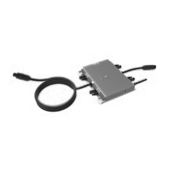
Page 9: Microinverter Introduction
For more information, please see this manual's Technical Data page (P17~20). Model Number AC grid Max. # Per branch SUN300G3-EU-230 50/60Hz, 230V 17 for 25A breaker SUN500G3-EU-230 50/60Hz, 230V 10 for 25A breaker... -
Page 10: Additional Installation Components
4.1. Additional Installation Components AC Male and Female Interconnection Connectors (sold separately) ƒ Sealing end caps(sold separately) ƒ 4.2. Required Parts and Tools In addition to your PV array and its associated hardware, you will need the following items: An AC connection junction box; ƒ... -
Page 11: Installation Procedures
5. INSTALLATION PROCEDURES Step 1: Install the AC branch circuit junction box. a. Install an appropriate junction box at a suitable location on the PV racking system (typically at the end of a branch of modules). b. Connect the open wire end of the AC cable into the junction box using an appropriate gland or strain relief fitting. - Page 12 AC cable L=120m m AC cable L=1940m m - 08 - AC cable L=120mm AC cable L=1940mm 300 / 500G3 (1MPPT) 600 / 800 / 1000G3 (2MPPT) Mounting AC cable L=1960m m AC cable L=85m m 1300 / 1600 / 2000G3 (4MPPT) Mounting The AC wire on the micro inverter is a TC-ER wire with a wire cross-section area of 3.33mm².
- Page 13 Step 3: Connect the microinverter in parallel. 300/500G3 (1MPPT) 1300/1600/2000G3 (4MPPT) 600/800/1000G3 (2MPPT) Connect in parallel Connect in parallel a. Check the Microinverter technical data page 5 for the maximum allowable number of Microinverter on each AC branch circuit. b. Plug the male AC connector of the Microinverter into the female connector to get it connected. AC con- nector interface is as follows.
- Page 14 Step 4: Install an AC cable protective end cap at the end of AC cable. Step 5: Connect microinverter to the PV modules. PLEASE NOTE When plugging in the DC cables, if AC is already available, the Microinverter should immediately blink red light and will start work within the set time (default 60 seconds).
-
Page 15: Microinverter System Operating Introductions
6. MICROINVERTER SYSTEM OPERATING INTRODUCTIONS 6.1. To operate the microinverter PV system 1. Turn ON the AC circuit breaker on each microinverter AC branch circuit. 2. Turn ON the main utility-grid AC circuit breaker. Your system will start producing power after a one-min- ute waiting time. -
Page 16: Troubleshooting
7. TROUBLESHOOTING Qualified personnel can use the following troubleshooting steps if the PV system does not operate correctly: 7.1. Status Indications and Error Reporting Status Error Reporting One minute after DC power is first applied to the microinverter; one short red blinks indicate a successful microinverter startup sequence, be equal to or Start up LED greater than two short red blinks after DC power is first applied to the mi- croinverter indicate a failure during the microinverter setup... - Page 17 2. Diagnosing from the network: No-Data-Display: The website and APP does not display any data. Check the network configuration. ƒ Only display microinverter is online but no data. This may be because the server is updating. ƒ To troubleshoot a non-operating Microinverter, follow the steps below in order: 1.
-
Page 18: Replacement
8. REPLACEMENT Follow the procedure below to replace a failed Microinverter: 1. Disconnect the Microinverter from the PV Module, in the order shown below: a. Disconnect the AC by turning off the branch circuit-breaker. b. Disconnect the AC connector of the microinverter. Cover the module with an opaque cover. -
Page 19: Technical Data
9. TECHNICAL DATA 9.1. 300G3/500G3/600G3 Specification Model SUN300G3-EU-230 SUN500G3-EU-230 SUN600G3-EU-230 Input Data (DC) Recommended 210~400W 210~600W 210~400W Maximum input DC voltage MPPT voltage Range 25~55V Operating DC voltage Range 25~60V Max DC short circuit current Max input current 10.5A x1 12.5A x1 10.5A x2... -
Page 20: 800G3/1000G3 Specification
9.2. 800G3/1000G3 Specification Model SUN800G3-EU-230 SUN1000G3-EU-230 Input Data (DC) Recommended input power (STC) 210~600W Maximum input DC voltage MPPT voltage Range 25~55V Operating DC voltage Range 25~60V Max DC short circuit current Max input current 12.5A x2 Output Data (AC) Rated output power 800W 1000W Maximum output power... -
Page 21: 800G3/1000G3 Specification
9.3. 800G3/1000G3 Specification Model SUN1300G3-EU-230 SUN1600G3-EU-230 SUN1800G3-EU-230 SUN2000G3-EU-230 Input Data (DC) Recommended input pow- 210~400W 210~600W 210~600W 210~600W er (STC) Maximum input DC voltage MPPT voltage Range 25~55V Operating DC voltage 25~60V Range Max DC short circuit cur- rent Max input current 10.5A x4 12.5A x4 12.5A x4... - Page 22 Features Compatibility Compatible with 60,72 cell PV modules Communication Power line / Wifi / Zigbee Compliance EN50549,VDE0126,VDE4105,IEC62109,CE,INMETRO Warranty 10 Years WARNING Ensure that your PV module's voltage and current specifications match those of the Microinvert- ƒ er. Please refer to the datasheet or user manual. You must match the DC operating voltage range of the PV module with the allowable input volt- ƒ...
-
Page 23: Wiring Diagrams
10. WIRING DIAGRAMS Sample Wiring Diagram Three Phase MICRO INVERTER | User Manual... - Page 24 Sample Wiring Diagram Single Phase MICRO INVERTER | User Manual...
- Page 25 Sample Wiring Diagram Three Phase MICRO INVERTER | User Manual...
- Page 26 Sample Wiring Diagram Single Phase MICRO INVERTER | User Manual...
-
Page 27: Monitoring Platform
11. MONITORING PLATFORM This series Microinverter has built-in WIFI modular, which is able to connect the router directly. For WIFI “B -in WIFI Modular Microinverter WIFI Configuration ”. Web monitoring address: https://pro.solarmanpv.com; (for Solarman distributor account) https://home.solarmanpv.com (for Solarman end-user account) For a mobile phone monitoring system, scan the QR code to download the APP. -
Page 28: How To Configure The Microinverter To The Router Via Web
12. HOW TO CONFIGURE THE MICROINVERTER TO THE ROUTER VIA WEB 1. Turn on the wireless network of your PC or smartphone. 2. Select the logger network (network name: AP_SN) and connect. The default password is 12345678. Safe Microinverter SN Safe Safe Safe 3. - Page 29 4. Browser jumps to “ Status ” page, the basic information is listed there. Status Inverter information Help Wizard Inverter serial number Quick Set Firmware version(main) The device can be used as Advanced Firmware version(slave) a wireless access point(AP mode) to facilitata users to Upgrade Inverter model configure the device, or it...
- Page 30 6. Enter the password and click Next. Status Help Wizard Quick Set Please fill in the following information: Most systems support the Advanced function of DHCP to obtain IP address automatically. Upgrade Please select disable and Password(8-64 bytes) add it manually if your router Restart (Note: case sensitive) does not support such...
- Page 31 8. If the setup is successful, the following page will pop up and click OK to reboot the micro inverter. Status Help Wizard Setting complete! Quick Set After clicking OK,the system will restart Advanced Click OK, the settings will take effect and the system will immediately.
-
Page 32: How To Connect In App
10. If remote servers A and B are "Not connected", please refresh the page or repeat the previous steps. If the "Signal Quality" is lower than 40%, please move your Router closer to the Microinverter. 13. HOW TO CONNECT IN APP 13.1. Registration Open the app of SOLARMAN Smart and register an account. -
Page 33: Add A Logger
13.3. Add a Logger Optional 1: Enter the logger SN manually. Optional 2: Click the icon in the right and scan the QR code to enter logger SN. You can find logger SN on the carton packaging or on the logger body. MY Plants Logger hinzufugen Create a Plant... - Page 34 Step 1: Confirm Wi-Fi Info Please make sure your phone has connected to the right WiFi network. And click "Start to configure". PLEASE NOTE 5G WiFi is not supported. Special characters (e.g.. ;‘’ =” ” `) in router name and password are not sup- ported.
- Page 35 WLAN settings Go toW LAN Setting and connect the following network manually WLAN Android MY NETWORKS ChinaNet AP_622602179 AP_622602179 Android HYH123 IGWN-5G ChinaNet IGWN-HILINK AP_622602179 HYH123 AP_622602179 IGWN-5G Password OTHER NETWORKS Show advanced options act-blue ChinaNet-igen Step 3: Auto Configuration Please wait for a while to complete the configuration.
- Page 36 wered by...
Need help?
Do you have a question about the SUN300G3-EU-230 and is the answer not in the manual?
Questions and answers