Advertisement
Quick Links
Advertisement

Subscribe to Our Youtube Channel
Related Manuals for Erica Synths SYNTRX II


Summary of Contents for Erica Synths SYNTRX II
- Page 1 USER MANUAL...
-
Page 2: Table Of Contents
TABLE OF CONTENTS FEATURES THE INTERFACE CONNECTIONS THE “MODULES” THE PATCH PATCH MATRIX PATCH MATRIX BUILDING MATRIX CONNECTIONS IN USE PATCHES MIDI CONFIGURATION SAFETY DISPOSAL IMPLEMENTATION SETTINGS INSTRUCTIONS... - Page 3 Universal 12VDC wall wart adapter around our signature matrix mixer and topped off with powerful FX on our new DSP platform. Introducing The SYNTRX II - a new dark User manual horse for experimental sonic rides.
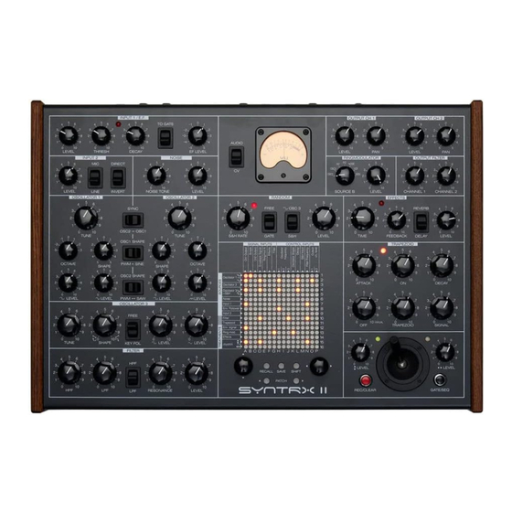
- Page 4 THE INTERFACE The SYNTRX II, like most synthesizers built around a patch matrix, is somewhat similar to a modular synthesizer – here you can modulate any available “module” with another and possible connections are almost limitless (it does not mean, however, that every connection will produce sound).
- Page 5 This is the MIDI input. The This is the first, main control voltage input. so if nothing is patched into inputs, the SCOPE SYNTRX II receives MIDI Connect any 1V/octave CV source (a OUT is automatically routed to both INPUTS...
- Page 6 THE “MODULES” As mentioned above, using the matrix patchbay on the SYNTRX II, you can build patches and achieve unconventional modulations. In order to fully understand the functionality of the SYNTRX II, let’s take a closer look at the individual “modules”.
- Page 7 OSCILLATOR 2 OSCILLATOR 2 SYNC OSCILLATOR 2 is also primarily an audio rate oscillator and without external CV applied, it generates pulse and saw waves at frequencies from approximately C0 to C8. The OCTAVE switch allows for offsetting the oscillator three octaves up or OSC2 OSC1 TUNE...
- Page 8 NOISE GENERATOR NOISE The SYNTRX II has a Zener diode-based NOISE GENERATOR that provides full spectrum white noise. The Noise Generator is not voltage controlled, but the COLOUR knob allows for emphasizing low (LOW setting) or high (HIGH setting)
- Page 9 Inputs of the SYNTRX II. Signal A is assignable on the matrix mixer’s Ringmod A input, while signal B is selected by rotary switch SOURCE B. Depending on the input signal frequency relationship, the output is a complex set of component tones, typically metallic, bell-like sounds.
- Page 10 9, the looping is terminated and a new envelope cycle can be initiated by pressing the GATE button next to the joystick controller. If the SYNTRX II is used with external CV/Gate signals (connected to CV and Gate inputs correspondingly)
- Page 11 EFFECTS EFFECTS REVERB The SYNTRX II has great-sounding DELAY and REVERBERATION effects, developed in collaboration with www.112db.com. The switch allows for selecting between the effects, while the TIME knob adjusts the delay time (3ms – 5 seconds) for the delay effect or room size for the reverberation effect. The FEEDBACK knob...
- Page 12 INPUT 1 TO GATE The SYNTRX II has two external audio signal inputs and you can use the instrument as an FX unit for external signal treatment or to inject the external signal into advanced patches and generate completely new sounds.
- Page 13 INPUT 2 INPUT 2 DIRECT INPUT 2 comes with a gain switch that selects between LINE level signals in the input and MICROPHONE level signals (this setting is also recommended for guitar pickups). Select the input amplifier gain and adjust the signal level with the LEVEL LEVEL LINE INVERT...
-
Page 14: The Patch Matrix
THE PATCH MATRIX The SYNTRX II has a digitally controlled analogue PATCH MATRIX. SIGNAL INPUTS CONTROL INPUTS It’s a mixer/buffered multiple matrix, so when designing patches, you can mix up to 16 inputs to a single output without loosing signal strength and likewise –... - Page 15 PATCH MATRIX CONNECTIONS Inputs (or receives) are: Outputs (or sends) are: Ch1 Output Pulse output of Oscillator 1 The input of the output amplifier for Channel 1 Oscillator 1 Scope Sine output of Oscillator 1 The input of the level meter Output of Oscillator 2 –...
- Page 16 Sequential patch change. Push < PATCH > buttons to change patches instantly. With each push of a button, the patch matrix will advance to the next (or previous) saved patch. This is a very handy feature when designing live performances with the SYNTRX II.
- Page 17 CONTROL INPUTS THE SEQUENCER The patch matrix on the SYNTRX II can be used as a piano roll sequencer that allows you to create up to 16 step sequences with notes within a 3 octave range. The output control voltage of the sequencer is automatically routed to all three Oscillator 1 Oscillators.
- Page 18 As mentioned above, the sequencer has a hidden feature – two stepped modulation sources; a CV from these is added to the joystick. This allows you to assign controlled, stepped modulations to any destination on the SYNTRX II via the Oscillator 1 patch matrix and offset/transpose them with the joystick.
- Page 19 Building patches on the patch matrix requires a non-linear approach that is bit different form patching a regular synthesizer. Without a patch designed, the SYNTRX II will not make any sound. When connecting the modules, you basically go in circles in and out of the patch matrix. Here are some examples.
- Page 20 OUTPUT AMPLIFIER 1 TRAPEZOID FILTER In this patch the pulse wave signal from the Oscillator 1 goes into the input of the SIGNAL INPUTS CONTROL INPUTS Filter and the output of the Filter is patched into the VCA (Envelope signal) linked to the envelope generator (Trapezoid).
- Page 21 OUTPUT AMPLIFIER 1 TRAPEZOID FILTER In this patch the pulse wave signal from the Oscillator 1 goes into the input of SIGNAL INPUTS CONTROL INPUTS the Filter and the output of the Filter is patched into the VCA (Envelope signal) linked to the envelope generator (Trapezoid).
- Page 22 OUTPUT AMPLIFIER 1 OUTPUT AMPLIFIER 2 This is an example of the patch that provides stereo panning effect. The pulse SIGNAL INPUTS CONTROL INPUTS wave signal from the Oscillator 1 goes to both Output Channel 1 and Output Channel 2. Make sure, both LEVEL knobs on the Output Amplifiers are set to desired volume and the Channel 1 is panned all way left, while the Channel 2 is panned all way right.
- Page 23 OUTPUT AMPLIFIER 1 TRAPEZOID EFFECTS This is an example of a basic patch with EFFECTS. The pulse wave signal from the SIGNAL INPUTS CONTROL INPUTS Oscillator 1 is connected to the input of the VCA (Envelope Signal), and the output of the VCA is routed both to Channel 1 Output and Effects module input.
-
Page 24: Midi Implementation
VCF cutoff. The SYNTRX II receives only one MIDI note at a time, and it is higher note priority. If no external CV is patched into the relevant inputs, MIDI note messages control... -
Page 25: Configuration Settings
CONFIGURATION SETTINGS All configuration settings on the SYNTRX II are done via the patch matrix. In order to access the configuration settings, push and hold the SHIFT button and push the < PATCH button. The configuration setting screen will appear. - Page 26 MIDI CC TO X allows you to add external modulation to any parameter of the the options are 0 – 16, where 0 is OMNI mode – the SYNTRX II receives MIDI SYNTRX II via the X axis of the joystick. The screen shows CC X (running line - messages from all channels.
-
Page 27: Safety Instructions
DISPOSAL SAFETY INSTRUCTIONS This device complies with EU guidelines and is Please follow the instructions for the use of the Erica Synths manufactured and confront RoHS without the use of lead, SYNTRX II below, because only this will guarantee the mercury, cadmium or chrome.
Need help?
Do you have a question about the SYNTRX II and is the answer not in the manual?
Questions and answers