Table of Contents
Advertisement
Quick Links
Advertisement
Table of Contents

Related Manuals for Trane BACnet BCI-I


Summary of Contents for Trane BACnet BCI-I
- Page 1 Installation Guide BACnet® BCI-I Used With S_HF 20-75 Tons S_HG 90-130 Tons S_HJ 90-162 Tons W_HB Casings 2-9 W_HC Casings A-C BACnet® is a registered trademark of the American Society of Heating, Refrigeration and Air-conditioning Engineers Inc. (ASHRAE.) RT-SVN13A-EN March 2009...
-
Page 2: Overview
Control Networks (BACnet) to give customers the flexibility to choose the best possible vendor for their building subsystems and easily incorporate Trane products into legacy systems in existing buildings. It is intended to be installed by a qualified System lntegrator who is properly trained and experienced in BACnet. -
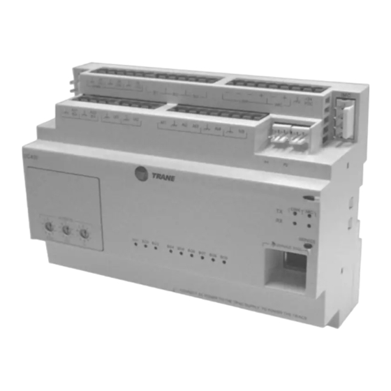
Page 3: Bci-I Controller Module - Physical Specifications
Warnings, Cautions and Notices BCI-I Controller Module — Physical Specifications Dimensions Height: 4.00 inches (101.6 mm) Width: 5.65 inches (143.6 mm) Depth: 2.17 inches (55 mm) Operating environment -40° to 70°C (-40° to 158°F) 5% to 95% relative humidity non-condensing Storage environment -44°C to 95°C (-48°F to 203°F) 5% to 95% relative humidity non-condensing... -
Page 4: Table Of Contents
Table of Contents Overview ........... . 2 Introduction . -
Page 5: Installation
Qty 1 - Sheet metal mounting bracket (IntelliPak only) • Qty 1 - 7.5 inch DIN rail Contact the Trane Parts Center nearest your area should there be any damaged or missing components. Mounting the Module Refer to the appropriate figure (Figure 2, p. - Page 6 Installation Note: Once all the screws are removed, the top cover plate and the module will be free from the mounting plate. Remove and discard the Heat Module Cover Plate. 3. Disconnect the wires from one end of the Heat Module by unplugging the connectors. Move the module away from its mounting plate.
- Page 7 Installation Figure 2. 20-25 Ton BCI Kit 1U49 1U107 Bracket Bracket Included with Kit Heat 1U50 1U48 1U105 Bracket 1TB9 24VAC Bracket 1U104 ECEM 1U52 Bracket IPCB 1U55 GBAS 1U51 Mounting Plate Bracket Mounting Plate 1U53 RT-SVN13A-EN...
-
Page 8: Ton Bci Kit
Installation Figure 3. 30 Ton BCI Kit Bracket 1U107 1TB9 Bracket 1U105 ECEM 1U48 1U52 Bracket Mounting Bracket Plate Bracket IPCB 1U49 1U55 Included Heat with Kit 1U50 Bracket 24VAC GBAS 1U51 1U104 1U53 Mounting Plate RT-SVN13A-EN... -
Page 9: Ton Bci Kit
Installation Figure 4. 40, 60, 70, 75 Ton BCI Kit Bracket 1U107 Included Bracket 1U49 with Kit Heat 1U48 1U50 1U105 24VAC Bracket 1TB9 Bracket 1U104 ECEM 1U52 Bracket Bracket GBAS 1U51 Mounting Plate IPCB 1U55 Mounting Plate 1U53 RT-SVN13A-EN... -
Page 10: Ton Bci Kit
Installation Figure 5. 50-55 Ton BCI Kit 1U107 1U49 Bracket Bracket Included with Kit Heat 1U50 1U105 1TB9 1U48 24VAC Bracket 1U104 Bracket ECEM 1U52 IPCB 1U55 Mounting Plate GBAS Bracket 1U51 Bracket 1U53 Mounting Plate RT-SVN13A-EN... - Page 11 Installation Figure 6. 90, 105, 115, 130 Ton BCI Kit 1U48 Bracket GBAS 1U51 1U49 Mounting Plate Bracket 1TB9 Bracket Bracket 1U53 ECEM 1U52 Bracket HEAT 1U50 Mounting IPCB Plate 1U55 24VAC Included with Kit 1U104 Figure 7. Factory-installed mounting method (IntelliPak I only) 24VAC 1U104 RT-SVN13A-EN...
-
Page 12: Mounting Or Removing The Uc400 Controller
Installation Figure 8. IntelliPak II Rooftop 90-150 Ton/Air Handler Casing A-C Mounting or Removing the UC400 Controller To mount or remove the controller from the DIN rail, follow the illustrated instructions below. NOTICE Equipment Damage! Do not use excessive force to install power supply to the DIN rail. Excessive force could result in damage to the plastic enclosure. -
Page 13: Intellipak I-Bci-I Wiring Harness Installation
Installation Figure 9. DIN Rail Mounting/Removal Pry upward Slotted release clip shown from backside To mount device: 1. Hook device over top of DIN rail 2. Gently push on lower half of device in the direction of arrow until the release clip clicks into place (see left image, Figure To remove or reposition device:... -
Page 14: Intellipak Ii-Bci-I Wiring Harness Installation
Installation 6. Comm Link Harness - Connect the 1/4" spade connector on wire 533B to 1TB5-19. Connect wire 534B to 1TB5-20. 7. Secure the harness wires within the control panel to the existing wire bundles. Coil any excess wire and secure as well. 8. - Page 15 Installation Figure 10. Connecting 24 VAC Transformer and Ground 24 Vac Transformer Note: The user must connect the chassis ground and the 24 VAC (see Step RT-SVN13A-EN...
- Page 16 Date March 2009 Supersedes www.trane.com For more information, contact your local Trane Trane has a policy of continuous product and product data improvement and reserves the right to office or e-mail us at comfort@trane.com change design and specifications without notice.
Need help?
Do you have a question about the BACnet BCI-I and is the answer not in the manual?
Questions and answers