Table of Contents
Advertisement
Quick Links
Installation, Operation, and Maintenance
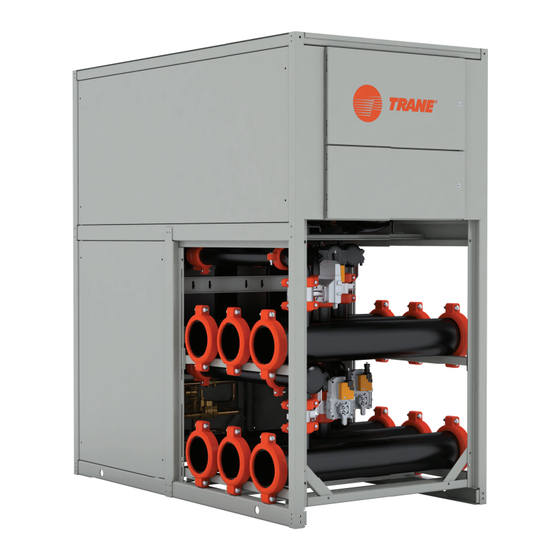
Thermafit™ Modular Water-Source
Multipipe
Model MWS
Only qualified personnel should install and service the equipment. The installation, starting up, and servicing of heating, ventilating, and air-conditioning equipment
can be hazardous and requires specific knowledge and training. Improperly installed, adjusted or altered equipment by an unqualified person could result in death or
serious injury. When working on the equipment, observe all precautions in the literature and on the tags, stickers, and labels that are attached to the equipment.
June 2024
SAFETY WARNING
ARTC-SVX011A-EN
Advertisement
Table of Contents

Related Manuals for Trane Thermafit MWS Series


Summary of Contents for Trane Thermafit MWS Series
- Page 1 Installation, Operation, and Maintenance Thermafit™ Modular Water-Source Multipipe Model MWS SAFETY WARNING Only qualified personnel should install and service the equipment. The installation, starting up, and servicing of heating, ventilating, and air-conditioning equipment can be hazardous and requires specific knowledge and training. Improperly installed, adjusted or altered equipment by an unqualified person could result in death or serious injury.
- Page 2 (HCFCs). Not all refrigerants containing these compounds bump cap, fall protection, electrical PPE and arc have the same potential impact to the environment. Trane flash clothing). ALWAYS refer to appropriate advocates the responsible handling of all refrigerants.
- Page 3 This document and the information in it are the property of regulations are more stringent than these Trane, and may not be used or reproduced in whole or in policies, those regulations supersede these part without written permission. Trane reserves the right to policies.
-
Page 4: Table Of Contents
Table of Contents Model Number and Coding ....6 Rigging, Lifting, and Moving the Multipipe ....... . 21 Multipipe Model and Serial Numbers . - Page 5 Table of Contents Analog Inputs......40 Simultaneous Mode – Heating Analog Outputs ..... . . 41 Dominant .
-
Page 6: Model Number And Coding
For future reference, record the model number and serial nameplate that is affixed to each module. number for each module in the table below. Refer to the Trane nameplate on each module in the installed unit for the serial number and model number. Table 1. Multipipe reference data... -
Page 7: Multipipe Description
Multipipe Description Multipipe Capacities The MWS multipipe uses a single refrigeration circuit in each module using fixed speed tandem scroll compressor Multipipe model is available in 30-, 40-, 50-, and 60-ton set. The brazed-plate evaporator is typically made of SAE capacity modules. - Page 8 Multipipe Description Cabinet operating, the hydronic system can have variable primary flow to the water source multipipe modules. The valves Cabinet panels are made of formed sheet metal powder open slowly - to minimize the sudden change in flow to the coated with an oven baked finish.
- Page 9 Multipipe Description NOTICE Proof of Flow Switch! Failure to provide flow switches or jumping-out of switches could result in severe equipment damage. Evaporator and condenser water circuits require proof of flow switches. • Failure to include the proof of flow devices and/or jumping out these devices could cause the unit to stop on a secondary level of protection.
-
Page 10: General Data
General Data Table 2. General data – Thermafit™ MWS water-source multipipe Capacity (Tons) General Unit Refrigerant Type R-454B R-454B R-454B R-454B Number of Independent Refrigeration Circuits Refrigerant Charge (lbs/circuit) Fluid Volume (gal/module) 40.9 43.2 60.7 64.9 Unventilated Room Area (sq.ft.) 17366 29817 45613... -
Page 11: Unit Dimensions And Weights
Unit Dimensions and Weights Figure 1. Dimensions and weight – Thermafit MWS (30 and 40 tons module) Table 3. Dimensions and weight – Thermafit MWS (30 and 40 tons module) 30 Tons 40 Tons 28.5 28.5 18.5 18.5 Wt (lbs) 1800 2000 ARTC-SVX011A-EN... - Page 12 Unit Dimensions and Weights Figure 2. Dimensions and weight – Thermafit MWS (50 and 60 tons module) Table 4. Dimensions and weight – Thermafit MWS (50 and 60 tons module) 50 Tons 60 Tons 34.6 34.6 29 / 28.8 29 / 28.8 8.75 / 9.5 8.75 / 9.5 Wt (lbs)
-
Page 13: Pre-Installation
See Figure 3, p. For vibration isolation, spring isolators or rubber-in-shear Note: Each installation has specific considerations. Contact isolator pads must be installed under the structural steel Trane for definitive guidance on a job-by-job basis. mounting rails. ARTC-SVX011A-EN... - Page 14 Pre-Installation Figure 3. Recommended multipipe clearances ARTC-SVX011A-EN...
- Page 15 Pre-Installation Figure 4. Recommended water-source multipipe module rigging For modules mounted directly on concrete, vibration setting each module, remove front or rear access panels to isolation pads can be installed under each module. After improve access to components when making connections. ARTC-SVX011A-EN...
-
Page 16: Operating Principles
Operating Principles The Thermafit™ MWS water-source multipipe is a state-of- In cooling mode, the diverting valves direct the load cooling the-art six-pipe multipurpose system featuring independent fluid to the evaporator and simultaneously direct the water circuits to satisfy end user's requirements for heating source/sink fluid to the source/sink brazed plate heat and cooling year-round. -
Page 17: A2L Work Procedures
At all times, Trane’s maintenance and service guidelines • Do not puncture refrigerant tubing. shall be followed. In in doubt, contact Trane technical support for assistance. • Dispose of properly in accordance with federal or local regulations. -
Page 18: Leak Detection
Use control settings, where available. When not available, manually open all electronically controlled valves using • Replace electrical components with Trane replacement acceptable service procedures. parts, or those meeting the same ratings and qualified for flame arrest protection, UL LZGH2 category. -
Page 19: Decommissioning
A2L Work Procedures • Cylinders shall be kept in an appropriate position a. Mechanical handling equipment is available, if according to the instructions. required, for handling refrigerant cylinders. • Ensure that the refrigerating system is earthed prior to b. All personal protective equipment is available charging the system with refrigerant. -
Page 20: Installation Mechanical
Verify the correct model number and that all skids and cartons have been delivered. Any damage must be Long Term Storage reported to the motor carrier and Trane within five days of receipt of the shipment. Requirements Inspect all exterior components for concealed damage as Appropriate preparation and storage of Thermafit™... -
Page 21: Customer Responsibilities
Failure to adhere to these long-term storage requirements • Do not exceed the product ratings or maximum may void the Trane warranty. Any component that is limits. Products rated only for basic insulation damaged or inoperable due to improper storage may have must be installed on insulated conductors. - Page 22 Installation Mechanical • Rig, lift, and move by strapping and lifting, by overhead • Do not use cables, chains, or any other type of means or using a properly configured floor jack or fork metalized strapping to lift a module. lift •...
-
Page 23: Installation Piping
Installation Piping Install Piping and External the pipes. A 40-mesh screen strainer must be installed in each water/liquid system piping inlet for proper filtration Components and protection of the heat exchangers. The following figure provides a recommended installation of components. Proper support of piping and pipe hangers must consider the weight of the piping as well as the water weight inside Figure 5. -
Page 24: Installation Electrical
Installation Electrical Wiring and Piping Labeled control and communication cables are coiled inside each module and are connected to an Ethernet Modules must be installed in accordance with the switch. The Ethernet cable turns from the switch to each manufacturer’s recommendations where shown on the module’s microprocessor controller at the J30 connector. -
Page 25: Phase Monitor Installation
Installation Electrical Figure 7. Typical controller network Phase Monitor Installation WARNING Hazardous Voltage! The water-source multipipe unit is equipped with a phase monitor on the power distribution panel. It is connected to Failure to disconnect power before servicing could the corresponding microprocessor controller digital input. result in death or serious injury. -
Page 26: Operating Procedures
Operating Procedures Operator Interface Panel-Mounted Disconnect Switch Some water–source multipipe systems are optionally All water–source multipipe units, whether they are equipped with a panel-mounted disconnect switch installed composed of a three modules (minimum) or up to 10 on the outside of the power distribution panel (or on each modules, are automated systems that use a touchscreen module’s electrical and control panel if the system has interface panel to monitor, report, and modify critical... -
Page 27: Electronic Control
Operating Procedures Module Electrical and Control Panel There are five BMS communication options: Note: BMS is not included as standard, but available as an The electrical and control panel receives power from the option. power distribution panel and provides power to the individual electrical components in that module. -
Page 28: Microprocessor Functions
The touchscreen interface panel is used to adjust set (‘tech’) and administrator (‘admin’) levels that can only be points, clear alarms, and perform detailed setup of the accessed by Trane technical personnel. Contact Trane microprocessor controllers. technical support regarding the possibility of any potential issues involving the higher-level functions. -
Page 29: Touchscreen Interface Tutorial
Operating Procedures Touchscreen Interface Tutorial Each of the main screens in the interface contains active hot spots to activate virtual buttons and switches by simply This section consists of a tutorial that first-time personnel touching the screen. can use to navigate through the various functions and features that are available in the interface. -
Page 30: Home Screen Features
Operating Procedures Home Screen Features Feature Description 1 - HMI Software Version Calls up the pop-up window. See figure below. • Project Name: HMI software project name • Software Version: HMI software version • Consists of 4 two-digit numbers – First two numbers stand for major and minor software revision. - Page 31 Operating Procedures Feature Description 5 - Setpoint Calls up cooling/heating setpoint pop-up screens respectively depending on the mode – accessible for 'tech' only. These dialog boxes display the resulting cooling/heating setpoint used for machine temperature control. Figure 15. Cooling setpoint Figure 16.
- Page 32 Operating Procedures Feature Description 7 - System Status Possible Options: • System ON – system is operational and is not off by any of the conditions listed below. • Phase Alarm – system is off by Phase Alarm if common Phase Monitor is used per multipipe. •...
-
Page 33: Modules Layout Screen
Operating Procedures Feature Description 12 - Module Access There are buttons to access all modules screens individually. Number on the button “M(X)” stands for the module number in the bank. Buttons are viewable (modules accessible) for modules that communicate to HMI only. Each module menu includes the following set of screens: •... -
Page 34: Active Alarms Screen
Operating Procedures Table 5. Module status conditions Module turned off by alarm and unavailable Module is unavailable Module is available Module in Cooling Mode Module in Simultaneous Mode Module in Heating Mode Isolation Valves: - Valve LED is green = valve is open - Valve LED is gray = valve is closed Refrigeration circuit in normal state Refrigeration circuit in alarm state... -
Page 35: Alarm History
Operating Procedures Select Time This column indicates if the alarm is selected or unselected This column is the date-time stamp indicating exactly when for acknowledgment or resetting. the alarm occurred. Action Description This column gives alarm details if applicable This column provides alarm description or for certain alarms, snapshots of module parameters values. - Page 36 Operating Procedures next to the heading indicates which column is being sorted and the direction of sorting. Sorting is applied to the alarm time column in ascending order by default, which is indicated when the triangle is pointing up. Ascending order for the alarm time column requires that earlier records appear on the list first.
-
Page 37: Module Access
Operating Procedures For instance, one needs to view only events when alarms modules that communicate to HMI only. Each module occurred and hide all other ones (aka one alarm event for menu includes the following set of screens. each alarm). •... - Page 38 Operating Procedures Overview 1 – Module Note: Stand-alone module operates as independent multipipe module and controls Module En/Dis cooling / heating temperatures locally based on its Evaporator / Condenser EWT / LWT Pressing this button enables or disables a module. If depending on cooling / heating / module is disabled, it's excluded from primary control simultaneous mode and control temperature...
- Page 39 Operating Procedures Heat Exchangers Note: Lead Module is the module which always starts first. When there are no compressors running, Lead Displays each heat exchanger Evaporator/Condenser/ Module always keeps its Isolation Valves open. Source inlet and outlet temperatures as well as opening (depending on the mode) to allow for chilled/hot status of its Isolation Valves.
-
Page 40: Module I/O Screens
Operating Procedures Communication • Heat Temp Diff +/- — Heating temperature control differential above/below setpoint or positive/negative Comm LED indicates if PLC is communicating to dead band (DB). compressor control device. Local Temp Cntrl Module I/O Screens Applies only if module is running in stand-alone mode. Data is collected by sensors as either analog or digital •... -
Page 41: Analog Outputs
Operating Procedures AI12 closed – no power supply issues; DI opened – power supply failure detected. If common power supply protection This input indicates Liquid Line Pressure. module is used for the multipipe, its failure will affect each Note: All Analog Inputs are Universal Inputs (UI). Each UI module. -
Page 42: Expansion Io Screen 1
Operating Procedures Expansion IO Screen MWS Primary Expansion I/O Screen#1 MWS Primary/Secondary Expansion I/O Screen#2 Expansion IO Screen 1 Green LED — valve reached respective position. This screen applies only to the primary module. This Gray LED — specified valve position not reached. screen controls analog inputs and digital requests. - Page 43 Operating Procedures Figure 21. Cooling trend screen Table 8. Trend screen labels Label Description According to where the cursor is placed, it is capturing real time values of in and out water temperatures. Current cursor timestamps are displayed as well. Text box to select viewing time span.
-
Page 44: Operator Tasks
Operating Procedures Figure 22. Heating trend screen 1. De-energize the multipipe using standard lockout/ tagout procedures. 2. Using a known operational voltage meter, test and confirm the unit is de-energized before proceeding further. 3. Inspect power distribution fuses and overload settings to verify they are correct. -
Page 45: Water Quality Guidelines
Total Hardness 4.5 - 8.5 dH° Note: Trane will not validate the multipipe warranty if proper < 1.0 ppm Free Chlorine water/glycol mixture composition and quality is not Ammonia (NH <... -
Page 46: Prevent Freezing
Trane does not warranty any component that fails set up like glass. The first type of behavior due to freezing. - Page 47 Operating Procedures The precise concentration of glycol for a particular unit is plug in the bottom of the evaporator, the inhibitors in an affected by several key factors such as ambient approved glycol solution will best protect the surfaces of temperature extremes, entering and leaving water the evaporator against oxidation if the glycol remains inside temperatures, and system size.
-
Page 48: Controls Interface
Controls Interface Multipipe Controls a phase monitor to protect against low voltage, phase imbalance, phase loss, and phase reversal conditions. Each system is provided with a touchscreen interface panel Each water-source multipipe control system includes that is used to turn the water-source multipipe system on operational switches for each compressor;... -
Page 49: Microprocessor Control System
Controls Interface Figure 26. MWS touchscreen interface panel Microprocessor Control System microprocessor controller fails. The system automatically fails-over to distributed primary control where each Thermafit™ MWS water-source multipipe models employ a secondary controller operates its own module in the normal Carel c.pCO all-digital data control system to control and fashion, but lacks the ability to rotate the lead compressors report key system settings and indicators. -
Page 50: Low Pressure Bypass
In applications where it is desired to operate with a lower flow rate or higher This logic uses a time delay that temporarily bypasses the temperature change, consult Trane technical support for low-pressure switch for compressor start-up. Once the recommendations. -
Page 51: Sequence Of Operations
Sequence of Operations This manual describes a typical water-source multipipe Multipipe Bank Thermal Mode can be adjusted at Chiller system with few, if any, optional components or devices Bank UI or communicated from BAS. attached. Multipipe Bank Sequence Building Automation System Multipipe Bank can be enabled from either BAS or Chiller (BAS) Controls System Bank UI. -
Page 52: Dominant
Sequence of Operations Simultaneous Mode – Cooling Dominant Cooling Mode Cooling prevalence occurs when Cooling Demand gets If heating is no longer required, all modules switch over to ahead of Heating Demand. This happens when either Cooling Mode. Hot Water pumps, however, stay running, Cooling Demand increases or Heating Demand decreases. -
Page 53: Start-Up
Start-Up Preparation for Initial Start-Up 7. Inspect all refrigerant pressures for each module to confirm no refrigerant has been lost. After the system is completely installed with all wires 8. Confirm the oil level is correct in each compressor. connected and all piping securely coupled, the multipipe system can be prepared for initial start-up. - Page 54 Check the box if there are any customer-supplied devices connected to the multipipe wiring. ☐ List devices: ______________________________________________________________________________________ Check the box if there are any Trane remote devices connected to the multipipe wiring. ☐ Check the box if voltage drops are detected.
- Page 55 Start-Up Table 12. Initial start-up readiness checklist (continued) Start-Up Readiness Dimension ☐ ☐ Check the box if high voltage wiring is installed, tested, and functional. ☐ Check the box if all control wiring between modular units is installed, tested, and functional. ☐...
-
Page 56: Maintenance Procedures
The primary goal of preventive maintenance is to avoid the • Weekly or monthly periodic maintenance involves consequences of failure of equipment. Trane equipment is cleaning specific components and inspecting glycol and designed to be easily accessed for servicing. lubrication fluids. -
Page 57: Federal Clean Air Act
Maintenance Procedures NOTICE may have additional requirements that must be followed to responsibly handle HVAC refrigerants. Component Damage! Failure to follow instructions could damage sensitive Inspection and Maintenance electronic components beyond repair. Schedule To prevent arcing or surges of electrical current, do not use wires or cables to jump components or Proactive measures should be taken to prevent potential bypass the manufacturer's safety systems. -
Page 58: Weekly
Maintenance Procedures Table 13. Recommended equipment service intervals (continued) Frequency Task Confirm and record compressor amperage draw and voltage Annually Compare fluid flow against design specifications Annually Weekly Note: A flashlight may be required to see the oil churning in the sump of the compressor. -
Page 59: Annually
Maintenance Procedures 1. Inspect alarm log, refrigerant operating/static 1. Inspect all electrical connections for damage and pressures, and temperature set points of each module ensure terminals are tight. Inspect all contactors for independently. pitting and corrosion and replace as necessary. 2. - Page 60 Maintenance Procedures 11. Inspect all insulation on piping and control sensors. 14. If equipped, inspect crankcase heaters to verify proper Repair and replace as necessary. operation. 12. Inspect entire plumbing system for leaks. 15. Sample refrigerant to analyze for moisture or acid. 13.
-
Page 61: Multipipe Troubleshooting
Isolation Fault detection is recognizing that a problem has occurred, Trane manufactures equipment with embedded fault even if the root cause is not yet known. Fault isolation is the detection and diagnostics in each module’s controller that... - Page 62 Multipipe Troubleshooting Table 14. MWS module alarm summary (continued) Primary / Secondary Type Alarm Action cpCOe #2 Offline Alarm Primary / Secondary Auto Reset Locks out module cpCOe #2 wrong config Alarm Primary / Secondary Warning Auto Reset Primary / Secondary Differential Pressure low User Reset Locks out module...
-
Page 63: Compressor Diagnostic Codes
Compressor Diagnostic Codes CoreSense™ Flash Codes If equipped, the CoreSense technology in the Copeland Copeland compressors used in Trane equipment are highly compressor will communicate an abnormal system automated with digital capability to record and report a condition through a unique flash code: range of operating parameters and critical events. - Page 64 Multipipe Troubleshooting Table 15. CoreSense™ communications LED flash code information (continued) Code Fault Code Reset Description Trouble Shooting Information Status Fault Condition Description Module and master controller have lost Check the control wiring Green Flash Loss of When communications are communications with Code 1 Communication...
-
Page 65: Phase Monitor Protection
Multipipe Troubleshooting Phase Monitor Protection If the phase monitor fails to energize (the LED glows red) check wiring of all three phases, voltage, and phase If the system fails to power up, eliminate electrical phase sequence. If phase sequence is incorrect, the LED flashes issues by inspecting the phase monitor device located in green/red. - Page 66 Multipipe Troubleshooting 2. Symptom: Compressor will not run Possible Causes Potential Solutions Breakers and switches are off Confirm all breakers and switches are on. Main switch open or circuit breakers open Check circuits and motor winding for shorts or grounds. Replace fuse or reset breakers.
- Page 67 Multipipe Troubleshooting 6. Symptom: Low refrigeration suction pressure Possible Causes Potential Solutions Clogged liquid line filter-drier Replace filter drier or cartridges. Excessive glycol concentration Charge to proper glycol concentration. Liquid line solenoid restricted or faulty Replace solenoid valve, coil, or internals as necessary. Insufficient water in evaporator (cooling) and source (heating) Adjust flow rate through heat exchanger.
- Page 68 Multipipe Troubleshooting 11. Symptom: High chilled water temperature Possible Causes Potential Solutions Load higher than capacity of unit Refer to design specifications. Loss of refrigeration charge Check refrigerant charge. Fouled evaporator (cooling) or source (heating) BPHEs Reverse flush evaporator; check strainer for debris. High water flow rate Check pump, VFD and differential pressure settings.
- Page 69 Multipipe Troubleshooting 17. Symptom: Freeze protection safety activated Possible Causes Potential Solutions Unit setpoint is too low Use a proper setpoint. Clean strainer; check pump, VFD and differential pressure settings. Low water flow Low suction pressure See “low suction pressure”. ARTC-SVX011A-EN...
-
Page 70: Request For Initial Start-Up
Trane at least 10 working days prior As part of a continuous commitment to quality, initial start- to the scheduled initial start-up date. - Page 71 Request for Initial Start-Up Name (Printed): ____________________________________ Date: ______________________________________ Signature: _________________________________________ Company: __________________________________ ARTC-SVX011A-EN A–2...
- Page 72 For more information, please visit trane.com or tranetechnologies.com. Trane has a policy of continuous product and product data improvements and reserves the right to change design and specifications without notice. We are committed to using environmentally conscious print practices.
Need help?
Do you have a question about the Thermafit MWS Series and is the answer not in the manual?
Questions and answers