Advertisement
Quick Links
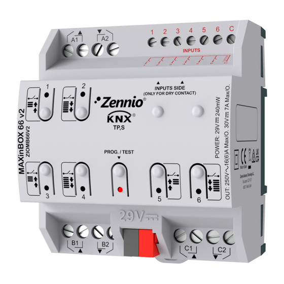
Multifunction actuator with 6 outputs and 6 inputs
ZIOMB66V2
FEATURES
•
3 different configurable channels: shutter channels (up to 3) and individual
outputs (up to 6)
•
Outputs suitable for capacitive loads, maximum 140 µF.
•
6 analog/digital inputs.
•
Manual output operation with push button and LED Status indicator.
•
10 logic functions.
•
Output timing.
•
Total data saving on KNX bus failure.
•
Integrated KNX BCU.
•
Dimensions 67 x 90 x 79 mm (4.5 DIN units).
•
DIN rail mounting (EN 50022), with fixing clamp.
•
Possibility of connecting different phases in adjacent outputs.
•
Conformity with the CE directives (CE-mark on the right side).
1. Analog/Digital inputs
5. Programming/test
LED
Programming/Test button: short press to set programming mode. If this button is held while plugging the device into the KNX bus, it enters the safe
mode. If this button is held for more than 3 seconds, the device enters the test mode.
Programming/Test LED: programming mode indicator (red). When the device enters the safe mode, it blinks (red) every half second. The manual mode
is indicated by the green color. During the start-up (reset or after KNX bus failure) and if the device is not in safe mode, it starts a blue blinking sequence.
GENERAL SPECIFICATIONS
CONCEPT
Type of device
Voltage (typical)
Voltage range
KNX supply
Maximum
consumption
Connection type
External power supply
Operation temperature
Storage temperature
Operation humidity
Storage humidity
Complementary characteristics
Protection class
Operation type
Device action type
Electrical stress period
Degree of protection
Installation
Minimum clearances
Response on KNX bus failure
Response on KNX bus restart
Operation indicator
Weight
PCB CTI index
Housing material
¹ Maximum consumption in the worst case scenario (KNX Fan-In model)
© Zennio Avance y Tecnología S.L.
2. Upper outputs
6. Lower outputs
7. KNX Connector
Voltage
29VDC (typical)
24VDC¹
Edition 1
3
4
5
3. Output status LED indicator
8. Programming/test
DESCRIPTION
Electric operation control device
29VDC SELV
21..31VDC
mA
4.57
10
Typical TP1 bus connector for 0.80mm Ø rigid cable
Not required
0°C .. +55°C
-20°C .. +55°C
5 .. 95% (No condens.)
5 .. 95% (No condens.)
Class B
II
Continuous operation
Type 1
Long
IP20, clean environment
Independent device to be mounted inside electrical panels with DIN rail (EN
50022)
Not required
Data saving according to parameterization
Data recovery according to parameterization
The programming LED indicates programming mode (red) and test mode
(green). Each output LED indicates its status
172g
175V
PC FR V0 halogen free
Futher information
MAXinBOX 66 v2
TECHNICAL DOCUMENTATION
2
6
Figure 1: MAXinBOX 66 v2
4. Output control button
9. Fixing clamp
button
mW
132.53
240
www.zennio.com
1
8
7
9
Page 1/2
Advertisement

Related Manuals for Zennio MAXinBOX 66 v2


Summary of Contents for Zennio MAXinBOX 66 v2
- Page 1 • Possibility of connecting different phases in adjacent outputs. • Conformity with the CE directives (CE-mark on the right side). Figure 1: MAXinBOX 66 v2 1. Analog/Digital inputs 2. Upper outputs 3. Output status LED indicator 4. Output control button 5.
- Page 2 ZN1IO-DETEC-P * The micro switch number 2 in the ZN1IO-DETEC-P must be in Type B position to work properly. ** Zennio temperature probe or any NTC with known resistance values at three points in the range [-55, 150ºC]. SAFETY INSTRUCTIONS •...