Zennio ZoningBOX 6 User Manual
Ducted air zoning actuator for 6 / 4 zones
Hide thumbs
Also See for ZoningBOX 6:
- Technical documentation (2 pages) ,
- Technical documentation (2 pages)

Related Manuals for Zennio ZoningBOX 6


Summary of Contents for Zennio ZoningBOX 6
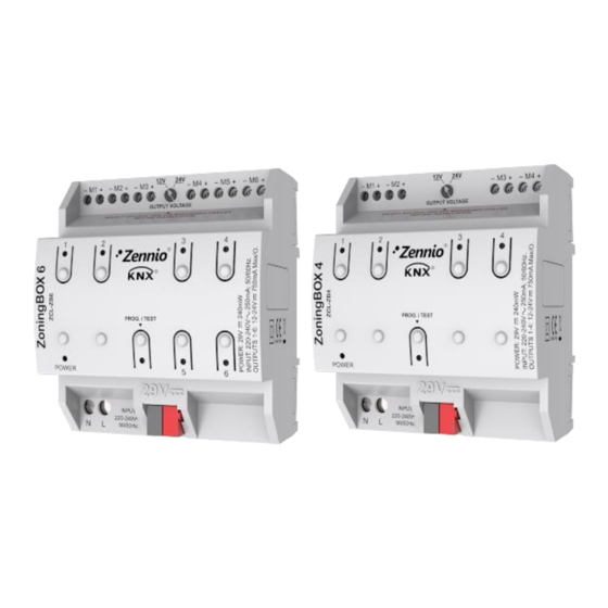
- Page 1 ZoningBOX 6 / ZoningBOX 4 Ducted Air Zoning Actuator for 6 / 4 Zones ZCL-ZB6 ZCL-ZB4 Application program version: [2.1] User manual edition: [2.1]_a www.zennio.com...
-
Page 2: Table Of Contents
ZoningBOX 6 / ZoningBOX 4 CONTENTS Contents ............................2 Document Updates ........................3 Introduction .......................... 4 1.1 ZoningBOX 6 / ZoningBOX 4 ..................... 4 1.2 Installation ........................5 1.3 Start-Up and Power Loss ....................6 Configuration......................... 7 2.1 General ..........................7 2.2 Zones .......................... -
Page 3: Document Updates
ZoningBOX 6 / ZoningBOX 4 DOCUMENT UPDATES Version Changes Page(s) Changes in the application program: [2.1]_a • New parameter for advanced current control Changes in the application program: • New operating mode: positional control. • Optimisation of the global setpoint temperature calculation. -
Page 4: Introduction
1 INTRODUCTION 1.1 ZoningBOX 6 / ZoningBOX 4 ZoningBOX 6 and ZoningBOX 4 from Zennio are two versatile KNX actuators intended for the climate management of rooms (or zones) where the air flow inputs are regulated through motorised gates or grilles. -
Page 5: Installation
Prog./Test pushbutton. Prog./Test LED. KNX Connection. Figure 2. Element diagram (ZoningBOX 6) The main elements of the device are described next. Prog./Test Pushbutton (7): a short press on this button sets the device into the programming mode, making the associated LED (3) light in red. -
Page 6: Start-Up And Power Loss
ZoningBOX 6 / ZoningBOX 4 To get detailed information about the technical features of this device, as well as on the installation and security procedures, please refer to the corresponding Datasheet, bundled with the original device packaging and also available at www.zennio.com. -
Page 7: Configuration
In such case, for practical purposes please consider them as a sole grille. This document and its figures are generally referred to ZoningBOX 6. However, note that all functions are entirely analogous in ZoningBOX 4. - Page 8 ZoningBOX 6 / ZoningBOX 4 Zoning [disabled/enabled]: enables o disables the “Zones” tab on the left menu. See section 2.2 for more details. Grille Control [enabled]: enables o disables the “Grilles” tab on the left menu. See section 2.3 for more details.
-
Page 9: Zones
2.2.1 CONFIGURATION ZoningBOX 6 / 4 can control up to 12 climate zones, which can be grouped into one or two groups, depending on whether there is one or two HVAC units in the installation. - Page 10 This option is recommended for the cooling mode. ZoningBOX 6 / 4 permits one bypass to be set for each enabled zone group, avoiding overpressures in the air ducts, for example if all grilles are closed. Setting from how many closed grilles are to be forced open is also possible.
- Page 11 ZoningBOX 6 / ZoningBOX 4 Grilles Maintenance: ZoningBOX can perform maintenance actions to prevent seize and dust in the grilles. This consists in automatically opening the grille once it is found to have been closed for more than one week. After thirty seconds it gets closed again.
- Page 12 ZoningBOX 6 / ZoningBOX 4 ➢ “[Unit x] On/Off HVAC Unit (Status)”: one-bit object to receive feedback about the on/off state of HVAC unit “x”. This object must be grouped with the analogous object of the HVAC unit interface. ➢ “[Unit x] Global Temperature Setpoint”: 2-Byte object that will be sent whenever the temperature setpoint for HVAC unit “x”...
- Page 13 ZoningBOX 6 / ZoningBOX 4 ➢ “[Group n] [Gi] [Control] Grille Status”: one-bit or 1-Byte object for receiving the feedback of the grille status. This is typically to be grouped with the analogous object in the Grilles module (see section 2.3).
- Page 14 ZoningBOX 6 / ZoningBOX 4 The parameters in this part depend on the Operating Mode: Open/Close Mode: If enabled, the “[Unit x] Bypass” one-bit object will be available, which must be linked to the analogous object of the interface that controls such valve.
- Page 15 ZoningBOX 6 / ZoningBOX 4 • Desired Position with no Demand [0…20…100%]: opening of the grill actuates as bypass when it is close because it is enabled and has no demand or is disabled. For each HVAC unit (1-2), it is also possible to configure: Delay to Close Last Grille / Bypass [0…1…255 s]: sets a time delay prior to...
-
Page 16: Grille Control
ZoningBOX 6 / ZoningBOX 4 2.2.2 GRILLE CONTROL This tab sets the opening states depending on control variable values. ETS PARAMETERISATION Figure 14 – Grill Control Intermediate Control Point 1 [0…35…100%]: sets a limit under which every control order received with a value between 0% and Intermediate Control Point 1, will implies an opening value of Grille Position 1 [0…20…100%]. -
Page 17: Mode
ZoningBOX 6 / ZoningBOX 4 2.2.3 MODE Each HVAC unit works necessarily under one of the following operation modes at a time, which therefore is applied to all zones included in its group: Heating: the unit will generate hot air to warm the zones. The grille control will be intended to make the local reference temperature reach the zone setpoint temperature. - Page 18 ZoningBOX 6 / ZoningBOX 4 Joint mode (one byte): a 1-Byte object is provided together with the corresponding status object, coded according to the following table. Mode KNX Value Heating Cooling Dry Air Table 1 Modes Simplified mode (one bit): a one-bit object is provided to allow simple changeovers between Cooling (value “0”) and Heating (value “1”).
-
Page 19: Fan
ZoningBOX 6 / ZoningBOX 4 Individual Modes: enables the “[Unit x] Cool Mode”, “[Unit x] Heat Mode”, “[Unit x] Fan Mode” and “[Unit x] Dry Mode” one-bit objects, as well as their corresponding status objects. Simplified Mode: enables the “[Unit x] Simplified Mode” and “[Unit x] Simplified Mode (Status)”... - Page 20 ZoningBOX 6 / ZoningBOX 4 …… Speed 1 Speed N Speed 2 (Minimum) (Maximum) Figure 18. Cyclic step control The “Off” state may be interpreted by the HVAC gateway as a switch-off order or as an order to switch to the automatic fan control, depending on its configuration.
- Page 21 ZoningBOX 6 / ZoningBOX 4 Percentage DPT_Scaling Fan Speed Object Value Value Ignore Order 1 – 33% 1 - 85 34 – 67% 86 - 170 68 – 100% 171 - 255 Table 5. Percentage fan control – three speeds...
- Page 22 ZoningBOX 6 / ZoningBOX 4 ETS PARAMETERISATION The options that can be parameterised from the Fan tab are: Figure 19. Zones – Fan CONTROL OBJECTS Individual Control (1 bit) [disabled/enabled]: enables one binary object for each fan speed level available in each HVAC unit (either two or three; see below): ➢...
- Page 23 ZoningBOX 6 / ZoningBOX 4 ➢ Type [No cyclic / Cyclic]: indicates whether the step control will be cyclic or not. Enumeration Control (1 byte) [disabled/enabled]: enables the “[Unit x] Fan: Enumerated Control” 1-Byte object, which represents each fan level by integer values between 0 and 3 (or 0 and 2, when corresponding).
-
Page 24: Temperature Setpoint
ZoningBOX 6 / ZoningBOX 4 Number of Fan Speeds / 3]: sets how many fan speed levels are implemented in the HVAC unit. Fan Mode [Auto / Manual / Auto + Manual]. The behaviour and parameters of each option are explained in the following sections: ➢... - Page 25 ZoningBOX 6 / ZoningBOX 4 Cool Mode: T − Max (0, RInt (Max(T − T REF i Example 1 – Heating mode: Return Temp. to the unit (T ) = 19ºC Zone 1 Reference Temp. (T ): 21ºC; Setpoint Temp. (T ): 25ºC...
- Page 26 ZoningBOX 6 / ZoningBOX 4 Once the global setpoint has been calculated, the following corrections will be applied in order (only in the Cooling and Heating modes), if configured, every time the setpoint of any of the zones changes. Temperature range.
-
Page 27: Scenes
ZoningBOX 6 / ZoningBOX 4 Temperature Range [disabled/enabled]: enables the global setpoint restriction in the groups: ➢ Minimum (Cool Mode) [16…30 ºC]: minimum global setpoint allowed to be sent to the HVAC unit. ➢ Maximum (Heat Mode) [16…30 ºC]: maximum global setpoint allowed to be sent to the HVAC unit. - Page 28 ZoningBOX 6 / ZoningBOX 4 Note: ZoningBOX does not support scene saving. ETS PARAMETERISATION Figure 22. Zoning - Scenes After having enabled the Scenes function from the Configuration tab (see section 2.2.1), the “Scenes” object will become available, together with the following parameters: Scene n [disabled/enabled]: enables or disables scene “n”...
-
Page 29: Reset
ZoningBOX 6 / ZoningBOX 4 • Fan Speed [No Change / Minimum / Intermediate / Maximum]: fan speed level to be set on the execution of the scene (the actual options will depend on the fan configuration; see section 2.2.4). - Page 30 ZoningBOX 6 / ZoningBOX 4 Note: enabling the last two options together (status and status requests) may cause contradictory situations if their delays are not properly configured. It is advisable to send the status requests prior to any other sending.
-
Page 31: Grilles
This module is in charge of managing the motorised grilles that let the air flow enter the zones, when corresponding. Please refer to the Datasheet, bundled with the original device packaging and also available at www.zennio.com, for details on the technical requirements to ensure compatibility with each particular grille model... -
Page 32: Grille
ZoningBOX 6 / ZoningBOX 4 ETS PARAMETERISATION Figure 24. Grilles - Configuration After enabling Grille Control from the General parameter screen (see section 2.1), the following options will be available for configuration: Grille “y” [disabled/enabled]: sets how many grilles (i.e., zones) will be controlled by the device, up to six. - Page 33 ZoningBOX 6 / ZoningBOX 4 A closing time for the connected grille (positional mode exclusive). An additional time, to force further motion once the end-of-stroke position has been reached. The initial position, which will be adopted by the grille after a bus power failure or at the end of an ETS download.
-
Page 34: Error Notification
ZoningBOX 6 / ZoningBOX 4 Initial Position [No Change / Open / Close / Position]: sets the action to be performed by the grille after the start-up of the device. If “Position” is selected, exclusive for positional mode, the following parameter will be displayed: ➢... - Page 35 ZoningBOX 6 / ZoningBOX 4 Power supply failure: this is reported in case the input voltage differs from 230 VAC. In such case, grille operation is immediately interrupted. Overheating: this is reported in the unlikely event that ZoningBOX detectes an internal temperature of 75º C or more. In such case, all grilles will remain stopped until it lowers back to 65º...
- Page 36 ZoningBOX 6 / ZoningBOX 4 Note: while Test On mode is active, only the connection error will be notified through LED as an aid to testing the installation. If a serious error occurs, as power supply or overheating failure, it will be notified after Test On mode finishes.
- Page 37 ZoningBOX 6 / ZoningBOX 4 detects the internal temperature is abnormally high. It will be sent with value “0” once this situation is over. The error objects are sent periodically (every thirty seconds) while their value is “1”. However, once they adopt the value “0” they are only sent once.
-
Page 38: Manual Control
ZoningBOX allows manually operating the the grilles hrough the respective pushbuttons on the top of the device (one push button per grille). Contrary to other Zennio devices, ZoningBOX only provides manual operation in Test On mode (for testing purposes during the configuration of the device). This control mode allows direct control over the outputs with independence of the configuration and of the grille states, although some safety restrictions apply, as explained below. - Page 39 ZoningBOX 6 / ZoningBOX 4 ETS PARAMETERISATION The Manual Control is configured from the Configuration tab itself under Manual Control, as long as this function has been enabled in General (see section 2.1) Figure 27. Manual Control As the only manual control mode available in this device is the Test On mode, it will get enabled simply by enabling the manual control function.
-
Page 40: Annex I. Interaction Between Modules
ZoningBOX 6/ ZoningBOX 4 ANNEX I. INTERACTION BETWEEN MODULES [Unit x] On/Off HVAC Unit (Status) [Unit x] On/Off HVAC Unit [Unit x] Modo [Unit x] Mode (status) HVAC Unit [Unit x] Temperature Restriction Gateway [Unit x] Global Temperature Setpoint [Unit x] Min. Limit Temperature [Unit x] Fan: Speed (status) [Unit x] Max. -
Page 41: Annex Ii. Communication Objects
ZoningBOX 6/ ZoningBOX 4 ANNEX II. COMMUNICATION OBJECTS “Functional range” shows the values that, with independence of any other values permitted by the bus according to the object size, may be of any use or have a particular meaning because of the specifications or restrictions from both the KNX standard or the application program itself... - Page 42 ZoningBOX 6/ ZoningBOX 4 1=Heat 3=Cool 9=Fan 14=Dry 92, 125 1 Bit C - W T U DPT_Ack [Unit x] Heat Mode 0 = Ignored; 1 = Activate Heat Mode 93, 126 1 Bit C R - T - DPT_Switch [Unit x] Heat Mode (Status) 0 = Off;...
- Page 43 ZoningBOX 6/ ZoningBOX 4 117, 150 1 Bit C R - T - DPT_Switch [Unit x] Fan: Speed Maximum (Status) 0 = Off; 1 = On 1 Bit C - W T U DPT_Switch [Unit x] Fan: Auto/Manual 0 = Manual; 1 = Auto...
- Page 44 Join and send us your inquiries about Zennio devices: http://support.zennio.com Zennio Avance y Tecnología S.L. C/ Río Jarama, 132. Nave P-8.11 45007 Toledo (Spain). Tel. +34 925 232 002. www.zennio.com info@zennio.com...
Need help?
Do you have a question about the ZoningBOX 6 and is the answer not in the manual?
Questions and answers