
Subscribe to Our Youtube Channel
Related Manuals for Zennio MAXinBOX SHUTTER 4CH


Summary of Contents for Zennio MAXinBOX SHUTTER 4CH
- Page 1 MAXinBOX SHUTTER 4CH / 8CH v2 4-Channel / 8-Channel Shutter Actuator ZIOMBSH4V2 ZIOMBSH8V2 Application program version: [1.2] User manual edition: [1.2]_a www.zennio.com...
-
Page 2: Table Of Contents
MAXinBOX SHUTTER 4CH / 8CH v2 CONTENTS Contents ........................... 2 Introduction ........................3 1.1 MAXinBOX SHUTTER 4CH / 8CH v2 ................3 1.2 Installation ........................4 1.3 Start-Up and Power Loss ....................5 Configuration ........................6 2.1 General ........................6 2.2 Outputs ........................ -
Page 3: Introduction
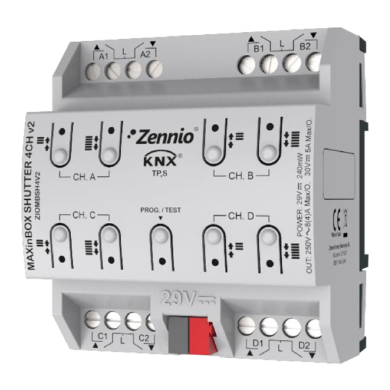
MAXinBOX SHUTTER 4CH / 8CH v2 1 INTRODUCTION 1.1 MAXinBOX SHUTTER 4CH / 8CH v2 MAXinBOX SHUTTER 4CH v2 and MAXinBOX SHUTTER 8CH v2 from Zennio are KNX specific actuators (of 4 or 8 channels, respectively) for controlling motorised shutter / blind systems. -
Page 4: Installation
MAXinBOX SHUTTER 4CH / 8CH v2 1.2 INSTALLATION MAXinBOX SHUTTER 4CH / 8CH v2 connects to the KNX bus through the on-board KNX connector. Once the device is provided with power from the KNX bus, both the individual address and the associated application program may be downloaded. -
Page 5: Start-Up And Power Loss
MAXinBOX SHUTTER 4CH / 8CH v2 Manual control pushbuttons (6): pushbuttons for a direct control of the shutter channels during the set-up process. See section 2.5. To get detailed information about the technical features of this device, as well as on the... -
Page 6: Configuration
MAXinBOX SHUTTER 4CH / 8CH v2 2 CONFIGURATION 2.1 GENERAL After importing the corresponding database in ETS and adding the device into the topology of the desired project, the configuration process begins by entering the Parameters tab of the device. - Page 7 MAXinBOX SHUTTER 4CH / 8CH v2 Manual Control [disabled/enabled]: enables o disables the “Manual Control” tab on the left menu. See section 2.5 for more details. Sending of Indication Objects (0 and 1) on Bus Voltage Recovery [disabled/enabled]: this parameter lets the integrator activate two new communication objects (“Reset 0”...
-
Page 8: Outputs
For detailed information about the functionality and the configuration of the parameters related to the shutter channels, please refer to the specific manual “Shutters”, available in the MAXinBOX SHUTTER 4CH / 8CH v2 product section at the Zennio homepage (www.zennio.com). -
Page 9: Scene Temporisation
MAXinBOX SHUTTER 4CH / 8CH v2 2.4 SCENE TEMPORISATION The scene temporisation allows imposing delays over the scenes of the shutter channels. These delays, defined in parameters, are applied on the execution of one or more scenes that may have been configured. - Page 10 MAXinBOX SHUTTER 4CH / 8CH v2 Figure 6. Configuration of Scene Temporization Therefore, parameter “Scene m. Shutter Channel Z Delay” [0…3600 [s] / 0…1440 [min] / 0…24 [h]], defines the delay that will be applied to the action defined in Z for the execution of scene m (where Z may be a specific shutter channel).
-
Page 11: Manual Control
MAXinBOX SHUTTER 4CH / 8CH v2 2.5 MANUAL CONTROL MAXinBOX SHUTTER 4CH / 8CH v2 allows commanding orders through the pushbuttons on the top of the device to move the shutter up or down. Two specific pushbuttons are provided per channel (i.e., one per relay output). - Page 12 MAXinBOX SHUTTER 4CH / 8CH v2 A long press makes the shutter start moving (upwards or downwards, depending on the button being pressed). The LED will light in green until the end of the motion. If the button gets pressed being the shutter already at the top or bottom positions, nothing will happen (the LED will not light).
- Page 13 MAXinBOX SHUTTER 4CH / 8CH v2 As described previously if the device is in Test On mode, any command sent from the KNX bus to the actuator will not affect the channel and no status objects will be sent (only periodically timed objects such as Heartbeat or logic functions will continue to be sent to the bus) while Test ON mode is active.
- Page 14 MAXinBOX SHUTTER 4CH / 8CH v2 Value [0 = Lock; 1 = Unlock / 0 = Unlock; 1 = Lock]: defines whether the manual control lock/unlock should take place respectively upon the reception (through the aforementioned object) of values “0” and “1”, or the opposite.
-
Page 15: Annex I. Communication Objects
MAXinBOX SHUTTER 4CH / 8CH v2 ANNEX I. COMMUNICATION OBJECTS “Functional range” shows the values that, with independence of any other values permitted by the bus according to the object size, may be of any use or have a particular meaning because of the specifications or restrictions from both the KNX standard or the application program itself. - Page 16 MAXinBOX SHUTTER 4CH / 8CH v2 11, 22, 33, 44, 55, 66, 77, 88, 1 Bit C - - W - DPT_Alarm [Ox] Alarm 0=Normal; 1=Alarm 99, 110, 121, 132, 143, 154, 165, 176, 187, 198, 209, 220, 1 Bit...
- Page 17 MAXinBOX SHUTTER 4CH / 8CH v2 448, 476, 504, 532, 560, 588 (Status) 1 Bit C - - W - DPT_Switch [Cx] Auto: On/Off 0=On; 1=Off 281, 309, 337, 365, 393, 421, 449, 477, 505, 533, 561, 589 1 Bit...
- Page 18 MAXinBOX SHUTTER 4CH / 8CH v2 610, 643, 676, 709, 742, 775 1 Bit C T R - - DPT_Heat_Cool [FCx] Mode (Status) 0 = Cool; 1 = Heat 1 Bit C - - W U DPT_Switch [FCx] Fan: Manual/Automatic 0 = Automatic;...
- Page 19 MAXinBOX SHUTTER 4CH / 8CH v2 Control [FCx] Cooling Valve: PI Control 1 Byte C - - W U DPT_Scaling 0% - 100% 0 - 100% (Continuous) [FCx] Heating Fan: Continuous 1 Byte C - - W U DPT_Scaling 0% - 100%...
- Page 20 MAXinBOX SHUTTER 4CH / 8CH v2 829, 830, 831, 832, 833, 834, 835, 836, 837, 838, 839, 840, 841, 842, 843, 844, 845, 846, 847, 848, 849, 850, 851, 852, 853, 854, 855, 856, 857, 858, 859, 860, 861, 862, 863, 864,...
- Page 21 Join and send us your inquiries about Zennio devices: http://support.zennio.com Zennio Avance y Tecnología S.L. C/ Río Jarama, 132. Nave P-8.11 45007 Toledo (Spain). Tel. +34 925 232 002 www.zennio.com info@zennio.com...
Need help?
Do you have a question about the MAXinBOX SHUTTER 4CH and is the answer not in the manual?
Questions and answers