Table of Contents
Advertisement
Quick Links
UM2758
User manual
Evaluation board for TDA7803A and TDA7808 power amplifiers in PSO package
Introduction
Scope of this document is to describe the EVAL-7803APSO-SA standalone demo module.
It contains the module description, the schematic, the bill of materials and the board layout of the following modules:
6038-469.18 v1.0
In the following chapters it will be referred as 469 module.
UM2758 - Rev 1 - August 2020
www.st.com
For further information contact your local STMicroelectronics sales office.
Advertisement
Table of Contents

Related Manuals for ST EVAL-7803APSO-SA


Summary of Contents for ST EVAL-7803APSO-SA
- Page 1 Evaluation board for TDA7803A and TDA7808 power amplifiers in PSO package Introduction Scope of this document is to describe the EVAL-7803APSO-SA standalone demo module. It contains the module description, the schematic, the bill of materials and the board layout of the following modules: 6038-469.18 v1.0...
-
Page 2: Hardware Description
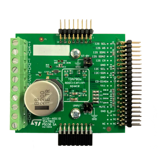
Hardware description Board description This board is based for TDA7803A and TDA7808 in PSO36 package. It is designed to provide 4 x 27 W on 4 Ω load. Figure 1. EVAL-7803APSO-SA board Top view UM2758 - Rev 1 page 2/13... -
Page 3: Figure 2. Eval-7803Apso-Sa Board Bottom View
Adequate heat dissipation must be provided for optimal performance: heatsink provided with demo board ensures optimal dissipation when device is supplied with 14 V supply and a 4 Ω load is connected to its outputs. For further information about high power measurements please contact ST application team. -
Page 4: Connector And Connections
UM2758 Connector and connections Connector and connections Power supply The power supply, ranging from 4.5 V to 18.5 V, can be connected on J4 screw terminal following the labels. Outputs The amplifier outputs are present on J1, J2, J3, J8 screw terminal. The output assigned to each connection is written nearby the connector Input control signal On J5 terminal is possible to find the I... -
Page 5: Board Schematic
UM2758 Board schematic Board schematic Figure 3. EVAL-7803APSO-SA board schematic STD DONGLE CONNECT OR DGN D OUT3 - OUT3 - OUT4 - OUT4 - SDA 1 VCC3 4 VCC3 4 SDA 1 R9 0R NM SDA 1 SDA 2 VCC3 4 VCC3 4 4.7nF NM... -
Page 6: Bill Of Materials
UM2758 Bill of materials Bill of materials Table 1. Bill of materials Quantity Designator Description Value Rated V Package SMD Electrolityc Capacitor 2200 uF 25 V 19x19 d18 mm SMD MLCC X7R Capacitor 220 nF 25 V 0603 C3, C4, C5, C6 SMD MLCC X7R Capacitor 100 nF 25 V... -
Page 7: Board Layout
UM2758 Board layout Board layout Figure 4. Assembly top Figure 5. Inner 1 UM2758 - Rev 1 page 7/13... -
Page 8: Figure 6. Inner 2
UM2758 Board layout Figure 6. inner 2 Figure 7. Assembly bottom UM2758 - Rev 1 page 8/13... -
Page 9: Information On Board Use
This evaluation board/kit is intended to be used for ENGINEERING DEVELOPMENT, DEMONSTRATION OR EVALUATION PURPOSES ONLY and it is not considered by ST Microelectronics (ST) a finished end product fit for general consumer use. People handling the product(s) must have electronics training and observe good engineering practice standards. -
Page 10: Revision History
UM2758 Revision history Table 2. Document revision history Date Version Changes 05-Aug-2020 Initial release. UM2758 - Rev 1 page 10/13... -
Page 11: Table Of Contents
UM2758 Contents Contents Hardware description ............. . 2 Board description . - Page 12 EVAL-7803APSO-SA board Bottom view ........
- Page 13 ST’s terms and conditions of sale in place at the time of order acknowledgement. Purchasers are solely responsible for the choice, selection, and use of ST products and ST assumes no liability for application assistance or the design of Purchasers’...
Need help?
Do you have a question about the EVAL-7803APSO-SA and is the answer not in the manual?
Questions and answers