Table of Contents
Advertisement
Quick Links
Introduction
This user manual describes the EVALSTPM34, EVALSTPM33, EVALSTPM32 evaluation board.
The STPM3x is an ASSP family of mixed signals designed for high accuracy measurement of power and energy in power line
systems using the Rogowski coil, current transformer or shunt current sensors. According to p/n, the device has up to two
voltages and two current channels, for energy measurement in dual-phase and single-phase (with or without neutral current
monitoring) electricity metering systems.
The STPM3x devices provide instantaneous voltage and current waveforms and calculate voltage and current RMS values,
active, reactive and apparent powers and energies for each channel. Moreover, they embed a full set of calibration and
compensation parameters which allow the meter to fit tight accuracy standards (EN 50470-x, IEC 62053-2x, ANSI12.2x for AC
watt meters). All calculated data, as well as configuration parameters, are stored in internal 32-bit registers accessible through
SPI or UART peripheral. Three boards are available for evaluation purpose:
•
EVALSTPM34 board with 2 CT
•
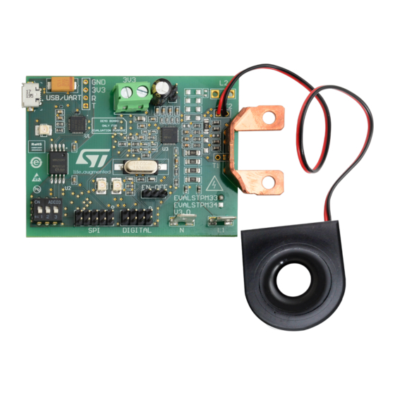
EVALSTPM33 board with CT and shunt
•
EVALSTPM32 board with shunt
The main features of these boards are:
•
0.2% accuracy single-phase meter reference design
•
USB port for connection to the isolated hardware programmer STEVAL-IPE023V1 and PC GUI
•
On-board USB isolated connection for UART data exchange to PC GUI (virtual COM port). RS-232 port for UART data
exchange (board version 1 only)
•
SPI/UART switch for device peripheral selection
•
2x programmable LEDs on-board
•
Digital expansion to external system-on-chip or MCU
•
Power supply 3.3 V: external or through the STEVAL-IPE023V1 isolated USB board
•
IEC61000 standard compliant
UM1748 - Rev 3 - March 2022
For further information contact your local STMicroelectronics sales office.
EVALSTPM34, EVALSTPM33, EVALSTPM32 evaluation board
UM1748
User manual
www.st.com
Advertisement
Table of Contents

Related Manuals for ST UM1748


Summary of Contents for ST UM1748
- Page 1 Digital expansion to external system-on-chip or MCU • Power supply 3.3 V: external or through the STEVAL-IPE023V1 isolated USB board • IEC61000 standard compliant UM1748 - Rev 3 - March 2022 www.st.com For further information contact your local STMicroelectronics sales office.
-
Page 2: Overview
UM1748 Overview Overview Figure 1. EVALSTPM34 board Figure 2. EVALSTPM33 board UM1748 - Rev 3 page 2/15... -
Page 3: Safety Rules
EVALSTPM34 schematics Getting technical support All our customers receive free technical assistance through local ST distributor/office or by visiting www.st.com; upgrades are also available free of charge on www.st.com/metering. Customers should work with the latest version of software/firmware before contacting us. -
Page 4: Evalstpm34, Evalstpm33, Evalstpm32 Board
V DC supply must be provided through J7 connector, anyway. 2.1.3 Enable and reset The STPM3x enable pin should be shorted to VCC by keeping J4 jumper in EN position. To reset the device, this jumper has to be in OFF position (GND). UM1748 - Rev 3 page 4/15... -
Page 5: Digital Output
J6 connector for 10-pin flat cable interfacing either to the STEVAL-IPE023V1 or to an external MCU. Table 4. J6 SPI connector pinout Name Description Not connected MOSI MISO Not connected Not connected The STEVAL-IPE023V1 provides isolation, while J6 pins are not isolated. UM1748 - Rev 3 page 5/15... -
Page 6: On-Board Usb (Uart) Connection
Two LEDs are connected to programmable LED pins of the device. 2.1.9 Clock Clocking is provided to the board through 16 MHz quartz. 1 MOhm resistor and 15 pF capacitors are used to filter noise. UM1748 - Rev 3 page 6/15... -
Page 7: Voltage Reference
In case of connection to the mains, this must be taken into account since, according to the wire connected to the shunt, the board GND may be either at the 0 or 230 V potential. Figure 4. Board connection to phantom load, dual-phase system (STPM34) UM1748 - Rev 3 page 7/15... -
Page 8: Figure 5. Board Connection To Phantom Load, Single-Phase System With Neutral Monitoring (Stpm34 And Stpm33)
UM1748 Connection to the line Figure 5. Board connection to phantom load, single-phase system with neutral monitoring (STPM34 and STPM33) Figure 6. Board connection to phantom load, single-phase system (STPM3x) UM1748 - Rev 3 page 8/15... -
Page 9: Board Setup
Figure 7. Board connection to isolated AC source (STPM34 and STPM33) Figure 8. Board connection to mains Board setup Regarding to the STPM3x evaluation software setup and use, please refer to user manual UM1719. UM1748 - Rev 3 page 9/15... -
Page 10: Connection To Pc Gui Through The Steval-Ipe023V1
All other parameters can be changed according to the needs (board calibration, phase-shift compensation, desired output on the programmable pin,…). For further information on the device configuration, please refer to the STPM3x datasheet. UM1748 - Rev 3 page 10/15... -
Page 11: Revision History
Changed figure titled "Board connection to phantom load, single-phase system (STPM3x)" and figure titled "Board connection to isolated AC source (STPM34 and STPM33)". Added figure titled "Board connection to mains". 31-Mar-2022 Updated to comply with ver. 1 and 3 of the evaluation boards UM1748 - Rev 3 page 11/15... -
Page 12: Table Of Contents
Disclaimer ................15 UM1748 - Rev 3... -
Page 13: List Of Tables
Document revision history ............. 11 UM1748 - Rev 3... -
Page 14: List Of Figures
Board connection to mains ............9 UM1748 - Rev 3... -
Page 15: Disclaimer
ST’s terms and conditions of sale in place at the time of order acknowledgment. Purchasers are solely responsible for the choice, selection, and use of ST products and ST assumes no liability for application assistance or the design of purchasers’...
Need help?
Do you have a question about the UM1748 and is the answer not in the manual?
Questions and answers