Table of Contents
Advertisement
Quick Links
INSTALLATION AND OPERATING MANUAL
Series
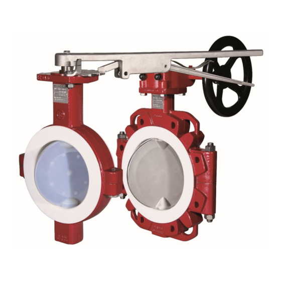
NKS/F, NKSP/F,
NKL/F, NKLP/F
Shut-off and Control Butterfly Valve
Sandwich-type body:
Lug-style body:
Keep for future use!
This operating manual must be strictly observed before
transport, installation, operation and maintenance
Subject to change without notice.
Reproduction is generally permitted with indication of the source.
© Richter Chemie-Technik GmbH.
9520-020-en Revision 16 Edition 05/2020
Series NKS/F
Series NKL/F
Advertisement
Table of Contents

Related Manuals for Richter NKS/F Series


Summary of Contents for Richter NKS/F Series
- Page 1 Keep for future use! This operating manual must be strictly observed before transport, installation, operation and maintenance Subject to change without notice. Reproduction is generally permitted with indication of the source. © Richter Chemie-Technik GmbH. 9520-020-en Revision 16 Edition 05/2020...
-
Page 2: Table Of Contents
Series NKS/F, NKSP/F, NKL/F, NKLP/F Page 2 List of Contents List of Contents ..........2 7 Operation ........... 14 Relevant documents ........3 7.1 Initial commissioning ........14 7.2 Improper operation and their consequences 1 Technical data ..........3 ..............14 1.1 Overview of sizes ........... -
Page 3: Relevant Documents
♦ Form for Safety Information Concerning the Contamination QM 0912-16-2001_en ♦ For NKSP/F NKLP/F: operating manual for actuator Technical data Manufacturer : Materials : Richter Chemie-Technik GmbH Body material: Ductile cast iron EN-JS 1049 / Otto-Schott-Str. 2 ASTM A395 D-47906 Kempen Lining material: PTFE .../F... -
Page 4: Overview Of Sizes
Series NKS/F, NKSP/F, NKL/F, NKLP/F Page 4 Overview of sizes Series actuation /F-L Body design DN 50, 80, 100, 150, 200 DN 50, 80, 100, 150, 200 lever 2", 3", 4" 6, 8" 2", 3", 4" 6, 8" NKS/F Gear DN 50, 80, 100, 150-400 DN 50, 80, 100, 150-300, Actuator... -
Page 5: Tightening Torques
Series NKS/F, NKSP/F, NKL/F, NKLP/F Page 5 Sign for transport securing device for actuator Pipe screws, flanges to ISO/DIN Flange screws Tightening torque Nominal size [mm] [ISO/DIN] [Nm] 4 x M16 8 x M16 8 x M16 8 x M20 8 x M20 12 x M20 12 x M20... -
Page 6: Dimensions
Series NKS/F, NKSP/F, NKL/F, NKLP/F Page 6 Hex. socket screw 914/1 for sandwich body Hex. socket Tightening Nominal size screw torque [mm] [inch] [ISO/DIN] [Nm] [in-lbs] 2“ 2 x M10 3“ 2 x M12 4“ 2 x M12 6“ 2 x M16 8“... -
Page 7: Weights (Ca. Kg)
Series NKS/F, NKSP/F, NKL/F, NKLP/F Page 7 Weights (ca. kg) Sandwich- Nominal size Lug style body body free free Actuated with [mm] [inch] Gear shaft end shaft end lever 2“ 3“ 4“ 6“ 16.0 11.0 8“ 23.0 15.0 10“ 35.0 25.0 12“... -
Page 8: Actuating Torques
Intended use information which is to be observed during installation, operation and maintenance. Richter shut-off and control butterfly valves are It must be read before installation and commissioning! pressure-maintaining components in accordance with This operating manual must always be available at the the German Pressure Equipment Directive (DGRL) for place of use of the valve. -
Page 9: For The Customer / Operator
Series NKS/F, NKSP/F, NKL/F, NKLP/F Page 9 Product features: ♦ the valve has been properly installed in the pipe system ♦ Wide sealing surfaces of the body lining ♦ the usual flow rates are not exceeded in continu- ♦ Long valve neck for optimum heat insulation ous operation. -
Page 10: Safety Note For Valves, Certified To Clean Air Act (Ta Luft)
Series NKS/F, NKSP/F, NKL/F, NKLP/F Page 10 ♦ If the valve is heated (e.g. heating jacket), it must Chargeable liquid and non-conductive lining be ensured that the temperature classes pre- Charges can occur on the lining surface. As a scribed in the Annex are observed. result, this can produce discharges inside and ♦... -
Page 11: Transport, Storage And Disposal
Series NKS/F, NKSP/F, NKL/F, NKLP/F Page 11 Transport, storage and disposal For all transport work, observe generally Return consignments accepted engineering practice and the accident prevention regulations. Valves which have conveyed aggressive or toxic media rinse and clean before being The valve is supplied with flange caps. -
Page 12: Disposal
Series NKS/F, NKSP/F, NKL/F, NKLP/F Page 12 Disposal ♦ Prior to the disposal of the valve: ▪ Collect any medium, etc. which has escaped and dispose of it in accordance with the local Parts of the valve may be contaminated with medium regulations. -
Page 13: Installation
10 – 15 . PTFE-lined seals with a metal inlay. These gaskets ♦ Remove the locking plate 507 before the first test are available as special accessories in the Richter actuation, screw in again hex. screw 901/1. Slightly range. -
Page 14: Operation
Series NKS/F, NKSP/F, NKL/F, NKLP/F Page 14 Operation Initial commissioning ♦ Non-observance pressure-temperature diagram can lead to damage. ♦ Do not subject the lever to heavy loads; the lever Normally, the valves have been tested for leaks with or valve may be damaged. air or water. -
Page 15: Maintenance
For detailed installation and inspection regulations for damaged and this can result in malfunc- shut-off and control butterfly valves, see QM No. tions during operation. 0910-08-1005, available from Richter on request. Notes on assembly Valve actuation ♦ The flexible inlay 521 expands during assembly. -
Page 16: Actuated By Means Of Worm Gear
Series NKS/F, NKSP/F, NKL/F, NKLP/F Page 16 9.2.2 Actuated by means of worm gear In order to ensure leak monitoring, Richter recom- mends the combination of the safety stuffing box with a warning connection. In the standard version, the manufacturer normally... -
Page 17: Drawings
Series NKS/F, NKSP/F, NKL/F, NKLP/F Page 17 Drawings 10.1 Legend shell Option safety stuffing box lever assemly disc/stem unit 402/1 Packing ring guide pin sealing foil (up to. DN 150 / 6“ inclusive) Spring gland follower plain bearing disc 400/1 O-Ring 901/3 hex. -
Page 18: Sectional Drawing Nks/F, Dn 50 - 150, 2"- 6
Series NKS/F, NKSP/F, NKL/F, NKLP/F Page 18 10.2 Sectional drawing NKS/F, DN 50 – 150, 2"– 6" Wafer-style body, with lever assembly, disc/stem unit PFA-lined * Only with option safety stuffing box. 9520-020-en Revision 16 TM 10207 Edition 05/2020... -
Page 19: Sectional Drawing Nks/F, Dn 200-400, 8"-14
Series NKS/F, NKSP/F, NKL/F, NKLP/F Page 19 10.3 Sectional drawing NKS/F, DN 200-400, 8"-14" Wafer-style body, with lever assembly, disc/stem unit PFA-lined DN 250-400, 10"-14" standard with worm gear * Only with option safety stuffing box. 9520-020-en Revision 16 TM 10207 Edition 05/2020... -
Page 20: Sectional Drawing Nkl/F, Dn 50 - 150, 2"- 6
Series NKS/F, NKSP/F, NKL/F, NKLP/F Page 20 10.4 Sectional drawing NKL/F, DN 50 – 150, 2"– 6" Lug-style body. with lever assembly, disc/stem unit PFA-lined * Only with option safety stuffing box. 9520-020-en Revision 16 TM 10207 Edition 05/2020... -
Page 21: Sectional Drawing Nkl/F, Dn 200-400, 8"-14
Series NKS/F, NKSP/F, NKL/F, NKLP/F Page 21 10.5 Sectional drawing NKL/F, DN 200-400, 8"-14" Lug-style body. with lever assembly, disc/stem unit PFA-lined DN 250-400, 10"-14" standard with worm gear * Only with option safety stuffing box. 9520-020-en Revision 16 TM 10207 Edition 05/2020... -
Page 22: Worm Gear
Series NKS/F, NKSP/F, NKL/F, NKLP/F Page 22 10.6 Worm gear 10.7 Actuator 9520-020-en Revision 16 TM 10207 Edition 05/2020... -
Page 23: Option Safety Stuffing Box
Series NKS/F, NKSP/F, NKL/F, NKLP/F Page 23 10.8 Option safety stuffing box lever assembly Actuated by means of worm gear Option monitoring connection see lever unit Actuator Option monitoring connection see lever unit 9520-020-en Revision 16 TM 10207 Edition 05/2020... -
Page 24: Dimensional Drawing Nks/F With Lever Assembly
Series NKS/F, NKSP/F, NKL/F, NKLP/F Page 24 10.9 Dimensional drawing NKS/F with lever assembly (2“) (3“) (4“) (6“) (8“) (10“) (12“) (14“) (16“) (inch) (5.31) (6.30) (6.89) (8.35) (9.13) (inch) (1.57) (1.89) (inch) (2.84) (3.50) (3.94) (5.04) (6.50) (inch) (11.81) (19.68) (inch) (1.69) -
Page 25: Dimensional Drawing Nks/F With Worm Gear
Series NKS/F, NKSP/F, NKL/F, NKLP/F Page 25 10.10 Dimensional drawing NKS/F with worm gear (2“) (3“) (4“) (6“) (8“) (10“) (12“) (14“) (16“) (inch) (5.31) (6.30) (6.89) (8.35) (9.13) (10.71) (11.69) (13.19) (14.17) (inch (1.06) (1.57) (1.65) (inch) (2.84) (3.50) (3.94) (5.04) (6.50) -
Page 26: Dimensional Drawing Nksp/F
Series NKS/F, NKSP/F, NKL/F, NKLP/F Page 26 10.11 Dimensional drawing NKSP/F 9520-020-en Revision 16 TM 10207 Edition 05/2020... - Page 27 Series NKS/F, NKSP/F, NKL/F, NKLP/F Page 27 Table NKSP/F (2“) (3“) (4“) (6“) (8“) (10“) (12“) (14“) (16“) DIN EN ISO 5211 (inch) (5.31) (6.30) (6.89) (8.35) (9.13) (10.71) (11.69) (13.19) (14.17) 60** (inch) (2.36) (3.15) (3.94) (inch) (2.84) (3.50) (3.94) (5.04) (6.50)
-
Page 28: Dimensional Drawing Nkl/F With Lever Assembly
Series NKS/F, NKSP/F, NKL/F, NKLP/F Page 28 10.12 Dimensional drawing NKL/F with lever assembly (2“) (3“) (4“) (6“) (8“) (10“) (12“) (14“) (16“) (inch) (5.31) (6.30) (6.89) (8.35) (9.13) (inch) (1.57) (1.89) (inch) (11.81) (19.68) (inch) (2.84) (3.50) (3.94) (5.04) (6.50) (inch) (1.69) -
Page 29: Dimensional Drawing Nkl/F With Worm Gear
Series NKS/F, NKSP/F, NKL/F, NKLP/F Page 29 10.13 Dimensional drawing NKL/F with worm gear (2“) (3“) (4“) (6“) (8“) (10“) (12“) (14“) (16“) (inch) (5.31) (6.30) (6.89) (8.35) (9.13) (10.71) (11.69) (13.98) (14.17) (inch) (1.06) (1.57) (1.65) (inch) (2.83) (3.50) (3.94) (5.04) (6.50) -
Page 30: Dimensional Drawing Nklp/F
Series NKS/F, NKSP/F, NKL/F, NKLP/F Page 30 10.14 Dimensional drawing NKLP/F 9520-020-en Revision 16 TM 10207 Edition 05/2020... - Page 31 Series NKS/F, NKSP/F, NKL/F, NKLP/F Page 31 Table NKLP/F (2“) (3“) (4“) (6“) (8“) (10“) (12“) (14“) (16“) ISO 5211 (inch) (5.31) (6.30) (6.89) (8.35) (9.13) (10.71) (11.69) (13.19) (14.17) 60** (inch) (2.36) (3.15) (3.94) (inch) (2.84) (3.50) (3.94) (5.04) (6.50) (7.68) (8.86)
- Page 33 PTFE Mod. PTFE Das Unternehmen Richter Chemie-Technik GmbH bescheinigt hiermit, dass in medium berührten Teilen der o.a. Baureihen Werkstoffe verwendet wurden, welche die Vorschriften der FDA Regulation 21 CFR §177.15 50, die Verordnungen 97/48/EG, EU Nr. 10/2011, EU Nr. 1935/2004, 84/500/EWG und 2005/31/EG erfüllen bzw. dafür die allgemeinen Unbedenklichkeitsbescheinigungen des Herstellers/Lieferanten vorliegen.
- Page 36 Waste Management Law (AbfG) and the Water Resources Act (WHG) An inspection/repair of Richter products and parts will only take place, if the attached explanation is filled out cor- rectly and completely by authorized and qualified technical personnel and is available.
- Page 37 Safety Information / Declaration of No Objection Concerning the Contamination of Richter-Pumps, -Valves and Components SCOPE AND PURPOSE Each entrepreneur (operator) carries the responsibility for the health and safety of his employees. This extends also to the personnel, who implements repairs with the operator or with the contractor.
- Page 38 for credit note Phone : Fax : End user : A. Details of Richter-product: Failure description: Classification: Article number: Serial number: B. Condition of the Richter- product: Contamination : Was it in operation ? toxic ...
- Page 39 Fax: + 91 / 22 / 287 94 680 Email: RichterCedarFalls-Info@idexcorp.com Email: RichterMumbai-Info@idexcorp.com Internet: www.richter-inc.com Internet: www.richter-ct.com © Richter Chemie-Technik GmbH 2020 Edition 05/2020 Subject to change without notice. Revision 0,1 9520B020-en Richter™ = Richter Chemie-Technik GmbH; IDEX™ = IDEX Corporation...
Need help?
Do you have a question about the NKS/F Series and is the answer not in the manual?
Questions and answers