Table of Contents
Advertisement
Advertisement
Table of Contents

Related Manuals for Cattani TURBO SMART HP


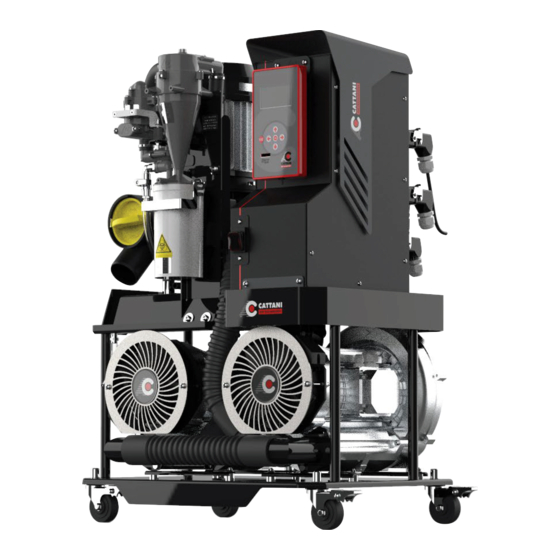
Summary of Contents for Cattani TURBO SMART HP
- Page 1 WE LOVE WHAT WE DO. TURBO SMART Instruction Manual English...
-
Page 3: Table Of Contents
CONTENTS General operation data Introduction Signals and warnings Installation and starting Routine maintenance Extraordinary maintenance Instructions for adjusting some parameters in the menus of Smart aspirators Instructions for configuration of WIFI (wireless) communication Alarms description Important warnings Transport and storage Transport of used systems Waste disposal Pictures... -
Page 4: General Operation Data
GENERAL OPERATION DATA 50/60 HZ TURBO-SMART HP SUCTION UNIT Model Turbo-Smart HP Nominal voltage 230 V Nominal frequency 50/60 Hz Absorbed power 12 A Protection level against direct and indirect Class I contacts Method of use Continuous operation Protection against humidity Standard Maximum flow rate 1916 l/min... -
Page 5: Introduction
SIGNALS AND WARNINGS INTRODUCTION The purpose of the following presentation is to www.cattani.it. We recommend you refer to these, illustrate the assembly and startup of Smart especially for the latest safety updates. suction unit and to inform users about the dangers... -
Page 6: Installation And Starting
INSTALLATION AND STARTING RECOMMENDED PRECAUTIONS Before unpacking the device, check the outside HANDLE of the packaging, check the Shockwatch impact WITH CARE WARNING WARNING indicator device, if it is red, or if the box is damaged, SHOCKWATCH accept it, subject to inspection of the device. RED INDICATES ROUGH HANDLING IF RED, NOTE ON BILL OF LADING INSPECTION MAY BE WARRANTED... - Page 7 ASSEMBLY Before connecting the suction unit to the piping of the centralized system, ensure that the suction lines are clean, heavy particles can damage the device. The suction pipe (in PVC light grey colour provided with the device) must be connected to the 50 mm diameter “suctioned fluid inlet”...
- Page 8 Even for installations where the Smart suction units are setup at a floor below the clinic, the suction piping must reach the floor where the suction unit is located, run flat along the floor for a few metres then rise with a flexible tube up to the centrifugal separator (fig.
- Page 9 PARALLEL INSTALLATION It is advisable to install in parallel only identical noticing it. To address this issue, the control unit machines, having the same flow rate and the same (see wiring diagram page 31) clamps head. Two or three suction units in parallel* double (dry contacts) carry an alarm signal at remote or triple the flow rate, provided that the diameter distance.
- Page 10 STARTING UP, TESTING AND INSTRUCTING PERSONNEL Once the suction unit is installed and connected to the power supply, simply press the on/off button and close the suction contact (send the permissive signal) from one of the dental units connected to start the suction.
- Page 11 ISO AMALGAM SEPARATOR The Turbo-Smart HP can be ordered complete with the “Hydrocyclon ISO 18” amalgam separator. The amalgam separator always comes with the operation and maintenance manual. cod: ed. 09-2021...
-
Page 12: Routine Maintenance
ROUTINE MAINTENANCE ROUTINE MAINTENANCE Ordinary maintenance to be carried out by trained members of the dental clinic. • Please be aware of all hazard signs and protect yourself with glasses, gloves and disposable overalls. DAYLY • Check the display for possible alarms, if danger •... -
Page 13: Extraordinary Maintenance
EXTRAORDINARY MAINTENANCE EXTRAORDINARY MAINTENANCE Extraordinary maintenance is to be carried out by a trained technician, using original spare parts: • Be aware of hazard signs and wear protective glasses, gloves and disposable overalls. • Check maintenance condition, ensure that Magnolia products are being used. - Page 14 RECOMMENDED INSPECTIONS EVERY 18-24 MONTHS • Check efficiency of centrifugal separator (11) and of the recirculation valve (14). RECOMMENDED INSPECTIONS EVERY 10,000 HOURS • Rubber parts: O Rings, bellows, seals must be replaced every time a part that affects seal is disassembled.
-
Page 15: Instructions For Adjusting Some Parameters In The Menus Of Smart Aspirators
PARAMETERS IN THE MENUS OF SMART ASPIRATORS MAIN MENU When the control unit is switched on, the graphic display shows the Cattani S.p.A. logo for 10 seconds, then the main menu appears. MAIN MENU “A1” The display shows parameters such as operating frequency, time for suction unit activation, temperature, amalgam container (if any) and system software version. - Page 16 CONTROL MENU “A2” Counters – Odom . A2 Power Cycles 00000 Number of switch-on from master switch Uptime [h] 00000 Total switch-on hours (with motors off) Work Cycles 00000 Number of activations by suction control Work Time [h] 00000 Actual operation hours (motors on) Aspirator [h] 00000 Hours operation in relation to frequency Fan Cycles...
- Page 17 This is where you can adjust switch-off delay and other technical parameters. FACTORY SETTINGS RESTRICTED ACCESS This menu is not accessible, exclusively reserved to Cattani company. WI FI SETTINGS This menu can be accessed without a password and it is used to configure the Wi-Fi parameters.
- Page 18 “Password” and the cursor will disappear. Press to go back to the menu “Cattani S.p.A.”. Now you can change the parameters of the “User Parameters” menu. Repeat the same procedure to enter the password 0000456000 and access the changes of the “System Parameters Setup”...
- Page 19 Centrifugal separator current System temperature Maximum temperature detected (can be reset with code 19404 in menu drive commands) Maximum detected temperature Bus voltage Maximum bus voltage recorded Ripple bus voltage cod: ed. 09-2021...
- Page 20 0 or 1 or 2 or 3 or 4 or 5. Press Enter to confirm change Generated code This code is generated by Cattani S.p.A.. Each machine has a unique code. Activation code - if any cod: ed. 09-2021...
- Page 21 “SYSTEM PARAMETERS SETUP” MENU To access this menu, enter Access Password 0000456000 (see instructions on p.21). Now you can change some of the settings. To change the parameters in this menu: Scroll the menu with the arrows to highlight the parameters you want to change.
- Page 22 Blower current limit for the medium vacuum level (not active) Surgical vacuum level (not active) Maximum blower frequency for surgical vacuum level (not active) Blower current limit for surgical vacuum level (not active) Switch-off delay (max. 300 S) Pump switch-off delay (max. 7200 S) Fan switch-off delay (max.
- Page 23 Options Used Enables or disables reading of amalgam sensor. 0- without amalgam separator 1- with amalgam separator Commands to inverter. Reserved for factory settings cod: ed. 09-2021...
-
Page 24: Instructions For Configuration Of Wifi (Wireless) Communication
INSTRUCTIONS FOR CONFIGURATION OF WIFI (WIRELESS) COMMUNICATION Turbo-Smart HP can be controlled by the professional user through the SmartApp. SETTING UP CONNECTION AND COMMUNICATION ON THE SUCTION UNIT When power is switched on, the display will show this image. Menu ”A1” WI-FI OFF Press to Menu “A4”... - Page 25 From the M0 Menu, using the continue up to arrows Menu WI-FI M5 To access the Menu press Now, the WI-FI menu shows in S0 the non-changeable IP address (dynamic IP). In the WI-FI menu to control the selected network n SSID M5 S1 In Menu M5-S2, use the arrows to key in and enter the WI-FI router password.
- Page 26 Make sure that DHCP is set to 1. Make sure that M5-S5 is set to 2. Now, press the left arrow and then ESC to back to Main menu A1, where you can see WI-FI ON. When communication with a PC is on, the display will show WI-FI DATA.
-
Page 27: Alarms Description
ALARMS DESCRIPTION Alarm codes Description Solution Microcontroller memory alarm Contact technician Microcontroller memory alarm Contact technician Short circuit caused by one of the two Check cause of short circuit and remove motors Contact the technician (board probably Short circuit before motor control damaged) Failed capacitor charging Contact technician (replace the board) -
Page 28: Important Warnings
• At the www.cattani.it website you can find our • The warranty and manufacturer’s liability shall latest updated manuals. We recommend you refer cease to apply if the equipment is serviced with to these especially for the latest safety updates. -
Page 29: Waste Disposal
WASTE DISPOSAL INFORMATION FOR PROFESSIONAL USERS • Pursuant to art 13 law decree no.151 of 25 July, environment-friendly compatible disposal, No. 151 “Implementation of directive 2011/65 UE contributes to prevent possible negative effects ROHS and 2003/108/CE on restrictions on the use on the environment and on health and favours the of hazardous substances in electrical and electronic reuse and/or recycling of the materials with which... -
Page 30: Pictures
ASSEMBLY SCHEME SAME LEVEL INSTALLATION LEVEL BELOW INSTALLATION cod: ed. 09-2021... - Page 31 ELECTRICAL CONNECTIONS TURBO-SMART HP CIRCUIT Fig. C cod: ed. 09-2021...
- Page 32 TURBO-SMART HP DIAGNOSTIC TEST To verify the correct operation of a variable With the machine switched on and suction inlet frequency suction unit, some dynamic type tests not connected to the piping. The other test shall be can be carried out, such as the following. carried out with the suction inlet closed.
- Page 33 EXAMPLES OF PIPING Fig. E E = TURBO-SMART HP Fig. F cod: ed. 09-2021...
- Page 34 TURBO-SMART HP EXPLODED VIEW Fig. G cod: ed. 09-2021...
- Page 35 CENTRIFUGAL SEPARATOR 023764 EXPLODED VIEW Fig. H cod: ed. 09-2021...
- Page 36 UNI-JET 75 (SX) 015663 EXPLODED VIEW Fig. I cod: ed. 09-2021...
- Page 37 UNI-JET 75 (DX) 015664 EXPLODED VIEW Fig. L cod: ed. 09-2021...
- Page 38 AMALGAM SEPARATOR 043396 EXPLODED VIEW Fig. M cod: ed. 09-2021...
- Page 39 CONTROL UNIT 023764 EXPLODED VIEW Fig. N cod: ed. 09-2021...
- Page 40 TURBO-SMART HP DIMENSIONS Fig. O cod: ed. 09-2021...
- Page 41 TURBO-SMART HP DIMENSIONS Fig. P cod: ed. 09-2021...
- Page 42 TURBO-SMART HP DIMENSIONS Fig. Q cod: ed. 09-2021...
- Page 43 cod: ed. 09-2021...
- Page 44 We reduce costs: less maintenance and lower energy costs mean that we are always the most economical on a cost-benefit analysis. We reduce environmental impact: we save 50% on raw materials, and allow you to save between 30% and 50% on electrical consumption. Via Natta 6/A 43122 Parma – Italy T +39 0521 607 604 info@cattani.it WWW.CATTANI.IT...
Need help?
Do you have a question about the TURBO SMART HP and is the answer not in the manual?
Questions and answers