Table of Contents
Advertisement
Quick Links
Advertisement
Table of Contents

Subscribe to Our Youtube Channel
Related Manuals for Rohde & Schwarz SGT100A


Summary of Contents for Rohde & Schwarz SGT100A
- Page 1 ® R&S SGT100A SGMA Vector RF Source Getting Started (>C]Ú2) 1419457602 Version 10...
- Page 2 ® This manual describes R&S SGT100A, stock no. 1419.4501.02 and its options. © 2022 Rohde & Schwarz GmbH & Co. KG Muehldorfstr. 15, 81671 Muenchen, Germany Phone: +49 89 41 29 - 0 Email: info@rohde-schwarz.com Internet: www.rohde-schwarz.com Subject to change – data without tolerance limits is not binding.
-
Page 3: Table Of Contents
® Contents R&S SGT100A Contents 1 Safety and regulatory information........5 1.1 Safety instructions................5 1.2 Labels on R&S SGT................8 1.3 Warning messages in the documentation.......... 8 1.4 Korea certification class A..............9 2 Key features................. 10 3 Documentation overview............ 11 3.1 Getting started manual............... - Page 4 ® Contents R&S SGT100A 4.9 Connecting to non-screwable connectors........21 4.10 Switching on or off................21 4.11 Checking default settings..............24 4.12 Working with Linux operating system..........24 4.13 Connecting an external PC and devices...........25 5 Instrument tour..............33 5.1 Front panel tour.................. 33 5.2 Rear panel tour..................35...
-
Page 5: Safety And Regulatory Information
® Safety and regulatory information R&S SGT100A Safety instructions Safety and regulatory information The product documentation helps you use the product safely and efficiently. Fol- low the instructions provided here and in the following chapters. Intended use The product is intended for the development, production and verification of elec- tronic components and devices in industrial, administrative, and laboratory envi- ronments. - Page 6 ® Safety and regulatory information R&S SGT100A Safety instructions Never open the casing of the product. Only service personnel authorized by Rohde & Schwarz are allowed to repair the product. If any part of the product is damaged or broken, stop using the product. Contact Rohde & Schwarz customer service at http://www.customersupport.rohde-schwarz.com.
- Page 7 ® Safety and regulatory information R&S SGT100A Safety instructions Connecting to power The product is an overvoltage category II product. Connect the product to a fixed installation used to supply energy-consuming equipment such as household appliances and similar loads. Keep in mind that electrically powered products have risks, such as electric shock, fire, personal injury or even death.
-
Page 8: Labels On R&S Sgt
® Safety and regulatory information R&S SGT100A Warning messages in the documentation Potential hazard Read the product documentation to avoid personal injury or product damage. Electrical hazard Indicates live parts. Risk of electric shock, fire, personal injury or even death. -
Page 9: Korea Certification Class A
® Safety and regulatory information R&S SGT100A Korea certification class A CAUTION Potentially hazardous situation. Could result in minor or moderate injury if not avoided. NOTICE Potential risks of damage. Could result in damage to the supported product or to other property. -
Page 10: Key Features
® Key features R&S SGT100A Key features The key features of the R&S SGT include the following: ● Compact size and low power consumption ● Remote connection via PCI Express, minimizing the setup time Alternatively, LAN or USB connections available ●... -
Page 11: Documentation Overview
® Documentation overview R&S SGT100A User manual and help Documentation overview This section provides an overview of the R&S SGT user documentation. Unless specified otherwise, you find the documents on the R&S SGT product page at: www.rohde-schwarz.com/manual/sgt100a Getting started manual Introduces the R&S SGT and describes how to set up and start working with the... -
Page 12: Service Manual
® Documentation overview R&S SGT100A Data sheets and brochures Service manual Describes the performance test for checking the rated specifications, module replacement and repair, firmware update, troubleshooting and fault elimination, and contains mechanical drawings and spare part lists. The service manual is available for registered users on the global Rohde &... -
Page 13: Release Notes And Open Source Acknowledgment (Osa)
The open source acknowledgment document provides verbatim license texts of the used open source software. www.rohde-schwarz.com/firmware/sgt100a Application notes, application cards, white papers, etc. These documents deal with special applications or background information on particular topics. See www.rohde-schwarz.com/application/sgt100a. Getting Started 1419.4576.02 ─ 10... -
Page 14: Preparing For Use
® Preparing for use R&S SGT100A Choosing the operating site Preparing for use Here, you can find basic information about setting up the product for the first time. Lifting and carrying See also "Lifting and carrying the product" on page 6. -
Page 15: Setting Up The R&S Sgt
® Preparing for use R&S SGT100A Setting up the R&S SGT Electromagnetic compatibility classes The electromagnetic compatibility (EMC) class indicates where you can operate the product. The EMC class of the product is given in the data sheet. ● Class B equipment is suitable for use in: –... - Page 16 ® Preparing for use R&S SGT100A Setting up the R&S SGT ● Do not exceed the permissible total load placed on the product at the bot- tom of the stack: – 50 kg when stacking products of identical dimensions (left figure).
-
Page 17: Considerations For Test Setup
® Preparing for use R&S SGT100A Considerations for test setup b) Mount the adapter kit. Follow the assembly instructions provided with the adapter kit. 2. Push the R&S SGT onto the shelf until the rack brackets fit closely to the rack. -
Page 18: Connecting To Power
® Preparing for use R&S SGT100A Connecting to power ● Use the cable R&S SMU-Z6 for connection to the "DIG I/Q" interface of the instrument. The cable is available under material number 1415.0201.02. Signal input and output levels Information on signal levels is provided in the data sheet. Keep the signal levels within the specified ranges to avoid damage to the R&S SGT and connected devi-... -
Page 19: Connecting To Lan
® Preparing for use R&S SGT100A Connecting to RF 50Ω Connecting to LAN Network environment Before connecting the product to a local area network (LAN), consider the follow- ing: ● Install the latest firmware to reduce security risks. ● For internet or remote access, use secured connections if applicable. - Page 20 ® Preparing for use R&S SGT100A Connecting to RF 50Ω 2. NOTICE! Risk of instrument damage. Excessive reverse power or DC voltage at the RF 50Ω connector can damage the instrument. Make sure that the values do not exceed the reverse power and DC limits as given in the data sheet.
-
Page 21: Connecting To Non-Screwable Connectors
® Preparing for use R&S SGT100A Switching on or off To prevent RF output switch-off ► NOTICE! If you set a too high output level without a load connected to the instrument, the reverse power can exceed a limit forcing the R&S SGT to switch off the RF output. - Page 22 ® Preparing for use R&S SGT100A Switching on or off The LED of the [POWER ON/STANDBY] key is orange. 2. If equipped with an oven-controlled oscillator (OCXO), option R&S SGT-B1, wait until the OCXO warms up. For the warm-up time, see data sheet.
- Page 23 ® Preparing for use R&S SGT100A Switching on or off To start up and boot The instrument boots the operating system and starts the instrument firmware. During the booting process, the green [POWER ON/STANDBY] key blinks. If the previous session was terminated regularly, the instrument uses the last setup with the relevant instrument settings.
-
Page 24: Checking Default Settings
® Preparing for use R&S SGT100A Working with Linux operating system 4.11 Checking default settings When the instrument is switched on, it is not the preset state that is active, but rather the instrument state that was set before the instrument was switched off. It is recommended that you use the "SGMA-GUI >... -
Page 25: Connecting An External Pc And Devices
® Preparing for use R&S SGT100A Connecting an external PC and devices 4.13 Connecting an external PC and devices For control and operation, the R&S SGT requires a connection to an external device. The external device, e.g. an external PC, controls the R&S SGT via remote control or manual operation via the R&S SGMA-GUI software installed on... - Page 26 ® Preparing for use R&S SGT100A Connecting an external PC and devices within the file name (<version_number>=v.vv.vvv.vv) varies with each update. To install the R&S SGMA-GUI, check that you PC and drivers fulfill the following hardware and software requirements. Table 4-3: Hardware and software requirements...
- Page 27 ® Preparing for use R&S SGT100A Connecting an external PC and devices Start the version that is required for your application. Uninstalling an old software version You can uninstall a previous version of the software before the installing a new software version, but this step is not mandatory.
- Page 28 ® Preparing for use R&S SGT100A Connecting an external PC and devices ● A non-dedicated network (Ethernet) connection from the instrument to an existing network. ● A dedicated network connection (Point-to-point connection) between the instrument and a single computer. In both cases, an IP address has to be assigned to the instrument and the com- puter, see Chapter 4.13.2.2, "Assigning the IP...
- Page 29 ® Preparing for use R&S SGT100A Connecting an external PC and devices 4.13.2.2 Assigning the IP address Depending on the network capacities, the TCP/IP address information for the instrument can be obtained in different ways. ● If the network supports dynamic TCP/IP configuration using the Dynamic Host Configuration Protocol (DHCP), all address information can be assigned auto- matically.
- Page 30 ® Preparing for use R&S SGT100A Connecting an external PC and devices and WINS servers on your network. If you use more than one LAN connector, you need separate address information for each connector. 2. Press the "Windows" key to access the operating system.
- Page 31 ® Preparing for use R&S SGT100A Connecting an external PC and devices Note: This step is performed automatically on the first start and can also be omitted for instruments with a direct LAN connection to the computer. All instruments are added automatically to the main panel of the SIGMA-GUI.
- Page 32 ® Preparing for use R&S SGT100A Connecting an external PC and devices Prerequisite: the computer and the R&S SGT are turned on and running. 1. Start the R&S SGMA-GUI. 2. Connect the computer and the R&S SGT with a USB cable.
-
Page 33: Instrument Tour
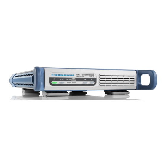
® Instrument tour R&S SGT100A Front panel tour Instrument tour This chapter explains the control elements and the connectors of the R&S SGT. The views of the front panel and the rear panel help you to get familiar with the instrument and to perform first steps. - Page 34 ® Instrument tour R&S SGT100A Front panel tour ● "To switch between standby and ready state" on page 22 [RF ON] The [RF ON] key switches the RF signal on or off. If activated, the key is green. Table 5-1: Overview of RF signal states...
-
Page 35: Rear Panel Tour
® Instrument tour R&S SGT100A Rear panel tour Pressing the [LAN] key resets the network settings, e.g., "IP Adress Mode" is reset to "DHCP". Table 5-4: Overview of LAN connection states [LAN] state Remark Connected Connected to the network. green... - Page 36 ® Instrument tour R&S SGT100A Rear panel tour Figure 5-2: R&S SGT rear panel controls and connectors AC power supply connector and power switch I/Q, I/Q Bar PCIe USB IN DIG I/Q 7, 10 = USER 1/2 RF 50Ω LO IN, LO OUT, REF IN, REF OUT...
- Page 37 ® Instrument tour R&S SGT100A Rear panel tour USB IN USB (universal serial bus) type Micro-B connector for remote control via various external devices. How to: Chapter 4.13.4, "Connecting a controller via USB", on page 31 DIG I/Q Connector for the input of a digital I/Q signal from a Rohde & Schwarz instrument, like a signal generator.
-
Page 38: Connector Extension Unit (R&S Sgt-B88)
® Instrument tour R&S SGT100A Connector extension unit (R&S SGT-B88) Connector extension unit (R&S SGT-B88) This chapter provides an overview of control elements and connectors of the R&S SGT connector extension unit. Order the R&S SGT connector extension unit R&S SGT-B88 together with a new R&S SGT instrument. - Page 39 ® Instrument tour R&S SGT100A Connector extension unit (R&S SGT-B88) 5.3.2 Rear panel This section provides an overview of the connectors on the rear panel of the extension unit. For an overview of the connectors of the rear panel of R&S SGT, refer to Chap- ter 5.2, "Rear panel...
- Page 40 ® Instrument tour R&S SGT100A Connector extension unit (R&S SGT-B88) Also, use the connector for input of external pulse modulator signal. How to: Chapter 4.9, "Connecting to non-screwable connectors", on page 21 BNC connectors for input of an external I/Q modulator. The signal is fed directly into the I/Q modulator.
-
Page 41: Trying Out The Instrument
® Trying out the instrument R&S SGT100A Trying out the instrument This chapter introduces the most important functions and settings of the R&S SGT step by step. The complete description of the functionality and its usage is given in the R&S SGT user manual. -
Page 42: How To Generate A Cw Signal
® Trying out the instrument R&S SGT100A How to generate a CW signal How to generate a CW signal Configuring the R&S SGT to generate a CW signal Figure 6-1: Example of the setup 1. Check, that [POWER ON/STANDBY] key is green. -
Page 43: How To Create And Load A Waveform File
® Trying out the instrument R&S SGT100A How to create and load a waveform file 6. In the R&S SGMA-GUI main panel, select the row of the instrument that you want to configure. 7. Set the "Frequency" as required. 8. Select "SGMA-GUI > RF On" to enable the output of the CW signal. - Page 44 ® Trying out the instrument R&S SGT100A How to create and load a waveform file The workflow consists of three main steps, each described in a separate step-by- step instruction: ● Configuring the connection between the R&S WinIQSIM2 and the R&S SGT.
- Page 45 ® Trying out the instrument R&S SGT100A How to create and load a waveform file The software scans the network for connected and active instruments. Alternatively, use the "New" function to add the R&S SGT manually to the list of instruments.
- Page 46 ® Trying out the instrument R&S SGT100A How to create and load a waveform file The two lines to the "Vector Sig Gen" and "Arb Sig Gen" blocks on the block diagram confirm that a remote connection to the R&S SGT is established.
- Page 47 ® Trying out the instrument R&S SGT100A How to create and load a waveform file The R&S WinIQSIM2 calculates the signal and displays important signal parameters, like the used "Sample Rate" and "Number of Samples". Getting Started 1419.4576.02 ─ 10...
- Page 48 ® Trying out the instrument R&S SGT100A How to create and load a waveform file Use "Graphics > Graphic 1" view to retrieve more information on the gener- ated signal. The display confirms the expected EUTRA/LTE 10 MHz spectrum. To transfer the generated file to the R&S SGT 1.
- Page 49 ® Trying out the instrument R&S SGT100A How to create and load a waveform file The waveform is transmitted to the default directory of the R&S SGT. 3. In the R&S SGT, select "Baseband > ARB". The dialog confirms that the ARB is enabled and plays the transmitted wave- form.
-
Page 50: Instrument Control
® Instrument control R&S SGT100A Manual operation via R&S SGMA-GUI Instrument control As a rule, the R&S SGT is operated exclusively via programmatic remote control from a connected PC. For service and diagnostic tasks, and for manual configura- tion, a graphical user interface (R&S SGMA-GUI) is provided which runs on the remote PC. - Page 51 ® Instrument control R&S SGT100A Manual operation via R&S SGMA-GUI The main dialog with an overview of the configured instruments is the operating and control interface for the whole program. From here, all program functions are accessible. The menus and dialogs are built using elements like selection lists, check boxes, and entry fields.
- Page 52 ® Instrument control R&S SGT100A Manual operation via R&S SGMA-GUI Calling context-sensitive and general help ► To display the general help dialog box, select the "SGMA-GUI > Help > Con- tents" or use the F1 key. The help dialog is displayed. A topic containing information about the current menu or the currently opened dialog box and its function is displayed.
-
Page 53: Network Operation And Remote Control
® Instrument control R&S SGT100A Network operation and remote control 5. Use the "Scroll Right" or "Scroll Left" buttons to shift the indicated area of the navigation window to the left or right. Using the index 1. Select "SGMA-GUI > Help > Index" or use the "Go to Index" button in the "Help"... - Page 54 ® Instrument control R&S SGT100A Network operation and remote control Table 7-1: Remote control interfaces and protocols Interface Protocols Remarks ● Local A LAN connector is located on the HiSLIP High-Speed LAN Instrument Proto- Area Net- rear panel of the instrument.
- Page 55 ® Instrument control R&S SGT100A Network operation and remote control 5). The TCP/IP network protocol and the associated network services are precon- figured on the instrument. Software for instrument control and (for specified proto- cols only) the VISA program library must be installed on the controller.
- Page 56 ® Instrument control R&S SGT100A Network operation and remote control hislip0 is composed of [::HiSLIP device name[,HiSLIP port]] and must be assigned. For details of the HiSLIP protocol, refer to "HiSLIP protocol" on page 56. VXI-11 TCPIP::host address[::inst0][::INSTR] ● [::inst0] LAN device name, indicates that the VXI-11 protocol is used (optional).
- Page 57 ® Instrument control R&S SGT100A Network operation and remote control uses two TCP sockets for a single connection - one for fast data transfer, the other for non-sequential control commands (e.g. Device Clear or SRQ). HiSLIP has the following characteristics: ●...
- Page 58 ® Instrument control R&S SGT100A Network operation and remote control The simplest way to establish socket communication is to use the built-in telnet program. The telnet program is part of every operating system and supports com- munication with the software on a command-by-command basis.
- Page 59 ® Instrument control R&S SGT100A Network operation and remote control Example: PCIe::0x162f::0x1336::100021::INSTR 0x162f is the vendor ID for Rohde & Schwarz. 0x1336 is the product ID for the R&S SGT. 100021 is the serial number of the particular instrument. Using the PCIe interface for remote control of the instrument requires exten- ded knowledge and is described in section "Advanced Remote Control via...
- Page 60 ® Instrument control R&S SGT100A Network operation and remote control basic operations and attributes for a device, such as reading, writing, or trigger- ing. Any connected IEC bus cable must be terminated by an instrument or con- troller. 7.2.2 Remote control over LAN using VXI-11 protocol In the following example, the program "Measurement &...
- Page 61 ® Instrument control R&S SGT100A Network operation and remote control To configure the controller The instrument is preconfigured for networks using DHCP (dynamic host configuration protocol). If you use this configuration, enter the computer name in the position of the IP address.
- Page 62 ® Instrument control R&S SGT100A Network operation and remote control 6. Enter the IP address or the host name of the R&S SGT. 7. Select "Next". 8. Enter the alias name, if necessary. Do not mistake the alias name with the computer name. Only use the alias name for instrument identification within the program.
- Page 63 ® Instrument control R&S SGT100A Network operation and remote control 3. In the "viWrite" tab, write the command to be sent to the instrument and select "Execute". Instrument responses are displayed on the "viRead" tab. Tip: For further program operation, refer to the online help of the program.
-
Page 64: Contacting Customer Support
® Contacting customer support R&S SGT100A Contacting customer support Technical support – where and when you need it For quick, expert help with any Rohde & Schwarz product, contact our customer support center. A team of highly qualified engineers provides support and works with you to find a solution to your query on any aspect of the operation, program- ming or applications of Rohde &... -
Page 65: Index
® Index R&S SGT100A Index AC power supply Error Connector ........... 36 Key ............34 Application cards ........13 External controller ........25 Application notes ........13 External devices ........25 Bench top, placing ........15 Functional checks ........22 Brochures ..........12 Getting started ......... - Page 66 ® Index R&S SGT100A Interfaces GPIB ........... 59 PCIe USB ............ 58 Connecting ..........31 IP address ..........55 Connector ........... 36 Changing ..........29 Placing, on a bench top ......15 Power Connecting the instrument ....18 POWER ON/STANDBY ID ............35 Key ............33...
- Page 67 ® Index R&S SGT100A Unpacking the instrument ......14 Updating R&S SGMA-GUI ...... 25 Connecting ..........31 Interfaces ..........58 USB IN Connector ........... 37 USER 1/2 Connector ........... 37 User manual ..........11 VISA ............53 Resource string ........55 VXI protocol ..........57 VXI-11 ............53...
Need help?
Do you have a question about the SGT100A and is the answer not in the manual?
Questions and answers