Table of Contents
Advertisement
Quick Links
Advertisement
Table of Contents

Related Manuals for Woodward SPM-D11


Summary of Contents for Woodward SPM-D11
- Page 1 37259C SPM-D11 Synchronizing Unit Manual Software version 6.3xx Manual 37259C...
- Page 2 "i" symbol. Most of the referenced sections are included in the Annex. Woodward Governor Company reserves the right to update any portion of this publication at any time. Information provided by Wood- ward Governor Company is believed to be correct and reliable. However, Woodward Governor Company assumes no responsibility unless otherwise expressly undertaken.
-
Page 3: Table Of Contents
Manual 37259C SPM-D11 - Synchronizing Unit Revision History Rev. Date Editor Change 04-08-04 LSR/LSXR update 04-10-19 1/3-phase measurement functionality updated; linguistic update Contents 1. G ..................6 HAPTER ENERAL NFORMATION 2. E .............7 HAPTER LECTROSTATIC ISCHARGE WARENESS 3. I .......................8 HAPTER NSTALLATION Wiring Diagram ............................9... - Page 4 Manual 37259C SPM-D11 - Synchronizing Unit 5. D ..............32 HAPTER ISPLAY AND PERATING LEMENTS Brief Explanation of the LEDs and Push Buttons ................. 33 LEDs............................33 Buttons ............................33 Others............................33 LEDs ..............................34 Push Buttons ............................36 LC Display ............................37 Display Monitoring in Automatic Mode: Double Voltage / Frequency Display......
- Page 5 Figure 3-13: Controller - SPM-D11/LSR – three-position controller ..................17 Figure 3-14: Controller - SPM-D11/LSXR - Three-step controller ..................18 Figure 3-15: Controller - SPM-D11/LSXR - Analog controller output - Speed/frequency/real power ........19 Figure 3-16: Controller - SPM-D11/LSXR - Analog controller output - Voltage/power factor ..........19 Figure 4-1: Control loop ................................
-
Page 6: Chapter 1. General Information
Chapter 1. General Information The SPM-D11 is a synchronizing unit with integrated control functions for generator power levels and load shar- ing. Through the application of appropriate logic to the discrete inputs the following functions can be realized: • Synchronization, •... -
Page 7: Chapter 2. Electrostatic Discharge Awareness
WARNING To prevent damage to electronic components caused by improper handling, read and observe the pre- cautions in Woodward manual 82715, Guide for Handling and Protection of Electronic Controls, Printed Circuit Boards, and Modules. © Woodward Page 7/79... -
Page 8: Chapter 3. Installation
Manual 37259C SPM-D11 - Synchronizing Unit Chapter 3. Installation WARNING A circuit breaker must be located near to the control and in a position easily accessible to the operator. This must also bear a sign identifying it as an isolating switch for the control. -
Page 9: Wiring Diagram
Release isolated operation / dead bus - Power supply + Power supply (refer to label for actual rating V Reference point (terminal 29/30) Subject to technical modifications. 2004-10-14 | SPM-D11 Wiring Diagram spmd11ww-4204-ap.skf Figure 3-1: Wiring diagram SPM-D11/LSR © Woodward Page 9/79... -
Page 10: Spm-D11/Lsxr
Release isolated operation / dead bus - Power supply + Power supply (refer to label for actual rating V Reference point (terminal 29/30) Subject to technical modifications. 2004-10-14 | SPM-D11 Wiring Diagram spmd11ww-4204-ap.skf Figure 3-2: Wiring diagram SPM-D11/LSXR Page 10/79 © Woodward... -
Page 11: Reference Point
Manual 37259C SPM-D11 - Synchronizing Unit Reference Point ≡≡≡≡≡≡≡≡≡≡≡≡≡≡≡≡≡≡≡≡≡≡≡≡≡ Reference point Figure 3-3: Reference point Terminal Description Reference point: Neutral point of the three-phase system or neutral terminal of the voltage transformer (Measuring reference point); Sold.lug with three-conductor (delta) systems, do not connect Power Supply ≡≡≡≡≡≡≡≡≡≡≡≡≡≡≡≡≡≡≡≡≡≡≡≡≡... -
Page 12: Measuring Inputs
Connection to medium voltage via single- phase isolated transformer (e. g. Y-connection). The SPM-D11 may be connected to L1/L2 or L1/N. Regardless of what connection is used, the genera- tor and mains/busbar must always be connected identically. Correct measured values can be achieved for three-phase and single-phase systems if the SPM-D11 is configured accordingly (refer to CTs (Cur- rent Transformer) on page 42). -
Page 13: Current
If the generator load is always symmetrically, the current may also be measured in L2 or L3. This must be considered when configuring the SPM-D11 (refer to CTs (Current Transformer) on page 42). If there is a possibility that the load may be asymmetrical, the current must be measured in L1. -
Page 14: Discrete Inputs
Manual 37259C SPM-D11 - Synchronizing Unit Discrete Inputs ≡≡≡≡≡≡≡≡≡≡≡≡≡≡≡≡≡≡≡≡≡≡≡≡≡ WARNING There are two versions of this unit with different discrete inputs. The discrete inputs have different maximum voltage ratings. Look at the DATA PLATE of the unit to determine the correct voltage input ratings. -
Page 15: Analog Inputs
All controls that are load sharing must be interconnected via terminal 29 (terminals 30 must also be intercon- nected for var sharing). If an SPM-D11 is switched off, the load/var sharing line must be disconnected to prevent the disabled SPM-D11 from influencing the other controls. -
Page 16: Relay Outputs
Manual 37259C SPM-D11 - Synchronizing Unit Relay Outputs ≡≡≡≡≡≡≡≡≡≡≡≡≡≡≡≡≡≡≡≡≡≡≡≡≡ max. 250 V AC Relay output external device Figure 3-11: Relay outputs – control outputs I (CB control) Root Switched Description Synchronizing pulse, Command: close CB 2.5 mm² Command: open CB for shutdown 2.5 mm²... -
Page 17: Controller Outputs
The SPM-D11/LSR is equipped with two three-position controllers for voltage and frequency (each comprising a form C and form A relay). The SPM-D11/LSXR permits various analog or PWM output signals to be selected by configuration, which can then be utilized in different ways. -
Page 18: Spm-D11/Lsxr
Manual 37259C SPM-D11 - Synchronizing Unit SPM-D11/LSXR The SPM-D11/LSXR has various controller outputs with the following types of signal, which can be changed by configuration as well as an external bridge/jumper. Versions - Three-step controller via the relay manager - Controlling n/f: Parameter "... -
Page 19: Figure 3-15: Controller - Spm-D11/Lsxr - Analog Controller Output - Speed/Frequency/Real Power
Setting: 'ANALOG' and 'PWM' (Analog Controller) Frequency/real power controller Speed / power controller Speed / power controller Speed / power controller Figure 3-15: Controller - SPM-D11/LSXR - Analog controller output - Speed/frequency/real power Type Terminal Description 2.5 mm² 2.5 mm² Current 2.5 mm²... -
Page 20: Chapter 4. Description Of Functions
Manual 37259C SPM-D11 - Synchronizing Unit Chapter 4. Description of Functions Functional Description ≡≡≡≡≡≡≡≡≡≡≡≡≡≡≡≡≡≡≡≡≡≡≡≡≡ Table for Terminal 6 = "Enable Control" With this setting, the control can be used as an SPM-A. The status of the discrete inputs "Reply: CB is open" and "Enable CB" is displayed via the LEDs "Gen CB - ON"... -
Page 21: Table 4-2: Operating Conditions - Terminal 6 = "Off
Manual 37259C SPM-D11 - Synchronizing Unit Table for Terminal 6 = "Enable Power Set point Value 2" The status of the digital inputs "Reply: CB is open" and "Enable CB" is displayed via the LEDs "GCB closed" and "Release GCB" on the pressure-sensitive front membrane. Additional to the input signals the conditions listed in Table 4-3: Operating conditions - must be observed. -
Page 22: Additional Conditions
Manual 37259C SPM-D11 - Synchronizing Unit Additional Conditions The function of the control is also dependent, apart from the digital input signals, on the state of the available measured voltages. The particular function must also be enabled in configuration mode:... -
Page 23: Control Inputs
Manual 37259C SPM-D11 - Synchronizing Unit Control Inputs ≡≡≡≡≡≡≡≡≡≡≡≡≡≡≡≡≡≡≡≡≡≡≡≡≡ • Terminal 6 = "Release control" Release CB Terminal 3 A signal into this discrete input enables operation of the power circuit breaker. For tests during commissioning, ensuring that no voltage is ap- plied to this input will prevent the power circuit breaker from operating, even if the control functions are enabled. -
Page 24: Operating Modes
Manual 37259C SPM-D11 - Synchronizing Unit Operating Modes ≡≡≡≡≡≡≡≡≡≡≡≡≡≡≡≡≡≡≡≡≡≡≡≡≡ No Load Control The generator voltage and generator frequency are adjusted to the configured set point values. The generator cir- cuit breaker is open. Synchronization Synchronization with slip The generator voltage will be corrected to the amplitude and frequency of the synchronization voltage. The close command for the power circuit breaker will be issued, taking into account the inherent switching delay. -
Page 25: Synch-Check
Manual 37259C SPM-D11 - Synchronizing Unit Synch-Check In this condition, the unit can be used as a check-synchronizer. No control is carried out. The relay "Command: CB close" remains energized, as long as the following conditions are met: • The configured limit for the voltage difference is met (screen "synchronization dV... -
Page 26: Mains Parallel Operation
Manual 37259C SPM-D11 - Synchronizing Unit Mains Parallel Operation In mains parallel operation both circuit breakers are closed and the real power and the power factor cos phi are controlled to the configured set point values, provided that the controllers are configured to enabled. If the pa- rameter "terminal 6 = Release control"... -
Page 27: Load And/Or Var Sharing
Note – The frequency and voltage regulators of the generators must be suitably configured for parallel operation (i.e. droop operation mode) Note – Other SPM-D11 units, which are not participating in load/var sharing, must not be connected to the load sharing signal line (terminals 29 and 30) Prerequisite –... -
Page 28: Control Outputs
Manual 37259C SPM-D11 - Synchronizing Unit Control Outputs ≡≡≡≡≡≡≡≡≡≡≡≡≡≡≡≡≡≡≡≡≡≡≡≡≡ Energizing this relay will close the CB. The relay de-energizes after the Synchronization pulse: close pulse is output. Exception: "Synch-check" operating mode. Command: Close CB Terminals 14/15 The relay contact is closed when the control is ready for operation. The re-... -
Page 29: Analog Controller Outputs
Manual 37259C SPM-D11 - Synchronizing Unit Analog Controller Outputs ≡≡≡≡≡≡≡≡≡≡≡≡≡≡≡≡≡≡≡≡≡≡≡≡≡ The analog PID controller forms a closed-loop control loop together with the controlled system (usually a first- order lag element). The parameters of the PID controller (proportional-action coefficient K , derivative-action... - Page 30 Manual 37259C SPM-D11 - Synchronizing Unit : Highest transient deviation from the set point value during the transition from one steady-state Overshoot x condition to a new steady-state condition, following a change in value of the disturbance variable or reference ≤...
-
Page 31: Figure 4-3: Step Response - Controller Set-Up
Manual 37259C SPM-D11 - Synchronizing Unit Controller operated as a P-only controller = ∞ [screen setting: T (where T =0], T = 0). Increase gain K (P gain) until the control loop oscillates continuously at K Pcrit CAUTION If the control starts to oscillate uncontrollably, perform an emergency shutdown and change the screen setting accordingly. -
Page 32: Chapter 5. Display And Operating Elements
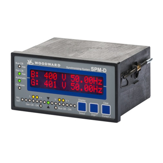
Manual 37259C SPM-D11 - Synchronizing Unit Chapter 5. Display and Operating Elements The foil of the front plate is made of coated plastic. All keys have been designed as touch-sensitive membrane switch elements. The display is a LC-display, consisting of 2 rows each with 16 characters, which are indirectly illuminated red. -
Page 33: Brief Explanation Of The Leds And Push Buttons
Manual 37259C SPM-D11 - Synchronizing Unit Brief Explanation of the LEDs and Push Buttons ≡≡≡≡≡≡≡≡≡≡≡≡≡≡≡≡≡≡≡≡≡≡≡≡≡ LEDs No Description Function Bus CB Free Non-functional Gen CB Free Enable CB Automatic Automatic mode CB close Close command to the CB issued Synchroscope... -
Page 34: Leds
Manual 37259C SPM-D11 - Synchronizing Unit LEDs ≡≡≡≡≡≡≡≡≡≡≡≡≡≡≡≡≡≡≡≡≡≡≡≡≡ Bus CB Free Enable mains circuit breaker here: non-functional Color: green NOTE: This LED is non-functional, as this is a "One-power-circuit-breaker configuration". Gen CB Free Enable generator circuit breaker Color: green The LED "Gen CB Free" indicates that the power circuit breaker has been enabled for operation. - Page 35 Manual 37259C SPM-D11 - Synchronizing Unit Governor output decrease frequency Color: yellow The LED "f-" indicates if the control outputs a pulse to decrease the fre- Three position controller quency. The status of the LED corresponds to the status of the relay "speed lower".
-
Page 36: Push Buttons
Manual 37259C SPM-D11 - Synchronizing Unit Push Buttons ≡≡≡≡≡≡≡≡≡≡≡≡≡≡≡≡≡≡≡≡≡≡≡≡≡ In order to facilitate the setting of the parameters the buttons are equipped with an "AUTOSCROLL" function while the controller is in the configuration mode. It permits the user to rapidly advance to the next setting and configuration screens, the digits, or the cursor position. -
Page 37: Lc Display
Manual 37259C SPM-D11 - Synchronizing Unit LC Display ≡≡≡≡≡≡≡≡≡≡≡≡≡≡≡≡≡≡≡≡≡≡≡≡≡ LC-Display LC-Display Performance values can be monitored from the two-line display, pro- vided that the control is in automatic mode. In configuration mode, the individual parameters are displayed. Display Monitoring in Automatic Mode: Double Voltage / Frequency Display... -
Page 38: Chapter 6. Configuration
Manual 37259C SPM-D11 - Synchronizing Unit Chapter 6. Configuration CAUTION Please note that configuration should not be carried out while the control unit is in operation. NOTE A list of parameters may be found in Appendix B in this manual. -
Page 39: Password Protection
Manual 37259C SPM-D11 - Synchronizing Unit Password Protection The control is equipped with a three-level code and configuration hierarchy, which enables it to project various configuration screens for different categories of users. A distinction is made between: • Code level 0 (CL0) - User: Third party The user assigned this code level may view the monitored values but is prohibited from accessing any pa- rameters. -
Page 40: Direct Configuration
Manual 37259C SPM-D11 - Synchronizing Unit Direct Configuration NOTE To carry out direct configuration, you require a direct configuration cable (Part #5417-557), the LeoPC 1 program (supplied with the cable), and the corresponding configuration files. Please consult the online help installed when the program is installed for a description of the LeoPC 1 PC program and its setup. -
Page 41: Basic Settings
Manual 37259C SPM-D11 - Synchronizing Unit Basic Settings ≡≡≡≡≡≡≡≡≡≡≡≡≡≡≡≡≡≡≡≡≡≡≡≡≡ WARNING Incorrect entries may lead to wrong measuring values and result in damage to the generator! PTs (Voltage Transformers) Rated generator frequency 48.0 to 62.0 Hz Rated Frequency fn = 00.0Hz Enter the rated frequency of the generator (or the utility mains) which in most cases is 50 Hz or 60 Hz. -
Page 42: Cts (Current Transformer)
{X} / 5 A ..Secondary rated current = 5 A at primary rated current = {X} A; NOTE Starting with software version 6.3640 it is possible to perform power measurement for single-phase or three-phase generators with the SPM-D11. The necessary settings have to be made in the following two screens. Connection type generator... -
Page 43: Controller
3 (Enable CB). Frequency Controller The SPM-D11/LSR is equipped with a three-position controller for frequency and does not contain the following screens. Only the screens for setting the three-position controller are available. With the extended version SPM- D 11/LSXR, several controller output signals can be selected via the screens, which are listed by the controller model. - Page 44 Manual 37259C SPM-D11 - Synchronizing Unit Three-Step Controller (SPM-D11/LSR and SPM-D11/LSXR, Setting 'THREE-STEP') Frequency controller ON/OFF Freq. controller ON ....The generator frequency is controlled. The control is executed in for SPM-D11/LSR and various manners depending on the task (no load / isolated operation / SPM-D11/LSXR 'THREE-STEP' synchronization).
- Page 45 Manual 37259C SPM-D11 - Synchronizing Unit Analog Controller Outputs (SPM-D11/LSXR, Settings 'ANALOG' and 'PWM') Controller output signal see table f control output xxxxxxx This configuration screen only appears if the frequency controller is configured as SPM-D11/LSXR 'ANALOG' ANALOG type! The range of the analog output signal is adjusted here. To choose between a current signal in mA or a voltage signal in V, the appropriate jumpers must be connected to the output terminals.
- Page 46 Manual 37259C SPM-D11 - Synchronizing Unit Frequency controller ON/OFF Freq. controller ON ....The generator frequency is controlled. The generator frequency is SPM-D11/LSXR controlled in various manners depending on the task (no load / iso- 'ANALOG'& 'PWM' lated operation / synchronization). The following screens of this function are displayed.
-
Page 47: Voltage Controller
SPM-D11 - Synchronizing Unit Voltage Controller The SPM-D11/LSR is provided with a three-step controller for voltages and does not contain the following screen. Moreover, only the screens for setting the three-step controller exist. Several controller output signals can be selected using the following screen with the SPM-D11/LSRX. Depending on the selected controller type, the following screens belonging to it appear. - Page 48 The optimum setting depends on the behavior of the system. If the gain is too low, the control action becomes slow. If the gain is configured too high, the result is excessive overshoot/undershoot of the desired value. Analog Controller Outputs (SPM-D11/LSXR, Setting 'ANALOG') Controller output signal see table...
- Page 49 Manual 37259C SPM-D11 - Synchronizing Unit Voltage controller - initial state 0 to 100% V control output Init.state 000% This parameter is the start point for the output signal when the frequency controller SPM-D11/LSXR parameter is configured as OFF. The percentage value relates to the range between 'ANALOG' the minimum and maximum values that control unit can output (see below).
-
Page 50: Power Factor Control
Manual 37259C SPM-D11 - Synchronizing Unit Voltage controller - derivative-action time 0.00 to 6.00 s Volt. controller Derivat.Tv=0.00s The derivative-action time TV represents the D-component of the PID controller. SPM-D11/LSXR The D-component of the controller output becomes effective with large variations 'ANALOG' of the offset, e.g. - Page 51 Refer to the parameter settings for the voltage controller starting on page 47. The parameter settings performed for the voltage controller may be applied to the power factor controller as well. Three-Position Controller (SPM-D11/LSR and SPM-D11/LSXR, Setting 'THREE-STEP') Power factor controller insensitivity 0.5 to 25.0 %...
-
Page 52: Real Power Controller
Manual 37259C SPM-D11 - Synchronizing Unit Real Power Controller Real power controller ON/OFF Power controller ON ....During mains/parallel operation the real power is controlled to the pre-selected set point value. The following screens of this option are displayed. OFF ....The power is not controlled, and the following screens of this option not displayed. -
Page 53: Power Set Point Value
Power Set point Value NOTE The SPM-D11 does not take the connection to the utility into consideration. This means that if the plant generates excess power, power will be exported to the utility. If the plant does not generate enough power to meet demand, then power will be imported from the utility. - Page 54 Manual 37259C SPM-D11 - Synchronizing Unit Three-Position Controller (SPM-D11/LSR and SPM-D11/LSXR, Setting 'THREE-STEP') Real power controller insensitivity 0.1 to 25.0 % Power controller Dead band= 00.0% In mains/parallel operation the real power will be controlled so that it does not de-...
- Page 55 Manual 37259C SPM-D11 - Synchronizing Unit Power Limit The generator power is monitored for exceeding the configured threshold value. The excess is signaled with the relay "Power limit". As long as the power is below the threshold value, the relay is energized (the contact is closed).
-
Page 56: Load/Var Sharing
Manual 37259C SPM-D11 - Synchronizing Unit Load/Var Sharing Load sharing ON/OFF Active power Load-share ON ....Real power is distributed among the generators operating in parallel. The generator outputs are distributed depending on the set values. The following screens of this function are displayed OFF ....There is no load sharing control performed, and the following... -
Page 57: Synchronization
Manual 37259C SPM-D11 - Synchronizing Unit Synchronization ≡≡≡≡≡≡≡≡≡≡≡≡≡≡≡≡≡≡≡≡≡≡≡≡≡ Functions of Synchronization Synchronization functions ON/OFF Synchronizing functions ON....Frequency and voltage matching for the generator and busbar is per- formed and a close command is issued. The subsequent screens of this function are displayed. - Page 58 Manual 37259C SPM-D11 - Synchronizing Unit Phase matching control ON/OFF Phase matching ON ....The synchronization is performed with Phase matching control and circuit breaker closure operations are dependent upon the phase an- gle. The relevant phase matching screens are displayed.
-
Page 59: Synchronization Time Monitoring
Manual 37259C SPM-D11 - Synchronizing Unit Phase matching control gain 1 to 36 Phase matching Gain This configuration screen only appears, if the phase matching control is configured Zero phase control = ON When phase matching control is enabled, this gain determines how much the output signal is changed depending on phase difference. -
Page 60: Dead Bus Operation
Manual 37259C SPM-D11 - Synchronizing Unit Dead Bus Operation ≡≡≡≡≡≡≡≡≡≡≡≡≡≡≡≡≡≡≡≡≡≡≡≡≡ If the busbar is in a voltage-free state (dead bus), a direct closing (dead bus start) of the generator circuit breaker (GCB) may be carried out. Dead bus start of power circuit breaker ON/OFF Gen. -
Page 61: Protection
Manual 37259C SPM-D11 - Synchronizing Unit Protection ≡≡≡≡≡≡≡≡≡≡≡≡≡≡≡≡≡≡≡≡≡≡≡≡≡ Generator Reverse/Reduced Power Monitoring Generator real power is monitored to ensure it does not fall below a preset limit. The watchdog assigned to this relay is at terminals 37/38. The relay contact is a N.O. contact. When operating in normal operations the relay is continuously energized. -
Page 62: Generator Overload Monitoring
Manual 37259C SPM-D11 - Synchronizing Unit Generator Overload Monitoring Generator real power is monitored to ensure it does not exceed a preset limit. The watchdog assigned to this relay is at terminals 37/38. The relay contact is a N.O. contact. When operating in normal operations the relay is con- tinuously energized. -
Page 63: Generator Frequency Monitoring
Manual 37259C SPM-D11 - Synchronizing Unit Generator Frequency Monitoring Generator frequency is monitored to ensure it does not exceed or fall below the threshold value. The watchdog assigned to this relay is at terminals 43/44. The relay contact is a N.O. contact. When operating in normal opera- tions the relay is continuously energized. -
Page 64: Generator Voltage Monitoring
Manual 37259C SPM-D11 - Synchronizing Unit Generator Voltage Monitoring The line voltages V of the generator are monitored to ensure they do not exceed or fall below the threshold values. The watchdog assigned to this relay is at terminals 41/42. The relay contact is a N.O. contact. When op- erating in normal operations the relay is continuously energized. -
Page 65: Password
Manual 37259C SPM-D11 - Synchronizing Unit Password ≡≡≡≡≡≡≡≡≡≡≡≡≡≡≡≡≡≡≡≡≡≡≡≡≡ NOTE Once the code level is entered, access to the configuration menus will be allowed for two hours or until another password is entered into the control. If a user needs to exit a code level then code level CS0 should be entered. -
Page 66: Chapter 7. Commissioning
Manual 37259C SPM-D11 - Synchronizing Unit Chapter 7. Commissioning DANGER - HIGH VOLTAGE When commissioning the control, please observe all safety rules that apply to the handling of live equipment. Ensure that you know how to provide first aid in the event of an uncontrolled release of en- ergy and that you know where the first aid kit and the nearest telephone are. - Page 67 Manual 37259C SPM-D11 - Synchronizing Unit Synchronizing the power circuit breaker: a) Disconnect the breaker operation connection to the power circuit breaker; b) The voltage to which the system has to synchronize must be within the permissible range c) The signal "Enable CB" must be enabled.
-
Page 68: Appendix A. Dimensions
Manual 37259C SPM-D11 - Synchronizing Unit Appendix A. Dimensions Configuration plug Configuration plug Front view DIN rail mount option Bottom view 108.8 Back view with connecting terminals SPM-D SPM-D11 2004-08-05 | SPM-D Dimensions spmdww-3204-ab.skf Figure 7-1: Dimensions Page 68/79 © Woodward... -
Page 69: Appendix B. List Of Parameters
Manual 37259C SPM-D11 - Synchronizing Unit Appendix B. List of Parameters Product number P/N _____________________________ Rev _______________________________ Version SPM-D11 _____________________________________________________________ Project _____________________________________________________________________ Serial number S/N _______________ Date ______________________________ Parameter Standard Option Adjustment range Customer settings 100/400V; 1/5 A setting CONFIGURE GENERAL PARAMETERS... - Page 70 Manual 37259C SPM-D11 - Synchronizing Unit Parameter Standard Option Adjustment range Customer settings 100/400V; 1/5 A setting THREE-STEP/ANALOG ANALOG V contr. type ON/OFF Volt. controller ON/OFF Volt. controllerIsol. oper. 1 to 99 V/s 25 V/s Volt. controller Ramp [1] 0.1 to 15.V, [4] 0.5 to 60.0 V 2.0 V...
- Page 71 Manual 37259C SPM-D11 - Synchronizing Unit Parameter Standard Option Adjustment range Customer settings 100/400V; 1/5 A setting CONFIGURE SYNCHRONIZATION ON/OFF Synchronizing functions 0.02 to 0.49 Hz 0.18 Hz Synchronization df max 0.00 to -0.49 Hz -0.10 Hz Synchronization df min...
-
Page 72: Appendix C. Technical Data
Manual 37259C SPM-D11 - Synchronizing Unit Appendix C. Technical Data Measuring values, voltage ----------------------------------------------------------------------------------- Measuring voltage Standard (V )..........[1] 57/100 (120) Vac [4] 230/400 Vac Measuring range ..........[1] 50 to 120 Vac [4] 50 to 400 Vac Measuring frequency ................... 40.0 to 70.0 Hz Accuracy ........................ - Page 73 Manual 37259C SPM-D11 - Synchronizing Unit Analog inputs ----------------------------------------------------------------------------- freely scaleable Resolution........................10 Bit 0/4 to 20 mA input....................load 250 Ω Analog outputs ------------------------------------------------------------------------------ freely scalable Resolution........................12 Bit 0/4 to 20 mA................. external load max. 500 Ω 0 to 10 Vdc ................ internal source resistance 500 Ω...
-
Page 74: Appendix D. Service Options
≡≡≡≡≡≡≡≡≡≡≡≡≡≡≡≡≡≡≡≡≡≡≡≡≡ If a control (or any part of an electronic control) is to be returned to Woodward for repair, please contact Wood- ward in advance to obtain a Return Authorization Number. When shipping the control(s), attach a tag with the following information: •... -
Page 75: Packing A Control
Stuttgart [+49 (0) 711-789 54-0]. They will help expedite the processing of your order through our distributors or local service facility. To expedite the repair process, contact Woodward in advance to obtain a Return Authoriza- tion Number, and arrange for issue of a purchase order for the control(s) to be repaired. No work can be started until a purchase order is received. -
Page 76: How To Contact Woodward
+49 (0) 711-789 54-100 e-mail: sales-stuttgart@woodward.com For assistance outside Germany, call one of the following international Woodward facilities to obtain the address and phone number of the facility nearest your location where you will be able to get information and service. Facility... -
Page 77: Engineering Services
SPM-D11 - Synchronizing Unit Engineering Services ≡≡≡≡≡≡≡≡≡≡≡≡≡≡≡≡≡≡≡≡≡≡≡≡≡ Woodward Industrial Controls Engineering Services offers the following after-sales support for Woodward prod- ucts. For these services, you can contact us by telephone, by e-mail, or through the Woodward website. • Technical support •... -
Page 78: Technical Assistance
Manual 37259C SPM-D11 - Synchronizing Unit Technical Assistance ≡≡≡≡≡≡≡≡≡≡≡≡≡≡≡≡≡≡≡≡≡≡≡≡≡ If you need to telephone for technical assistance, you will need to provide the following information. Please write it down here before phoning: Contact Your company______________________________________________ Your name_________________________________________________ Phone number ______________________________________________... - Page 79 Telefon +49 (0) 711-789 54-0 • Fax +49 (0) 711-789 54-100 sales-stuttgart@woodward.com Homepage http://www.woodward.com/smart-power Woodward has company-owned plants, subsidiaries, and branches, as well as authorized distributors and other authorized service and sales facilities throughout the world. Complete address/phone/fax/e-mail information for all locations is available on our website (www.woodward.com).
Need help?
Do you have a question about the SPM-D11 and is the answer not in the manual?
Questions and answers