
Related Manuals for Woodward 9907-026


Summary of Contents for Woodward 9907-026
- Page 1 Product Manual 02029 (Revision B) Original Instructions Load Sharing Module Analog Output CE Compliant Installation and Operation Manual...
- Page 2 Woodward reserves the right to update any portion of this publication at any time. Information provided by Woodward is believed to be correct and reliable. However, no responsibility is assumed by Woodward unless otherwise expressly undertaken.
-
Page 3: Table Of Contents
6. S ..............21 HAPTER ERVICE PTIONS Product Service Options ..................21 Woodward Factory Servicing Options ..............22 Returning Equipment for Repair ................22 Replacement Parts ....................23 Engineering Services .................... 23 How to Contact Woodward ................... 24 ... -
Page 4: Warnings And Notices
Start-up On- and off-highway Mobile Applications: Unless Woodward's control functions as the supervisory control, customer should install a system totally independent of the prime mover control system that... -
Page 5: Electrostatic Discharge Awareness
Do not touch the components or conductors on a printed circuit board with your hands or with conductive devices. To prevent damage to electronic components caused by improper handling, read and observe the precautions in Woodward manual 82715 , Guide for Handling and Protection of Electronic Controls, Printed Circuit Boards, and Modules. - Page 6 Load Sharing Module (Analog Output) Manual 02029 Woodward...
-
Page 7: Chapter 1. General Information
Import/Export Control, and Precise Frequency Control. Figure 1-1 shows a typical system using a Load Sharing Module. Additional Information The literature listed here contains information on the 9907-026 Load Sharing Module and associated equipment and can be ordered from any Woodward location listed on the back page. -
Page 8: Figure 1-1. Typical System Using Load Sharing Module
Load Sharing Module (Analog Output) Manual 02029 Figure 1-1. Typical System Using Load Sharing Module Woodward... -
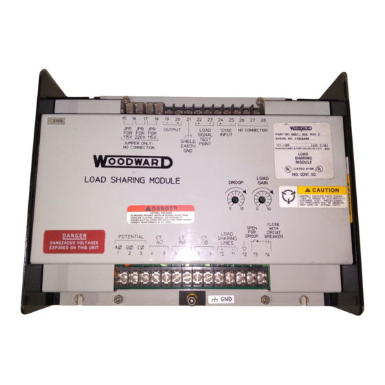
Page 9: Figure 1-2. Outline Drawing Of Load Sharing Module
Manual 02029 Load Sharing Module (Analog Output) Figure 1-2. Outline Drawing of Load Sharing Module Woodward... -
Page 10: Figure 1-3. Plant Wiring Diagram
Load Sharing Module (Analog Output) Manual 02029 Figure 1-3. Plant Wiring Diagram Woodward... -
Page 11: Chapter 2. Installation
For this information, see the plant wiring diagram for your specific system. Woodward manual 25070, Electronic Control Installation Guide, also contains general information on wiring for electronic controls. -
Page 12: Figure 2-1. Open Delta Connection
Connect the wiring to the SPM Synchronizer (if used). Use shielded, twisted-pair wire. Load Sharing Lines Connect the wiring for the load sharing lines. Use shielded, twisted-pair wire. Load Sharing lines are not required if the Load Sharing Module is to be used in the droop mode only. Woodward... -
Page 13: Installation Check
Check that all electrical connections are correctly made and that all terminal screws are tight. Check that shielded wire is installed on the wires indicated in the plant wiring diagram, and that all shields are grounded on one end only. Woodward... -
Page 14: Chapter 3. Calibration
Remove the load from the generator set. 10. Check the voltage between terminals 22 and 23. This voltage should be 0.0 ±0.25 Vdc. If this voltage is not correct, the Load Sharing Module unit is faulty; return it to Woodward for repair. Woodward... -
Page 15: Phasing Check
25. Reconnect the Phase B CT wire to terminal 7. 26. If the reading in step 23 was correct, proceed to step 27. If the reading in step 23 was not correct, proceed to the Phase Correction Procedure below. Woodward... -
Page 16: Phase Correction Procedure
Module can be changed with the generator set running; however, remove all load before any changes in connections are made. Do not disconnect a wire from a current transformer with load on the system. After the phase correction procedure has been completed, remove the terminal strip and the resistors. Woodward... -
Page 17: Figure 3-1. Temporary Ct Connection
Shut the generator set down and reverse the Phase A wires on terminals 4 and 5. Start the engine and apply full load. 10. Measure the load signal voltage between terminals 22 and 23 and record this voltage. 11. Shut down the generator set. Woodward... - Page 18 30. Shut the generator set down and reverse the phase B wires on the CT input terminals 31. Start the engine and apply full load. 32. Measure the load signal voltage between terminals 22 and 23 and record this voltage. 33. Shut down the generator set. Woodward...
-
Page 19: Load Gain Adjustment
For this procedure, the generator set must be running isochronously, not paralleled, and with a power factor of unity (1.0 ±0.1). Start the generator set and run at full load. Measure the load signal voltage and adjust the LOAD GAIN potentiometer for 6.0 ±0.1 Vdc. Woodward... -
Page 20: Droop Adjustment
If your system requires a load signal voltage as low as three volts, consult the Woodward Governor Company for suggestions for possible remedies. The most accurate calibration is made at full load. However, if it is... - Page 21 If it is necessary to set the droop without pulling 100% load, set the RATED SPEED potentiometer (in step 1) accordingly for desired percent droop. For example: at 5% droop, running at only 50% load, the RATED SPEED potentiometer would be set at 61.5 Hz. in step 1. Figure 3-2. Droop Adjustment Woodward...
-
Page 22: Chapter 4. Theory Of Operation
The controller circuit of each Load Sharing Module includes a potentiometer to adjust each generator set's load signal so that the load signal voltage of each is the same at full load. Woodward... -
Page 23: Figure 4-1. Block Diagram
Manual 02029 Load Sharing Module (Analog Output) Figure 4-1. Block Diagram Woodward... -
Page 24: Isochronous Load Sharing
(when running in droop). If an SPM-A Synchronizer is used with the system, it biases the output of the Load Sharing Module at the summing point, in order to synchronize the generator set with the bus. Woodward... -
Page 25: Chapter 5. Troubleshooting
SCRs is especially noisy.) Keep wire lengths to a minimum. Route wiring through conduit when possible. Use single point grounds. Take control power right off battery. (Do not use distribution points or take off starter.) Run additional equipment off separate battery wires. Woodward... - Page 26 Engine does not Terminals 13 and 14 not Jumper Load Sensor terminals 13 properly share shorted. Load Sensor in and 14. Observe engine operation. load with other droop. Replace wiring or switch as required. units. Woodward...
-
Page 27: Chapter 6. Service Options
Woodward systems and components for the retrofits and overhauls, long term service contracts, emergency repairs, etc. You can locate your nearest Woodward distributor, AISF, RER, or RTR on our website at: www.woodward.com/directory... -
Page 28: Woodward Factory Servicing Options
Flat Rate Remanufacture: Flat Rate Remanufacture is very similar to the Flat Rate Repair option with the exception that the unit will be returned to you in “like- new” condition and carry with it the full standard Woodward product warranty (Woodward Product and Service Warranty 5-01-1205). This option is applicable to mechanical products only. -
Page 29: Replacement Parts
Engineering Services Woodward offers various Engineering Services for our products. For these services, you can contact us by telephone, by email, or through the Woodward website. Technical Support ... -
Page 30: How To Contact Woodward
Load Sharing Module (Analog Output) Manual 02029 How to Contact Woodward For assistance, call one of the following Woodward facilities to obtain the address and phone number of the facility nearest your location where you will be able to get information and service. - Page 31 Manual 02029 Load Sharing Module (Analog Output) Woodward...
- Page 32 Email and Website—www.woodward.com Woodward has company-owned plants, subsidiaries, and branches, as well as authorized distributors and other authorized service and sales facilities throughout the world. Complete address / phone / fax / email information for all locations is available on our website.
Need help?
Do you have a question about the 9907-026 and is the answer not in the manual?
Questions and answers