
Related Manuals for Woodward SECM112


Summary of Contents for Woodward SECM112
- Page 1 Product Manual 26634 (Revision C, 03/2022) Original Instructions SECM112 Digital Control Vehicular Applications Hardware Only Installation Manual EC-US-L1...
- Page 2 Revisions— A bold, black line alongside the text identifies changes in this publication since the last revision. Woodward reserves the right to update any portion of this publication at any time. Information provided by Woodward is believed to be correct and reliable. However, no responsibility is assumed by Woodward unless otherwise expressly undertaken.
-
Page 3: Table Of Contents
PTIONS Product Support Options ..........................15 Product Service Options ..........................15 Returning Equipment for Repair ......................... 16 Replacement Parts ............................16 Engineering Services ..........................17 Contacting Woodward’s Support Organization ................... 17 Technical Assistance ..........................18 ........................19 EVISION ISTORY Woodward... - Page 4 Figure 2-2. SECM112 Outline ........................10 Figure 2-3. Preferred SECM112 Mounting Orientations ................11 Figure 2-4. Acceptable SECM112 Mounting Orientations ................11 Figure 2-5. Not Recommended SECM112 Mounting Orientations ............. 11 Figure 2-6. Harness Clearance ........................12 Figure 2-7. SECM Connector Orientations ....................12 Figure 2-8.
-
Page 5: Warnings And Notices
Manual 26634 SECM112 Digital Control Warnings and Notices Important Definitions This is the safety alert symbol used to alert you to potential personal injury hazards. Obey all safety messages that follow this symbol to avoid possible injury or death. •... - Page 6 Manual 26634 SECM112 Digital Control On- and Off-Highway Mobile Applications: Unless Woodward's control functions as the supervisory control, customer should install a system totally independent of the prime mover control system that monitors for supervisory control of engine (and takes appropriate...
-
Page 7: Regulatory Compliance
Manual 26634 SECM112 Digital Control Regulatory Compliance International Compliance UNECE Type approved to UNECE Regulations 10, 67, and 110. Woodward EC-US-L1... -
Page 8: Electrostatic Discharge Awareness
Do not touch the components or conductors on a printed circuit board with your hands or with conductive devices. To prevent damage to electronic components caused by improper handling, read and observe the precautions in Woodward manual 82715 , Guide for Handling and Protection of Electronic Controls, Printed Circuit Boards, and Modules. -
Page 9: Chapter 1. General Information
The SECM112 is designed for engine mount operation with the vibration isolators. If the SECM112 is mounted on a bracket not provided by Woodward, the bracket needs to be evaluated in the application. It is possible for a bracket resonance to be incompatible with the SECM112 product, causing premature failure of the module. -
Page 10: Figure 1-1. Location Of Accelerometer To Measure Mounting Vibration
Customers can verify the temperature in the desired mounting location by placing a thermocouple in the air near the operating SECM112. If the external ambient conditions are not worst-case, this needs to be taken into consideration when measuring the SECM112 package temperature. If the measured air temperature when operating at worst-case (fastest) engine speed and worst-case (hottest) ambient conditions is less than 105 °C, the mounting location thermal stress is acceptable for the SECM112. -
Page 11: Secm112 Installation
SECM112 Installation Isolators The SECM112 has 4 mounting feet and Figure 2-1 illustrates the isolator assembly pre-assembled on the module. All variants of the module come from the factory with the grommet and bushing pre-installed. Washers must be used and are provided by Woodward (default) or the user (upon request). -
Page 12: Figure 2-2. Secm112 Outline
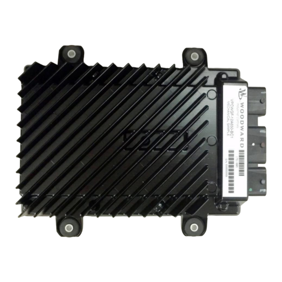
Manual 26634 SECM112 Digital Control Figure 2-2. SECM112 Outline Woodward EC-US-L1... -
Page 13: Figure 2-3. Preferred Secm112 Mounting Orientations
SECM112 Digital Control Orientation The SECM112 connector is rated for high pressure spray to IP6K9K; however, it is not recommended to mount with the connector facing up or with the harness routed upward directly from the module. This orientation can allow moisture to run down the harness to the wire seals in the connectors. The module must be mounted with the heat fins facing outwards to maximize airflow over the fins. -
Page 14: Figure 2-6. Harness Clearance
Figure 2-6. Harness Clearance Connector Information The SECM112 mating connectors, terminals, wire cap (backshells), and wire plug part numbers are listed in Table 2-1 below. Note that the center grey connector has the opposite orientation to the others. All unused pins must be plugged with the proper wire plugs to maintain environmental integrity. Reference Molex CMC connector application specification # AS-64319-002 rev. -
Page 15: Figure 2-8. Connector Physical Pinout
Manual 26634 SECM112 Digital Control Figure 2-8. Connector Physical Pinout Table 2-1. Connector System Part Numbers Item Molex PN Woodward PN Connectors (for Left Exit) 32-pin, black (A), left wire output 643191211 32-pin, grey (C), right wire output 643193218 48-pin, brown (B), left wire output... - Page 16 Manual 26634 SECM112 Digital Control Table 2-1. Connector System Part Numbers (cont’d.) Item Molex PN Woodward PN Hand Crimper Tools 0.6 mm (0.35 to 0.5 mm²) 638119100 8996-2227 0.6 mm (0.5 to 0.75 mm²) 638119200 8996-2228 1.5 mm (0.5 to 1 mm²)
-
Page 17: Chapter 3 Product Support And Service Options
• An Authorized Independent Service Facility (AISF) provides authorized service that includes repairs, repair parts, and warranty service on Woodward's behalf. Service (not new unit sales) is an AISF's primary mission. • A Recognized Engine Retrofitter (RER) is an independent company that does retrofits and... -
Page 18: Returning Equipment For Repair
To prevent damage to electronic components caused by improper handling, read and observe the precautions in Woodward manual 82715, Guide for Handling and Protection of Electronic Controls, Printed Circuit Boards, and Modules. -
Page 19: Engineering Services
Field Service engineering on-site support is available, depending on the product and location, from one of our Full-Service Distributors. The field engineers are experienced both on Woodward products as well as on much of the non-Woodward equipment with which our products interface. -
Page 20: Technical Assistance
SECM112 Digital Control Technical Assistance If you need to contact technical assistance, you will need to provide the following information. Please write it down here before contacting the Engine OEM, the Packager, a Woodward Business Partner, or the Woodward factory: General... -
Page 21: Revision History
Revised graphic accompanying Table 2-1 (Chapter 2) • Corrected mounting bolt size and added torque (Chapter 2) • Eliminated Woodward part number of connector pin removal tools in Table 2-1 (Chapter 2) • Added Table 2-2 Connector Kit description (Chapter 2) Changes in Revision B—... - Page 22 Email and Website—www.woodward.com Woodward has company-owned plants, subsidiaries, and branches, as well as authorized distributors and other authorized service and sales facilities throughout the world. Complete address / phone / fax / email information for all locations is available on our website.
Need help?
Do you have a question about the SECM112 and is the answer not in the manual?
Questions and answers