
Subscribe to Our Youtube Channel
Related Manuals for Woodward MicroNet TMR 5009


Summary of Contents for Woodward MicroNet TMR 5009
- Page 1 ® MicroNet TMR 5009 Digital Control System Volume 2 Installation/Hardware Manual Manual 85580V2 (Revision E)
- Page 2 Revisions—Text changes are indicated by a black line alongside the text. Woodward Governor Company reserves the right to update any portion of this publication at any time. Information provided by Woodward Governor Company is believed to be correct and reliable. However, no responsibility is assumed by Woodward Governor Company unless otherwise expressly undertaken.
-
Page 3: Table Of Contents
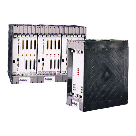
EPLACEMENT Introduction......................70 Main Power Supply....................70 Kernel Power Supply (A1) ..................72 CPU Module ......................73 Analog and Discrete I/O Modules.................74 Serial Input/Output (SIO) Module .................75 Termination Modules ....................76 Diagnostics ......................78 System Troubleshooting Guide ................79 6. H ..........86 HAPTER ARDWARE PECIFICATIONS Woodward... - Page 4 ..............102 HAPTER ERVICE PTIONS Product Service Options..................102 Returning Equipment for Repair................ 103 Replacement Parts .................... 104 How to Contact Woodward................104 Engineering Services..................105 Technical Assistance..................106 ..................108 ECLARATIONS Illustrations and Tables Figure 2-1. Control and Power Chassis ..............3 Figure 2-2.
- Page 5 Table 5-2. On-Line Test Failure Messages............78 Table 5-3. Discrete In Cable Connections ............81 Table 5-4. Relay Cable Connections ..............82 Table 5-4. Relay Cable Connections (cont.) ............83 Table 5-5. Analog Combo Module................84 Table 5-6. DTM Interconnect Cables W14, W15, W16........85 Woodward...
-
Page 6: Regulatory Compliance
CAUTION—MAXIMUM VOLTAGE To comply with CE Marking under the European Low Voltage Directive (LVD), the maximum external circuit voltage for both the Discrete Inputs and Relay Output circuit are limited to 18–32 Vdc maximum. Woodward... -
Page 7: Electrostatic Discharge Awareness
PCB from the control cabinet, place it in the antistatic protective bag. CAUTION—ELECTROSTATIC DISCHARGE To prevent damage to electronic components caused by improper handling, read and observe the precautions in Woodward manual 82715, Guide for Handling and Protection of Electronic Controls, Printed Circuit Boards, and Modules. Woodward... - Page 8 5009 Installation/Hardware Manual 85580V2 Woodward...
-
Page 9: Chapter 1. General Information
9907-886, 9907-887, 9907-889, 9907-890, 9907-991, 9907-1000, 9907-1001, 9907-1002, 9907-1003, 9907-1004, 9907-1005, 9907-1006, 9907-1007, 9907-1011, 9907-1012. This volume provides hardware description, installation, and troubleshooting information for the Woodward 5009 Control System. It includes: • A list of all system hardware •... -
Page 10: Chapter 2. Hardware Description
Cooling fans are located on the top of the main chassis; with one fan per 6-slot card rack. The power supply chassis contains two cooling fans: one on top and one on the bottom of the chassis. See Figure 2-1. These fans run any time the 5009 chassis is powered up. Woodward... -
Page 11: System Power Supplies
24 V to each kernel section (A, B, C) of the 5009 control. Mounted in the main control chassis are three Kernel Power Supplies, which convert 24 V to 5 V at 10 A for their kernel’s CPU and I/O modules. Woodward... -
Page 12: Module Descriptions
Also at the top and bottom are two handles which, when toggled, move the modules out just far enough for the boards to disengage the motherboard connectors. Each module is protected with a molded plastic cover to prevent accidental component damage. Woodward... -
Page 13: Figure 2-2. Kernel Power Supply Block Diagram
PCI engineering workstation, OpView or other RS-232 compatible devices. The CPU has a PCMCIA (Personal Computer Memory Card International Association) slot on its front panel. The PCMCIA slot is used to down load application files to the CPU module. Woodward... -
Page 14: Figure 2-3. Cpu Module
Three filter assemblies (one per CPU) are provided with each system to protect the CPU from external system noise. These filter assemblies are shipped separately from the control and can be easily installed if use of the CPU port is required. Woodward... -
Page 15: Figure 2-4. Cpu Communications Port Filter Kit Installation Instructions
Manual 85580V2 5009 Installation/Hardware Figure 2-4. CPU Communications Port Filter Kit Installation Instructions Woodward... -
Page 16: Figure 2-5. Mpu And Analog I/O Module
5009 control. An ATM houses circuitry to: • route each input signal to the system’s three independent (rack mounted) analog modules • produce each output signal by summing the three independent analog modules’ respective outputs Woodward... -
Page 17: Figure 2-6. Analog Termination Module Diagram
For dual coil actuators, kernels A and B drive one coil and kernel C drives the second coil. Current readback circuitry identifies failed modules and allows the remaining outputs to be adjusted accordingly. Figure 2-6. Analog Termination Module Diagram Woodward... -
Page 18: Figure 2-7. Discrete Input/Output Module
Each DTM connects to the control’s three independent Discrete I/O modules through individual cables, and provides a common cage-clamp terminal connection for customer field wiring. A DTM contains circuitry for six contact inputs, three relay outputs and houses circuitry to: Woodward... - Page 19 When they are open, they are periodically closed individually, to ensure that they close. Any failures are annunciated, and further testing is disabled. Woodward...
-
Page 20: Figure 2-8. Dtm Block Diagram
A and B kernels. Each SIO module includes four serial ports. Ports 1 and 2 are RS-232 communications based ports only. Ports 3 and 4 can be configured for RS-232, RS-422, or RS-485 communications. Refer to Chapter 4 of this volume for port related communication capabilities. Woodward... -
Page 21: Cabinet (Optional)
The OpView™ Operator Interface is a computer-based work-station that functions as a touch screen annunciator and operator control panel for Woodward digital control systems. This work-station allows an operator to remotely view operating inputs, vary control setpoints, and issue Run mode commands. -
Page 22: Chapter 3. Mechanical Installation
Discrete I/O Cable (10 ft/ 3 m) Standard W14 - W19 DTM to DTM Cable (6”/15 cm) Standard Control to PCI Cable (10 ft/3 m) Standard MISC. - A ATM Ground Terminals (used on DIN rail) Standard MISC. - B CPU Comm. Port Filters Standard Woodward... -
Page 23: Figure 3-1. Hardware Identification
Manual 85580V2 5009 Installation/Hardware Figure 3-1. Hardware Identification Woodward... -
Page 24: Unit Location
5. Connect Cabinet to earth ground using a 10 mm² (8 AWG) or larger wire or braid. WARNING—EARTHING CONDUCTOR Leakage current exceeds 3.5 mA. The earthing conductor is required for safety. Woodward... -
Page 25: Figure 3-2. Cabinet Dimensions
Manual 85580V2 5009 Installation/Hardware Figure 3-2. Cabinet Dimensions Before beginning installation successfully identify all components and read this entire chapter. Woodward... -
Page 26: Install 5009 Control And Power Chassis
5. Verify that both the control and power chassis are at earth ground potential, and if they are not, connect them to earth ground via a 3 mm² (12 AWG) or larger yellow/green wire or braid. Figure 3-3. Chassis-to-Chassis Power Cable W1-B Woodward... -
Page 27: Install Modules
CAUTION—INSTALLING MODULES If resistance is encountered when installing a module, do not force the module. Remove the module and check the connectors for bent contacts or foreign objects. Forcing a module into place may break the connector. Woodward... -
Page 28: Figure 3-4A. Outline Drawing Of 5009 Main Chassis
5009 Installation/Hardware Manual 85580V2 Figure 3-4a. Outline Drawing of 5009 Main Chassis Woodward... -
Page 29: Figure 3-4B. Outline Drawing Of 5009 Main Chassis
Manual 85580V2 5009 Installation/Hardware Figure 3-4b. Outline Drawing of 5009 Main Chassis Woodward... -
Page 30: Figure 3-4C. Outline Drawing Of 5009 Power Chassis
5009 Installation/Hardware Manual 85580V2 Figure 3-4c. Outline Drawing of 5009 Power Chassis Woodward... -
Page 31: Figure 3-5. Outline Diagram Of Module With Label
Manual 85580V2 5009 Installation/Hardware Figure 3-5. Outline Diagram of Module with Label Figure 3-6. Module Location Diagram Woodward... -
Page 32: Install Analog Termination Modules
ATMs. See Figure 3-8. 7. Connect a 12 AWG (4.0 mm²) green/yellow wire between each ground terminal and ATM terminal “Chassis Ground”. This wire should be kept as short as possible and be no longer than six inches (15 cm) in length. Woodward... -
Page 33: Figure 3-7. Din Rail & Atm Outline Drawing
Manual 85580V2 5009 Installation/Hardware Figure 3-7. DIN Rail & ATM Outline Drawing Woodward... -
Page 34: Install Discrete Field Termination Modules
4. If the panel the DTMs are mounted on is not at earth ground potential connect it to earth ground via a 12 AWG (4.0 mm²) or larger green/yellow wire or braid; keeping the wire/braid as short as possible. Woodward... -
Page 35: Figure 3-9. Dtm Outline Drawing
Manual 85580V2 5009 Installation/Hardware Figure 3-9. DTM Outline Drawing Woodward... -
Page 36: Figure 3-10. Dtm Mounting Configuration
5009 Installation/Hardware Manual 85580V2 Figure 3-10. DTM Mounting Configuration Woodward... -
Page 37: Install Opview™ Interface (If Included)
See Figure 3-11. Reference PowerStation manual included for further installation instructions. 2. Drill mounting holes per Figure 3-11. 3. Place the OpView in position, install 8-32 mounting nuts onto the studs, and tighten them securely. Figure 3-11. OpView Outline Drawing Woodward... -
Page 38: Figure 3-12. Mounting Template
5009 Installation/Hardware Manual 85580V2 Option 2— Place the OpView in position, install the six mounting clamps to secure the unit into place, and tighten securely. Figure 3-12. Mounting Template Woodward... -
Page 39: Chapter 4. Electrical Installation
2. Connect a grounding cable, 10 mm² (8 AWG) or larger, from an acceptable earth ground to the cabinet frame. System Cables (if cabinet is not included) If the system was provided with a cabinet, no cable installation is required, and you can go directly to the Input Power installation instructions. Woodward... -
Page 40: Shields And Grounding
Relay outputs, contact inputs, and power supply wiring do not normally require shielding, but can be shielded if desired. For compliance with EMC standards, it is required that all analog and discrete input/output wiring be separated from all power wiring. Woodward... -
Page 41: Input Power
Use only time-delay fuses or circuit breakers to avoid nuisance trips. A fixed wiring installation is required. Power supply leakage current exceeds 3.5 mA so a protective earth ground connection is required. Woodward... - Page 42 Significant inrush currents are possible when current is applied to the main power supply. The magnitude of the inrush current depends on the power source impedance, so Woodward cannot specify the maximum inrush current. Time- delay fuses or circuit breakers must be used to avoid nuisance trips.
-
Page 43: Speed Sensor Inputs
MPU clearance is recommended to be 0.25 to 1.02 mm (0.010 to 0.040 inch) from tooth face to pole piece. For information on selecting the correct MPU or gear size, please refer to Woodward manual 82510. See Figure 4-2 for wiring schematic. -
Page 44: Figure 4-2. Example Mpu Interface Wiring Diagram
Each channel’s prox return input accepts 5–28 Vdc. Alternatively with either 12 Vdc or 24 Vdc open collector probes. When interfacing to open collector type probes a pullup resistor between the four voltage terminal and the proximity return terminal is required. Figure 4-2. Example MPU Interface Wiring Diagram Woodward... -
Page 45: Figure 4-3A. Example 24 V Proximity Probe Wiring Diagram
Manual 85580V2 5009 Installation/Hardware Figure 4-3a. Example 24 V Proximity Probe Wiring Diagram Figure 4-3b. Example 12 V Proximity Wiring Diagram Woodward... - Page 46 If the MPU device is not providing a voltage greater than 1.5 Vrms, the MPU device should be moved closer to the gear where speed is being monitored. The following graph shows the minimum voltage necessary to detect speed at the various frequencies. Woodward...
-
Page 47: Analog Inputs
Isolation is provided through diodes on the power and common lines. This 24 Vdc output is capable of providing 24 Vdc with +10% regulation. Power connections are be made through terminals located on system ATMs. Woodward... -
Page 48: Figure 4-4. Example Analog Input Wiring Diagrams
Cable shields must be electrically continuous from the signal source to the point the signal wire enters the 5009 Analog Termination Module. • ATM terminals accept wires from 0.08–2.5 mm² (27–12 AWG). Figure 4-4. Example Analog Input Wiring Diagrams Woodward... -
Page 49: Analog Outputs
The actuator output drive currents can be programmed to interface with Woodward Governor Company actuators (typically 20–160 mA drive currents) or non-Woodward actuators (4–20 mA drive currents). Each actuator output can be individually configured to interface with Woodward or non-Woodward type actuators. -
Page 50: Figure 4-6. Example Single Coil Actuator Wiring Diagram
Dither is a low frequency (25 Hz) signal consisting of a 5 millisecond pulse modulated onto the control’s DC actuator-drive current to reduce stiction in linear type actuators. Woodward TM-type actuators typically require dither. See Volume #3 of this manual for details on adjusting dither. -
Page 51: Dtm Contact Inputs (F/T Relay-Discrete In)
Contacts must change state for a maximum of 40 milliseconds and a minimum of 20 milliseconds for the control to sense and register a change in state. Woodward... -
Page 52: Figure 4-8. Optional Internal 24Vdc Contact Wetting Configuration
DTM terminals 33 & 34, and terminals 33 & 35. If an external power source is used for contact wetting, the external source’s common must be connected to the DTM’s discrete input commons (terminals 34 & 35). Figure 4-8. Optional Internal 24Vdc Contact Wetting Configuration Woodward... -
Page 53: Figure 4-9. Optional External Contact Wetting Configurations
4 mA @ 14 Vdc (4 mA @ 70 Vdc) to recognize a closure command. • Verify that the correct input terminals are wired to with respect to the level of contact wetting voltage used. Woodward... -
Page 54: Dtm Relay Outputs (F/T Relay Outputs)
The relay output would continue to be closed. Once a relay output is closed, the output’s individual relays are periodically opened and re-closed, to ensure that they were in the correct state, and that they change state. Woodward... - Page 55 (on the left of the graph) is the level of voltage that will be developed across the load due to leakage current. 3. If the developed load voltage (from the graph) is less than the load’s drop-out voltage, latent fault detection can be used with the circuit. Woodward...
-
Page 56: Figure 4-10. Latent Fault Detection Verification Graph-18-32 Vdc Circuitry
Vac line to the 110 V line, a total load resistance of 900 Ω is needed. By placing a properly rated 3600 Ω resistor in shunt with the load, (1200//3600 900) LFD can be used. Figure 4-10. Latent Fault Detection Verification Graph—18–32 Vdc Circuitry Woodward... -
Page 57: Figure 4-11. Latent Fault Detection Verification Graph-88-132 Vac Circuitry
Manual 85580V2 5009 Installation/Hardware Figure 4-11. Latent Fault Detection Verification Graph—88–132 Vac Circuitry Figure 4-12. Latent Fault Detection Verification Graph—100–150 Vdc Circuitry Woodward... - Page 58 Refer to Figure 4-13. LFD can be jumper configured to be compatible with the following circuit voltages: • 18–32 Vdc circuit power (meets CE & UL ratings) • 88–132 Vac circuit power (meets UL ratings only) • 100–150 Vdc circuit power (meets UL ratings only) Woodward...
-
Page 59: Figure 4-13. Jumper And Relay Location Diagram
Manual 85580V2 5009 Installation/Hardware Figure 4-13. Jumper and Relay Location Diagram Woodward... -
Page 60: Figure 4-14. Dtm Labels
When using high voltage relay circuit power, it is recommended that care be taken not to touch exposed connectors when replacing relays or cables. If possible remove relay circuit power from all DTM relays before replacing any DTM relay or cable. Woodward... -
Page 61: Serial Communications
(unless SIO-B is installed), Alarm/Trip printer driver port. It can also be configured to automatically become the PCI interface port if CPU-C fails. • CPU-C port (RS-232) functions as a DDE communication port for PCI. • SIO-A Port 1 (RS-232) functions as an Alarm/Trip Printer driver port. Woodward... - Page 62 5009 Installation/Hardware Manual 85580V2 • SIO-A port 2 (RS-232) functions as an interface port to Woodward’s servPanel program. • SIO-A port 3 (RS-232/422/485) functions as Modbus #1 port 1. • SIO-A port 4 (RS-232/422/485) functions as Modbus #2 port 1 or DDE communication for PCI.
-
Page 63: Figure 4-16. Cpu Communications Port
Manual 85580V2 5009 Installation/Hardware Figure 4-16. CPU Communications Port Figure 4-17. Typical Communications Cable Connections Woodward... -
Page 64: Printer
RS-232 communications is limited to 15 m (50 ft) or less. However with the use of an RS-232 to RS-422 converter or Woodward’s SIO module, the OpView can be installed up to 1220 m (4000 ft) from the control (see Volume 4 of this manual). -
Page 65: Control Wiring Diagrams
6 Confirm each connection before operating unit. 7 All analog inputs must be isolated from earth ground. 8 Follow authorized standards for conduit loading and sealing. 9 All wires to terminal blocks shall have wire markers, marked with associated terminal number. Woodward... -
Page 66: Figure 4-18A. Cabinet-Device Location Diagram
5009 Installation/Hardware Manual 85580V2 Figure 4-18a. Cabinet—Device Location Diagram Woodward... -
Page 67: Figure 4-18B. Cabinet-Device Location Diagram
Manual 85580V2 5009 Installation/Hardware Figure 4-18b. Cabinet—Device Location Diagram Woodward... -
Page 68: Figure 4-19. System Cable Layout Diagram
5009 Installation/Hardware Manual 85580V2 Figure 4-19. System Cable Layout Diagram Woodward... -
Page 69: Figure 4-20. Power Supply Wiring Diagram
Manual 85580V2 5009 Installation/Hardware Figure 4-20. Power Supply Wiring Diagram Woodward... -
Page 70: Figure 4-21. Atm-1 Wiring Diagram
5009 Installation/Hardware Manual 85580V2 Figure 4-21. ATM–1 Wiring Diagram Woodward... -
Page 71: Figure 4-22. Atm-2 Wiring Diagram
Manual 85580V2 5009 Installation/Hardware Figure 4-22. ATM–2 Wiring Diagram Woodward... -
Page 72: Figure 4-23. Dtm-1 Wiring Diagram
5009 Installation/Hardware Manual 85580V2 Figure 4-23. DTM–1 Wiring Diagram Woodward... -
Page 73: Figure 4-24. Dtm-2 Wiring Diagram
Manual 85580V2 5009 Installation/Hardware Figure 4-24. DTM–2 Wiring Diagram Woodward... -
Page 74: Figure 4-25. Dtm-3 Wiring Diagram
5009 Installation/Hardware Manual 85580V2 Figure 4-25. DTM–3 Wiring Diagram Woodward... -
Page 75: Figure 4-26. Dtm-4 Wiring Diagram
Manual 85580V2 5009 Installation/Hardware Figure 4-26. DTM–4 Wiring Diagram Woodward... -
Page 76: Figure 4-27. Opview Wiring Diagram
5009 Installation/Hardware Manual 85580V2 Figure 4-27. OpView Wiring Diagram Figure 4-28. OpView Cable Diagram Figure 4-29. Optional Alarm Printer Diagram Woodward... -
Page 77: System Power-Up
CPU to boot-up before both CPUs will go to a running state. WARNING—VERIFY CALIBRATION Improperly calibrated devices can cause turbine damage and possible personnel injury or death. Before starting the turbine for the first time, and periodically thereafter, verify the calibration of all external input and output devices. Woodward... -
Page 78: Chapter 5. Troubleshooting And Module Replacement
If after following this chapter’s guidance the cause of a problem cannot be found, contact the Woodward technical assistance group. CAUTION—QUALIFIED PERSONNEL Only qualified service personnel should perform the following module replacement procedures. - Page 79 6. With even pressure exerted at the top and bottom of the supply’s front panel, firmly push the unit into place. 7. Tighten the screws that secure the module in place (two at the top and two at the bottom). 8. Re-apply power to the input of the power supply. Woodward...
-
Page 80: Kernel Power Supply (A1)
Remove the module by pulling straight out and place it into a conductive plastic bag (Woodward P/N 4951-041). 5. Install the replacement supply module by aligning the circuit board edge in the card guides and push the module into the slots until the connector on the module and the connector on the motherboard make contact. -
Page 81: Cpu Module
3. Switch the CPU’s Reset switch to its reset position (push top of switch in). 4. Disconnect any communication cable. 5. Unscrew the CPU module’s captive-screw fasteners and release the module from the motherboard connectors by pressing the top handles up and the bottom handles down. Woodward... -
Page 82: Analog And Discrete I/O Modules
Manual 85580V2 6. Remove the module by pulling straight out and place it into a conductive plastic bag (Woodward P/N 4951-041). 7. Install the replacement CPU by aligning the circuit board edge in the card guides and push the module into the slots until the connector on the module and the connector on the motherboard make contact. -
Page 83: Serial Input/Output (Sio) Module
With this control, the removal of any single kernel will not cause the control to shut down. However, if other faults are present within other kernels, those faults, combined with any faults caused by shutting down the kernel power supply, may cause a system shutdown. Woodward... -
Page 84: Termination Modules
The procedure used in the replacement of termination modules on-line varies based on the control’s configuration and system wiring configuration. Contact a Woodward representative to establish the correct termination procedure to use based on your configuration. -
Page 85: Figure 5-1. Atm Fuse Locations
If possible remove relay circuit power from all DTM relays before replacing any DTM relay or cable. 1. Read all warnings on pages v and vi of this Volume before replacing any Relay. Woodward... -
Page 86: Diagnostics
I/O Lock LED stays on during normal operation replace the module. Table 5-2. On-Line Test Failure Messages Local Ram Failed Checksum Error Application Ram Failed System Error (#) FPU Co-Processor Failed EEPROM Fault Task Overrun Math Exception Rate Group Slip (#) EEPROM Initialization Fault Exception Error Vector # Woodward... -
Page 87: System Troubleshooting Guide
5009 Installation/Hardware System Troubleshooting Guide The following is a troubleshooting guide for areas to check which may present potential difficulties. By making these checks prior to contacting Woodward for technical assistance your system problems can be more quickly and accurately assessed. - Page 88 Are all signal wires shielded? • Are shields continuous from the device to the control? • Are the shields terminated according to Woodward specifications? • Are there low voltage signal wires running in the same wiring trays as high voltage wiring? •...
- Page 89 Manual 85580V2 5009 Installation/Hardware Table 5-3. Discrete In Cable Connections Woodward...
- Page 90 5009 Installation/Hardware Manual 85580V2 Table 5-4. Relay Cable Connections Woodward...
- Page 91 Manual 85580V2 5009 Installation/Hardware Table 5-4. Relay Cable Connections (cont.) Woodward...
- Page 92 5009 Installation/Hardware Manual 85580V2 Table 5-5. Analog Combo Module Woodward...
- Page 93 Manual 85580V2 5009 Installation/Hardware Table 5-6. DTM Interconnect Cables W14, W15, W16 Woodward...
-
Page 94: Chapter 6. Hardware Specifications
Environmental Classifications for Options For systems with the optional Cabinet, the presence of any of the following options reduces the Environmental Class of the cabinet assembly to the lowest classification of the options present. Woodward Mfg. Temp. Cabinet Max. Part No. - Page 95 Rated Maximum Current = 6.5 A • Maximum Power = 1150 VA • Input Power Fuse/Breaker Rating = 10 A slow blow • Wire Size = 2.5 mm² (14 AWG) or larger • Holdup Time = 1 cycle @ 220 Vac Woodward...
- Page 96 1–25 Vrms Input impedance: 2000 Ω Isolation: Channel to Channel 500 Vdc To Chassis 200 Vdc continuous, 600 Vdc DWV Resolution: dependent on frequency Accuracy: software calibrated to 0.03%, minimum Time Stamping High & Low Alarms to 5 ms resolution Woodward...
- Page 97 500 Vdc continuous, 600 Vdc DWV; HD Max load resistance: 600 Ω Current Readback: 10 bits Resolution: 10 bits Accuracy: software calibrated to 0.2% Temperature Drift: 125 ppm/°C, maximum Readback accuracy: 0.1% Readback temp drift: 400 ppm/°C, worst case Woodward...
- Page 98 20 ms max. Release Time: 10 ms max. Shock: 5G for 11 ms Temperature: –45 to +70 °C Dielectric Strength: 500 Vrms across open contacts 2500 Vrms between all other conductive elements Expected Life: 100 000 operations @ rated load Woodward...
- Page 99 Fan Air Filter—Replacement recommended every 60 days to 18 months based on environment. OpView (optional) Power Requirements (for Color or Monochrome units) • 90–250 Vac, 50/60 Hz, (110 W max.) For all OpView specifications, refer to documentation included with the CTC Power Station. Woodward...
-
Page 100: Chapter 7. System Maintenance
50 000 hours, and the cabinet front door fan every 60 000 hours. For replacement, use fans of like design and specification, or purchase replacement fans from Woodward. See Chapter 6 of this Volume for fan voltage and power specifications. -
Page 101: Chapter 8. Micro Net Tmr ® Compatible Products
Manual 85580V2 5009 Installation/Hardware Chapter 8. ® MicroNet TMR Compatible Products The following is a list of compatible Woodward products that may be used with ® the MicroNet TMR 5009 System: Operator Control Panel DSLC Panel Real Power Sensor Figure 8-1. MicroNet™ Compatible Products... -
Page 102: Operator Control Panel (Ocp)
1. Mark the panel location and mounting holes (see Figure 8-2). 2. Drill and tap the mounting holes using the appropriate size hardware. 3. Place the panel in position, insert the mounting screws into the tapped holes, and tighten the hardware securely. Woodward... -
Page 103: Figure 8-2. Operator Control Panel
Manual 85580V2 5009 Installation/Hardware Figure 8-2. Operator Control Panel Woodward... -
Page 104: Dslc™ Digital Synchronizer & Load Control
This device is used with generator applications only. The DSLC is a microprocessor-based generator load sharing control designed for use on three phase ac generators with Woodward speed controls and automatic voltage regulators. The DSLC is a synchronizer, an isochronous load sharing control, a dead bus closing system, a VAR/PF control, and a process control, integrated into one package. -
Page 105: Figure 8-4. Dslc Mounting
3. Place the panel in position, insert the mounting screws into the tapped holes, and tighten the hardware securely. 4. If the DSLC Panel is not at earth ground potential, connect it to earth ground via a 4.0 mm² (12 AWG) or larger green/yellow wire or braid. Figure 8-4. DSLC Mounting Woodward... -
Page 106: Real Power Sensor (Rps)
Real Power Sensor (RPS) The Real Power Sensor is used to sense the real power being produced by a generator, or flowing through a tie line. Woodward Real Power Sensors sense three phase voltages and three phase currents. The RPS compares each phase’s voltage to current relationship and develops a 4–20 mA output... - Page 107 Manual 85580V2 5009 Installation/Hardware Woodward-manufactured Real Power Sensors have a 2.5 Hz low pass filter (400 ms lag time) on the output to filter out the high frequency noise typically created in a switchgear-type environment. If another vendor’s watt transducer is used, verify that it has similar filtering criteria before it is applied with the 5009.
-
Page 108: Figure 8-6. Real Power Sensor
5009 Installation/Hardware Manual 85580V2 Figure 8-6. Real Power Sensor Woodward... -
Page 109: Figure 8-7. Plant Wiring Diagram For The Real Power Sensor
Manual 85580V2 5009 Installation/Hardware Figure 8-7. Plant Wiring Diagram for the Real Power Sensor Woodward... -
Page 110: Chapter 9. Service Options
Product Service Options The following factory options are available for servicing Woodward equipment, based on the standard Woodward Product and Service Warranty (5-01-1205) that is in effect at the time the product is purchased from Woodward or the service is performed: •... -
Page 111: Returning Equipment For Repair
Returning Equipment for Repair If a control (or any part of an electronic control) is to be returned to Woodward for repair, please contact Woodward in advance to obtain a Return Authorization Number. When shipping the item(s), attach a tag with the following information: •... -
Page 112: Replacement Parts
To expedite the repair process, contact Woodward in advance to obtain a Return Authorization Number, and arrange for issue of a purchase order for the item(s) to be repaired. No work can be started until a purchase order is received. -
Page 113: Engineering Services
Manual 85580V2 5009 Installation/Hardware Engineering Services Woodward Industrial Controls Engineering Services offers the following after- sales support for Woodward products. For these services, you can contact us by telephone, by email, or through the Woodward website. • Technical Support •... -
Page 114: Technical Assistance
Type of Fuel (gas, gaseous, steam, etc) Rating Application Control/Governor Information Please list all Woodward governors, actuators, and electronic controls in your system: Woodward Part Number and Revision Letter Control Description or Governor Type Serial Number Woodward Part Number and Revision Letter... -
Page 116: Declarations
Declarations... - Page 118 Phone +1 (970) 482-5811 • Fax +1 (970) 498-3058 Email and Website—www.woodward.com Woodward has company-owned plants, subsidiaries, and branches, as well as authorized distributors and other authorized service and sales facilities throughout the world. Complete address / phone / fax / email information for all locations is available on our website.
Need help?
Do you have a question about the MicroNet TMR 5009 and is the answer not in the manual?
Questions and answers