
Related Manuals for Woodward SYNCONpanel


Summary of Contents for Woodward SYNCONpanel
- Page 1 37187A SYNCONpanel Transportable Remote Synchronizing Panel Brief Manual Version 1.1xx Manual 37187A...
- Page 2 Provides other helpful information that does not fall under the warning or caution categories. Woodward Governor Company reserves the right to update any portion of this publication at any time. Information provided by Wood- ward Governor Company is believed to be correct and reliable. However, Woodward Governor Company assumes no responsibility unless otherwise expressly undertaken.
-
Page 3: Table Of Contents
Manual 37187A SYNCONpanel - Transportable Remote Synchronizing Panel Revision History Rev. Date Editor Changes NEW 05-10-04 Release 06-04-06 Note for current measuring added Contents 1. G ..................5 HAPTER ENERAL NFORMATION Related Documents..........................5 Introduction .............................6 2. E ..............7 HAPTER LECTROSTATIC ISCHARGE WARENESS 3. - Page 4 Manual 37187A SYNCONpanel - Transportable Remote Synchronizing Panel Illustrations and Tables Illustrations Figure 1-2: Typical application of a mobile system........................6 Figure 3-1: Wiring schematic mobile system ..........................8 Figure 5-1: SYNCON unit front panel............................. 14 Figure 5-2: SYNCONpanel front............................. 18 Figure 6-1: Frequency controller droop characteristic......................
-
Page 5: Chapter 1. General Information
In case of incorrect entries or a total loss of functions, the default settings can be taken from the list of parameters located in the appendix of the Configuration manual. NOTE When using the SYNCONpanel together with the GCP-31/RPQ+SC08, it is not possible to configure and control the GCP-31/RPQ+SC08 remotely using LeoPC1 via CAN connection. -
Page 6: Introduction
Manual 37187A SYNCONpanel - Transportable Remote Synchronizing Panel Introduction ≡≡≡≡≡≡≡≡≡≡≡≡≡≡≡≡≡≡≡≡≡≡≡≡≡ GCP-30 Genset Control Package V / kV A (L1) A (L2) A (L3) Stop Operating and Alarm Messages Automatic Manual Protection Alarm Mains Parallel AUTO TEST STOP Setpoint STOP RESET... -
Page 7: Chapter 2. Electrostatic Discharge Awareness
CAUTION To prevent damage to electronic components caused by improper handling, read and observe the pre- cautions in Woodward manual 82715, Guide for Handling and Protection of Electronic Controls, Printed Circuit Boards, and Modules. © Woodward Page 7/27... -
Page 8: Chapter 3. Installation
Manual 37187A SYNCONpanel - Transportable Remote Synchronizing Panel Chapter 3. Installation Wiring Schematic Mobile System ≡≡≡≡≡≡≡≡≡≡≡≡≡≡≡≡≡≡≡≡≡≡≡≡≡ SYNCONpanel Front Back EMERGENCY STOP SYNCON Ready GCB on Start Unloading Generator Synch Unloading Mains Synch Started Control Control Busbar Sensing Frequency Voltage Real Power... -
Page 9: Discrete Inputs
Manual 37187A SYNCONpanel - Transportable Remote Synchronizing Panel Discrete Inputs ≡≡≡≡≡≡≡≡≡≡≡≡≡≡≡≡≡≡≡≡≡≡≡≡≡ To use the GCP-31/RPQ+SC08 for a mobile system like described, discrete inputs are required. CAUTION Please note that the maximum voltages, which may be applied at the discrete inputs are defined as fol- lows. -
Page 10: Chapter 4. Mobile System Modes
Manual 37187A SYNCONpanel - Transportable Remote Synchronizing Panel Chapter 4. Mobile System Modes The operating modes of the Rental Package GCP-31/RPQ+SC08 are usually selected via an external selector switch and the digital inputs. A typical connection of the selector switch and a description of the operating modes belonging to it may be found in the following. - Page 11 Manual 37187A SYNCONpanel - Transportable Remote Synchronizing Panel Switch Position OFF The GCP will be de-energized in this operating mode. No actions are initiated by the unit anymore. If you switch to position OFF while the genset is running, the GCB opens and the genset stops immediately (it is assumed that this is provided by the customer).
- Page 12 Manual 37187A SYNCONpanel - Transportable Remote Synchronizing Panel The following is valid for free operating mode selection at the GCP: STOP: Genset stops with cool down or remains stopped. If necessary, the load will be taken off of the genset and the GCB will be opened.
- Page 13 Manual 37187A SYNCONpanel - Transportable Remote Synchronizing Panel Switch Position Emergency Power Start The GCP operating modes are enabled: STOP: Genset stops with cool down or remains stopped. If necessary, the load will be taken off of the genset and the GCB will be opened.
-
Page 14: Chapter 5. Display And Operating Elements
Manual 37187A SYNCONpanel - Transportable Remote Synchronizing Panel Chapter 5. Display and Operating Elements SYNCON Unit ≡≡≡≡≡≡≡≡≡≡≡≡≡≡≡≡≡≡≡≡≡≡≡≡≡ The pressure-sensitive membrane of the front panel consists of a plastic coating. All keys have been designed as touch-sensitive membrane switch elements. The display is a LC-display, consisting of 2 rows of 16 characters each, with indirect green lighting. -
Page 15: Leds
• Terminal 126 of the GCP must be energized • GCB must be closed (reply "GCB is open" must be de-energized) • CAN bus connection between SYNCONpanel and GCP must be active • The "Phase control" parameter of the GCP must be configured... -
Page 16: Push Buttons
Manual 37187A SYNCONpanel - Transportable Remote Synchronizing Panel Push Buttons Configuration may be performed by manually inputting the desired set points utilizing the pushbuttons and the LC display. In order to facilitate configuring the parameters, the push buttons have been enabled with an AUTOROLL function. -
Page 17: Lc Display
Manual 37187A SYNCONpanel - Transportable Remote Synchronizing Panel LC Display LC-Display LC-Display The two-line LC display outputs corresponding text messages and values depending on the mode that the SYNCON is operating. In the configuration mode, the monitoring parameters may be changed. -
Page 18: Synconpanel
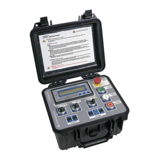
SYNCONpanel - Transportable Remote Synchronizing Panel SYNCONpanel ≡≡≡≡≡≡≡≡≡≡≡≡≡≡≡≡≡≡≡≡≡≡≡≡≡ The SYNCONpanel consists of the SYNCON unit described under SYNCON Unit on page 14 and various con- trol switches and buttons as well as measuring inputs. Figure 5-2: SYNCONpanel front Push Buttons The following push buttons are utilized to remote control the synchronization process on the SYNCONpanel. -
Page 19: Selector Switches
Busbar Sensing Busbar sensing selection Local..The busbar voltage is measured via the voltage measur- ing inputs on the front of the SYNCONpanel. Remote ..The busbar voltage is measured via the industrial plug-in connector. The measuring inputs on the front of the SYNCONpanel (Busbar L1 and Neutral N) are discon- nected. -
Page 20: Chapter 6. Configuration
SYNCONpanel - Transportable Remote Synchronizing Panel Chapter 6. Configuration NOTE When using the SYNCONpanel together with the GCP-31/RPQ+SC08, it is not possible to configure and control the GCP-31/RPQ+SC08 remotely using LeoPC1 via CAN connection. It is required to configure the unit via LeoPC1 and a DPC connection. -
Page 21: Figure 6-2: Voltage Controller Droop Characteristic
Manual 37187A SYNCONpanel - Transportable Remote Synchronizing Panel Voltage Controller In case of transfer operation mode, the unit controls frequency and voltage with droop behavior. For the transfer operation mode, a droop characteristic for the voltage controller is required, otherwise the gen- erator set would not be able to maintain a stable reactive power being in parallel with the mains. -
Page 22: Automatic Mode Configuration
Manual 37187A SYNCONpanel - Transportable Remote Synchronizing Panel Automatic Mode Configuration Start in mode: STOP, MANUAL, AUTOMATIC, as before Power On Mode: STOP STOP....The unit is in STOP operating mode after applying battery voltage. MANUAL ..The unit is in MANUAL operating mode after applying battery volt- age. -
Page 23: Discrete Input Configuration
Manual 37187A SYNCONpanel - Transportable Remote Synchronizing Panel Mains connection detection (time) 0 to 999 s Detection Mains conn. after 000s If the phase angle between busbar and mains is below the angle configured above for at least the time configured here, the unit detects the connection between busbar and mains and indicates this with the message "Mains connected". -
Page 24: Chapter 7. Operation With The Gcp-31/Rpq+Sc08
8. After starting the engine successfully, the generator can be synchronized with the busbar by pressing the "GCB ON" button on the GCP. With the feedback of a closed GCB, the "Ready" LED at the SYNCONpanel should light up, otherwise the SYNCONpanel is not in operation. -
Page 25: Synchronizing The Consumer Load Back From Generator To Mains
Synchronizing the Consumer Load Back from Generator to Mains 1. If not already done, connect the SYNCONpanel with the container and use the flat bar clamps for voltage measuring. The clamp-on transducer is not required, but if the connection with the mains is expected to take longer, it is recommended to use a clamp-on transducer here as well (the correct polarity must be observed). -
Page 26: Appendix A. Technical Data
Manual 37187A SYNCONpanel - Transportable Remote Synchronizing Panel Appendix A. Technical Data Measuring values, voltages ---------------------------------------------------------------------------------- Busbar measuring input: front / back switchable Mains measuring input: front Front measuring inputs with internal fuse 5x20 mm 5 A slow-to-blow Rated measuring voltage (V ) ................230 Vac... - Page 27 Phone +49 (711) 789 54-0 • Fax +49 (711) 789 54-100 sales-stuttgart@woodward.com Homepage http://www.woodward.com/power Woodward has company-owned plants, subsidiaries, and branches, as well as authorized distributors and other authorized service and sales facilities throughout the world. Complete address/phone/fax/e-mail information for all locations is available on our website (www.woodward.com).
Need help?
Do you have a question about the SYNCONpanel and is the answer not in the manual?
Questions and answers