
Related Manuals for Woodward AtlasSC 8273-040


Summary of Contents for Woodward AtlasSC 8273-040
- Page 1 Released Product Manual 26179 (Revision J, 7/2017) Original Instructions AtlasSC™ Digital Control Control Part Numbers 8273-040, -041, -042, -043 Installation and Operation Manual...
- Page 2 Revisions— A bold, black line alongside the text identifies changes in this publication since the last revision. Woodward reserves the right to update any portion of this publication at any time. Information provided by Woodward is believed to be correct and reliable. However, no responsibility is assumed by Woodward unless otherwise expressly undertaken.
-
Page 3: Table Of Contents
Automation Direct Discrete Output (Sink) (T1K-16TD1) Module ..........102 Automation Direct Relay Output (T1K-08TRS) Module ............104 Automation Direct Analog Input (T1F-16AD-1) Module ............106 Automation Direct Analog Output (T1F-16DA-1) Module ............108 Automation Direct Thermocouple Input (T1F-14THM) Module ..........113 Woodward... - Page 4 Product Service Options ......................127 Returning Equipment for Repair ....................128 Replacement Parts ........................129 Engineering Services ........................ 129 Contacting Woodward’s Support Organization ................. 129 Technical Assistance ........................ 130 A........................131 PPENDIX ................131 CRONYMS AND...
- Page 5 Figure 6-12. Voltage Bias Output Interface to the PowerSense Board ............77 Figure 6-13. Voltage Bias Output Interface to the PowerSense Board ............77 Figure 6-14. LON Interface to the PowerSense Board ................78 Figure 7-1. 12-Channel Relay Module ......................81 Woodward...
- Page 6 Table 4-4. Analog Inputs ..........................29 Table 4-5. Analog Outputs .......................... 29 Table 4-6. Actuator Outputs ........................30 Table 4-7. Discrete Inputs ........................... 30 Table. 4-8. Serial I/O ........................... 30 Table 4-9. Serial Cable Requirements ......................37 Woodward...
- Page 7 Table 9-3. Modbus Slave Exception Error Codes ..................119 Table 9-4. Modbus Communication Port Adjustments ................119 Table C-1. SmartCore Failure Codes ....................... 137 Table C-2. Analog Combo Failure Codes ....................137 Table C-3. PowerSense Failure Codes ....................137 Woodward...
-
Page 8: Warnings And Notices
Be prepared to make an emergency shutdown when starting the engine, turbine, or other type of prime mover, to protect against runaway or overspeed with possible personal injury, loss of life, or property damage. Start-up Woodward... -
Page 9: Electrostatic Discharge Awareness
Do not touch the components or conductors on a printed circuit board with your hands or with conductive devices. To prevent damage to electronic components caused by improper handling, read and observe the precautions in Woodward manual 82715 , Guide for Handling and Protection of Electronic Controls, Printed Circuit Boards, and Modules. -
Page 10: Regulatory Compliance
Division 2 applications. RISQUE D’EXPLOSION—Ne pas raccorder ni débrancher tant que l’installation est sous tension, sauf en cas l’ambiance est décidément non dangereuse. La substitution de composants peut rendre ce matériel inacceptable pour les emplacements de Classe I, Division 2. Woodward... - Page 11 It is recommended that operation of such devices be kept more than 3 m from the AtlasSC control. This will prevent any degradation. Installation of the unit in a metal enclosure will also prevent degradation. Woodward...
-
Page 12: Chapter 1. General Information
Once the application program has been generated and loaded into the AtlasSC control, the user can view variables and tune the control with the Woodward Watch Window Standard service tool. Connection to other devices, such as an HMI, is accomplished by means of serial Modbus ®... -
Page 13: Control Accessories
Figure 1-1. AtlasSC Module Layout Control Accessories The AtlasSC digital control is designed to interface with the Woodward Watch Window Standard and Watch Window Professional service tools. Watch Window is a configuration and troubleshooting tool that provides a window into the control system. It runs on a PC and is connected to a serial communication port on the AtlasSC control. -
Page 14: Figure 1-2. Atlassc Control Layout
Released Manual 26179 AtlasSC™ Digital Control Figure 1-2. AtlasSC Control Layout Woodward... -
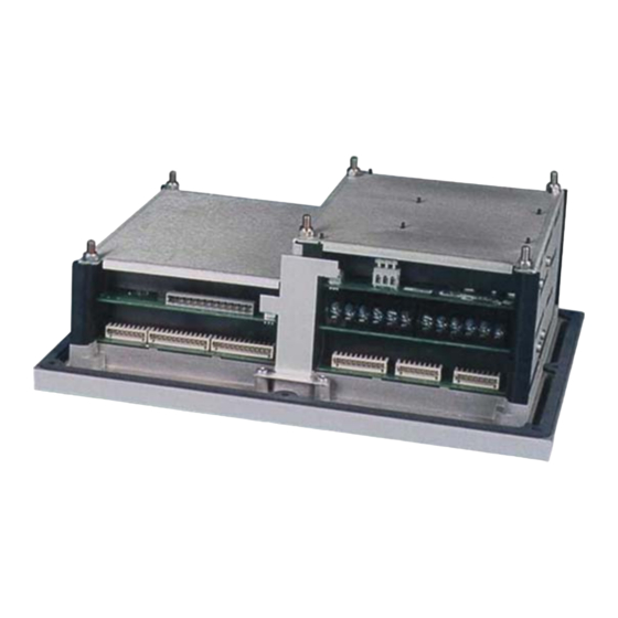
Page 15: Figure 1-3. Atlassc Control (8273-040)
Released Manual 26179 AtlasSC™ Digital Control Figure 1-3. AtlasSC Control (8273-040) Woodward... -
Page 16: Figure 1-4. Atlassc Control (8273-041)
Released Manual 26179 AtlasSC™ Digital Control Figure 1-4. AtlasSC Control (8273-041) Woodward... -
Page 17: Figure 1-5. Atlassc Control (8273-042)
Released Manual 26179 AtlasSC™ Digital Control Figure 1-5. AtlasSC Control (8273-042) Woodward... -
Page 18: Figure 1-6. Atlassc Control (8273-043)
Released Manual 26179 AtlasSC™ Digital Control Figure 1-6. AtlasSC Control (8273-043) Woodward... -
Page 19: Chapter 2 Installation
The AtlasSC Control Platform operates in a specified ambient temperature of –20 to +70 °C (–4 to +158 °F). Continuous operation with insufficient airflow or higher operating temperatures will lead to reduced reliability and possible damage to the control. Woodward... -
Page 20: Figure 2-1. Spring Clamp
The AtlasSC fixed terminal blocks used for the power supply input accept wires from 0.08–1.1 mm² (28– 18 AWG). Two 0.5 mm² (20 AWG) wires or three 0.3 mm² (22 AWG) wires can be easily installed in each terminal. Wires for the fixed mounted power terminals should be stripped 5 mm (0.2 inch). Woodward... -
Page 21: Figure 2-2. Wiring Fixed Terminal
This connection will be made using a thread- forming screw (M4 x 6 mm). The conductor providing the connection shall have a properly sized ring lug and wire larger than or equal to 3.3 mm² (12 AWG). Woodward... - Page 22 500 V capacitor is sufficient. The intent is to provide a low impedance path to earth for the shield at frequencies of 150 kHz and up. Multiple direct connections of a shield to earth risk high levels of current to flow within the shield. See Woodward application note 50532, Interference Control in Electronic Governing Systems, for more information.
- Page 23 Significant inrush currents are possible when current is applied to the AtlasSC control. The magnitude of the inrush current depends on the power source impedance, so Woodward cannot specify the maximum inrush current. Time-delay fuses or circuit breakers must be used to avoid nuisance trips.
-
Page 24: Figure 2-4. Input Power Wiring Diagram
0.16 volts. The resulting supply voltage from the example must be greater than 18.16 volts. Input Power Wiring Diagram The power supply and ground connections are located on the power supply board. AtlasSC Power Supply Board Optional Common System Ground Switching Power Supply Figure 2-4. Input Power Wiring Diagram Woodward... -
Page 25: Chapter 3. Power Supply Board
This equipment is suitable for use in Class 1, Division 2, Groups A, B, C, and D, or non-hazardous locations only. Wiring must be in accordance with Class I, Division 2 wiring methods and in accordance with the authority having jurisdiction. 855-741C 02-11-21 Figure 3-1. Power Supply Board (601-1008) Woodward... -
Page 26: Specifications
Troubleshooting Guide Power Supply Checks The following is a troubleshooting guide for checking areas, which may present difficulties. If these checks are made prior to contacting Woodward for technical assistance, system problems can be more quickly and accurately assessed. ... -
Page 27: Figure 3-2. Discrete Output Wiring Example
(Discrete Output power input current plus 12 times the maximum Discrete Output channel current) shall be provided. Fuse current rating should not exceed 6.25 A (time delay fuses are recommended). Chapter 7 describes a relay module that can be used with these discrete outputs. Woodward... -
Page 28: Chapter 4. Smartcore Board With Actuators
±0.08% full scale from –40 to +85 °C internal temperature Table 4-2. MPU Inputs Minimum input See Figure 4-2 amplitude Input amplitude 70 V peak-to-peak Input impedance >1.5 kΩ Isolation voltage 500 Vac minimum, each channel is isolated from all other channels and from the AtlasSC platform Woodward... -
Page 29: Figure 4-1. Smartcore Board With Actuators Connections
Released Manual 26179 AtlasSC™ Digital Control 855-742A 02-6-17 Figure 4-1. SmartCore Board with Actuators Connections Woodward... -
Page 30: Figure 4-2. Minimum Mpu Voltage Graph
No proximity probe power provided. If the proximity probe inputs are used, the corresponding MPU inputs must be jumpered. 10000 15000 20000 25000 30000 Frequency (Hz) Figure 4-2. Minimum MPU Voltage Graph Woodward... - Page 31 Max load resistance 300 Ω at 22 mA Resolution 12 bits Accuracy @ 25 °C less than ±0.1% of full scale, 0.025 mA Temperature Drift 140 PPM/°C, 0.23 mA maximum 70 ppm/°C, typical (0.45% of full scale, 0.11375 mA) Woodward...
- Page 32 1 - RS-232, 9 pin sub D connector configuration 2 - RS-232/RS-485/RS-422 software configurable, terminal block connections Termination Resistor Located on the board and are accessible via field wiring. Termination resistors are provided for RS-485 and RS-422 Receive. Isolation Voltage 500 Vdc Woodward...
-
Page 33: Smartcore Board Operation
For safety purposes, it is also not recommended that the speed sensing device sense speed from a gear coupled to a generator or mechanical drive side of a system’s rotor coupling. Atlas Passive (isol) Figure 4-3. MPU Interface to the SmartCore Board (wiring example) Woodward... -
Page 34: Figure 4-4. Proximity Probe To The Smartcore Board
All Analog inputs have 10 Vdc of common mode rejection. If interfacing to a non- isolated device, which may have the potential of reaching over 10 Vdc with respect to the control’s common, the use of a loop isolator is recommended to break any return current paths, which could produce erroneous readings. Woodward... -
Page 35: Figure 4-5A. 4-20 Ma Input Interface To The Smartcore Board
Figure 4-5a. 4–20 mA Input Interface to the SmartCore Board (wiring example) (+) Loop Power Atlas 100 mA Fuse 4-20 mA Transducer Loop Powered (-) Loop Power Figure 4-5b. 4–20 mA Input Interface using External Loop Power (wiring example) Woodward... -
Page 36: Figure 4-6. 0-5 V Input Interface To The Smartcore Board
Analog Outputs The analog outputs are 4–20 mA with a full scale range of 0–24 mA. The SmartCore board has four analog outputs. Atlas +15 Vdc 4-20 mA Figure 4-7. Analog Output Interface to the SmartCore Board (wiring example) Woodward... -
Page 37: Figure 4-8. Actuator Output Interface To The Smartcore Board
Application software selects the actuator type, the output range, and the dither amount. The readbacks can be used in the application software for fault detection. Avoid misconnection of the Analog Output (+) to the Actuator Output (–). This will damage internal components, making the control inoperable. Woodward... -
Page 38: Figure 4-9. Discrete Input Interface To The Smartcore Board
(15 m/50 ft). In practice, the standard is largely ignored beyond the most rudimentary implementation of electrical signals (±3 to ±15 volts). Woodward’s implementation will support speeds up to 115K baud in Atlas systems. The actual specification allows 19.2K baud at up to 15 m (50 ft). - Page 39 6.0 dB maximum Recommended Bulk Cable For simplicity, Woodward will recommend cables consistent with long cable lengths and high baud rates. Longer cable lengths may be possible at lower baud rates with the best cables but are not supported by the ANSI standards for RS-485.
-
Page 40: Serial I/O Ports
Devices connected to the opposite end of the cable must provide for the ac-coupled shield connection. Woodward has found that a 0.01 µF capacitance is typically adequate for this purpose. A minimum rating of 1000 Vdc on the capacitor is required. -
Page 41: Figure 4-10. Rs-232 Interface To The Smartcore Board
Fiber optic cable with optical repeaters > 150 m (500 ft) Figure 4-10. RS-232 Interface to the SmartCore Board (wiring example) Figure 4-11. RS-422 Interface to the SmartCore Board (wiring example) Figure 4-12. RS-485 Interface to the SmartCore Board (wiring example) Woodward... -
Page 42: Configurable Port (Com 1)
Configurable Port (Com 1) This port may be configured to use the MODBUS RTU protocol or Woodward’s ServLink protocol. The port configuration is defined in the GAP program and sets configuration for kbps, parity, data, and stop bits. -
Page 43: Figure 4-14. Rs-422 Wiring Diagram (Com 1)
AtlasSC™ Digital Control Wiring Diagram—RS-422 (Com 1) Serial #1 - RS-422 Atlas RS 422 Transceiver 422R 422T Twisted Pairs 422R 422T RS 422 Device Isolated Jumpers to use optional termination resistor Isolated Ground Figure 4-14. RS-422 Wiring Diagram (Com 1) Woodward... -
Page 44: Figure 4-15. Rs-485 Wiring Diagram (Com 1)
Isolated Jumpers to use optional termination resistor Isolated Ground Figure 4-15. RS-485 Wiring Diagram (Com 1) Wiring Diagram—RS-232 (Com 1) Atlas Isolated RS 232C Isolated Transceiver Ground Twisted Pair RS 232 Device Figure 4-16. RS-232 Wiring Diagram (Com 1) Woodward... -
Page 45: Figure 4-17. Rs-422 Wiring Diagram (Com 2)
Wiring Diagram—RS-422 (Com 2) Serial #2 - RS-422 Atlas RS 422 Transceiver 422R 422T Twisted Pairs 422R 422T RS 422 Device Isolated Jumpers to use optional termination resistor Isolated Ground Figure 4-17. RS-422 Wiring Diagram (Com 2) Woodward... -
Page 46: Configuration Port (Com 3)
Since this port is the only one that can be used to download application code, we recommend that this port be used only as a Woodward ServLink port. Its primary purpose is for configuration using a PC with Woodward’s Watch Window. However, it may also be connected to a PC based HMI for local configuration and monitoring. -
Page 47: Figure 4-20. Rs-232 Wiring Diagram (Com 3)
RAM Error Watchdog Timeout EEPROM Error FLASH Memory Error Operating System Error Stack Memory Overflow Application Checksum Error Communication Error (68302 Fail) Real Time Clock Error Rate Group Slip Error 13-15 Unused Data Log Error NV Log Error Math Exception Woodward... - Page 48 4–20 mA input, check for proper jumper installation on the terminal block. If all of the inputs are reading high, check that the power is not connected across the input directly. Check the software configuration to ensure that the input is configured properly. Woodward...
- Page 49 Check the software configuration to ensure that the input is configured properly. Check that the cable is shielded and the shield is properly grounded per the shields and grounding section in Chapter 2. After verifying all of the above, the AtlasSC should be returned for service. Woodward...
-
Page 50: Chapter 5. Analog Combo Board
Figure 5-1. Analog Combo Board Connections Physical The AtlasSC Analog Combo board connects to the CPU board through the PC/104 bus. It does not connect to the AtlasSC power bus directly, it requires a SmartCore board for this purpose. Woodward... - Page 51 Combo cards from 410 MHz to 450 MHz at field strengths greater than 10 V/m. Fields of 10–20 V/m degrade the steady-state performance from a 0.1% tolerance to a 0.36% tolerance. Installation of the Atlas in a metal cabinet will minimize this degradation. Woodward...
- Page 52 –80 dB minimum for analog inputs –96 dB typical for analog inputs Common mode rejection –96 dB minimum for RTD inputs –115 dB typical for RTD inputs Input common mode range ±11 V minimum Safe input common mode volt ±40 V minimum Woodward...
- Page 53 500 Vac, each channel is isolated from all other channels, and from Isolation voltage the AtlasSC platform Resolution dependent on frequency, 13 bit minimum at maximum speed Accuracy less than ±0.08% of full scale from –40 to +85 °C internal temperature Woodward...
-
Page 54: Figure 5-2. Minimum Mpu Voltage
0–1 mA OUTPUTS ARE NOT SUPPORTED, WITHOUT A GREATER THAN 4 BIT LOSS OF RESOLUTION. RESULTING RESOLUTION WOULD BE 7 BITS. Common mode voltage is 15 Vdc. Maximum wire size, one 16 AWG (1.5 mm²), or two 20 AWG (0.5 mm²) wires. Woodward... -
Page 55: Figure 5-3. Mpu Interface To The Analog Combo Board
This allows the Analog Combo card to use the applicable hardware calibration values, and to configure the appropriate hardware gains. The first 10 inputs must be configured in pairs, that is, channels 1 and 2 must both be thermocouples or must both be 4–20 mA inputs. Channels 11–15 may be configured individually. Woodward... -
Page 56: Figure 5-4A. 4-20 Ma Or Thermocouple Input Interface To The Analog Combo Board
Figure 5-4a. 4–20 mA or Thermocouple Input Interface to the Analog Combo Board (wiring example, inputs 1–11) (+) Loop Power Atlas 100 mA Fuse 4-20 mA Transducer Loop Powered (-) Loop Power Figure 5-4b. 4–20 mA Input Interface using External Loop Power (wiring example, inputs 1–11) Woodward... -
Page 57: Figure 5-5. 4-20 Ma Input Interface To The Analog Combo Board
The application software must be configured to match the input type used, that is, 4–20 mA, 100 Ω RTD, k-type thermocouple, etc. External loop powered transducers must be individually protected with a 100 mA fuse on each channel. RTDs Only 100 and 200 Ω RTDs are supported. Woodward... -
Page 58: Figure 5-7. Analog Output Interface To The Analog Combo Board
The output does not contain fault detection. If it is necessary to detect failures, then the device that is driven by the Analog output, for example an actuator driver, must contain reference failure detection. The Analog outputs have a 15 V common mode voltage, with respect to AtlasSC control common. +V is 15 V Woodward... - Page 59 Analog Combo board may be faulty or may have the address DIP switches configured incorrectly. The DIP switch setting must match the module address set in the GAP application program. Woodward...
-
Page 60: Troubleshooting Guide
Check the wiring. Look for a loose connection at the terminal blocks and disconnected or misconnected cables. Check the software configuration to ensure that the input is configured properly; check the hertz to rpm ratio, and the maximum speed. After verifying all of the above, the AtlasSC should be returned for service. Woodward... - Page 61 Disconnect the field wiring and connect a resistor across the output. If the output is correct across the resistor, there is a problem with the field wiring. Check the software configuration to ensure that the input is configured properly. After verifying all of the above, the AtlasSC should be returned for service. Woodward...
- Page 62 HIGH VOLTAGE—To prevent risk of electric shock, make sure that the terminal block covers are installed on the above inputs before operation (see Figure 6-1). Woodward...
-
Page 63: Figure 6-1. Terminal Block Covers
These inputs and outputs are provided with 500 V of dielectric isolation from chassis ground. In addition, these inputs/outputs are isolated from safety extra-low voltage (SELV) circuits (such as serial communication, PC/104 circuits) by optoisolators or transformers provided with double insulation and 3 kVac of dielectric isolation. Woodward... -
Page 64: Figure 6-2. Powersense Board Connections
Released Manual 26179 AtlasSC™ Digital Control Figure 6-2. PowerSense Board Connections Woodward... - Page 65 Any 40 °C change CT Temp Drift Typical (1σ): < 0.4% or 20.0 mA < 0.3% or 15.0 mA Max (3σ): < 1.2% or 60.0 mA < 0.8% or 40.0 mA Input Impedance 0.030 Ω Isolation see HAZARDOUS LIVE section above Woodward...
- Page 66 Options: 4–20 mA, ±1V, ±3V, ±9V; software and wiring selectable. Both the GAP block field and the wiring must be changed to switch between current and voltage outputs. Only the GAP block field must be changed to switch between the voltage outputs. Woodward...
- Page 67 0.5% or 1.2 V, 240 Vac scale Typical Temperature <0.4% of Vrange for any 40 °C Drift for voltage inputs change Typical Temperature <0.4% or 20.0 mA for any 40 °C Drift for current inputs change * Accuracy values at 25 °C with no harmonics Woodward...
- Page 68 PT and CTs, it is not possible to configure the PTs for “Y”, and the CTs for “delta”, or vice versa. However, the configuration may differ between PT/CT 1 and PT/CT 2 (or gen and mains in a typical configuration). Woodward...
-
Page 69: Figure 6-3. Wye Connected System
Released Manual 26179 AtlasSC™ Digital Control AtlasPC PH A PH B PH C Load Bus PH A PH B PH C VIS-152a 01-4-26 Figure 6-3. Wye Connected System (wiring example, PT Interface wired L-N to the PowerSense Board) Woodward... -
Page 70: Figure 6-4. Wye Connected System
Load Bus PH A PH B PH C VIS-152b 01-4-26 Figure 6-4. Wye Connected System (wiring example, wired L-N to PowerSense with potential transformers used to step the voltage down to a level within the capability of the PowerSense inputs) Woodward... -
Page 71: Figure 6-5. Wye Connected System
01-4-26 Figure 6-5. Wye Connected System (wiring example, wired L-L to PowerSense with potential transformers used to step the voltage down to a level within the capability of the PowerSense inputs; the ground on the b-phase input is optional.) Woodward... -
Page 72: Figure 6-6. Delta Connected System
Released Manual 26179 AtlasSC™ Digital Control AtlasPC PH A PH B PH C Load Bus PH A PH B PH C VIS-152d 01-4-26 Figure 6-6. Delta Connected System (wiring example, PT Interface wired L-L to the PowerSense Board) Woodward... -
Page 73: Figure 6-7. Delta Connected System
01-4-26 Figure 6-7. Delta Connected System (wiring example, wired L-L to PowerSense with potential transformers used to step the voltage down to a level within the capability of the PowerSense inputs; the ground on the B-phase input is optional.) Woodward... - Page 74 The application software must configure the PT/CT block for the correct system frequency 50 Hz, or 60 Hz, as well as for the correct rotation, clockwise or counterclockwise. See the GAP help, for information on application software configuration variables. The terminal block screws should be torqued to 8–10 lb-in (0.9–1.1 Nm). Woodward...
- Page 75 PowerSense should also be Delta connected (line-to-line). The “Y” or “delta” configuration applies to the entire set of PT and CTs, it is not possible to configure the PTs for “Y”, and the CTs for “delta”, or vice versa. Woodward...
-
Page 76: Figure 6-8. Ct Interface To The Powersense Board
Released Manual 26179 AtlasSC™ Digital Control AtlasPC PH A PH B PH C Load Bus PH A PH B PH C VIS-152f 01-4-26 CT grounds optional Figure 6-8. CT Interface to the PowerSense Board (wiring example) Woodward... -
Page 77: Figure 6-9. Ct Interface To The Powersense Board
Released Manual 26179 AtlasSC™ Digital Control AtlasPC PH A PH B PH C Load Bus PH A PH B PH C VIS-152g 01-4-26 CT grounds optional Figure 6-9. CT Interface to the PowerSense Board (wiring example) Woodward... -
Page 78: Figure 6-10. Speed Bias Output Interface To The Powersense Board
Figure 6-10. Speed Bias Output Interface to the PowerSense Board (wiring example, configured for 4–20 mA) Atlas Speed Bias ±3, 0-5, PWM interface to speed control (isol) Figure 6-11. Speed Bias Output Interface to the PowerSense Board (wiring example, configured for ±3 V, 0–5 V, or PWM) Woodward... -
Page 79: Figure 6-12. Voltage Bias Output Interface To The Powersense Board
(wiring example, configured for 4–20 mA) Atlas Voltage Bias ±1, ±3, ±9 V interface to voltage regulator (isol) Figure 6-13. Voltage Bias Output Interface to the PowerSense Board (wiring example, configured for ±1 V, ±3 V, or ±9 V) Woodward... -
Page 80: Figure 6-14. Lon Interface To The Powersense Board
The LON channel is DSLC/MSLC and EGCP-3 compatible. It may only be used with specified Woodward equipment. Fault Detection (Board Hardware) Each PowerSense board has a red fault LED that is turned on when the system is reset. During initialization of a board, which occurs after every CPU reset, the CPU turns the Fault LED on. -
Page 81: Troubleshooting Guide
If the CT common is not grounded, try grounding it to eliminate offsets in the readings. Be sure to ground it in the same location as the other system grounds following good, accepted grounding practices. After verifying all of the above, the AtlasSC should be returned for service. Woodward... - Page 82 The cable length should not exceed the maximum allowed cable length. Check to make sure that termination networks are installed on the ends of the network. Check the software configuration. After verifying all of the above, the AtlasSC should be returned for service. Woodward...
-
Page 83: Chapter 7. 12-Channel Relay Module
The Atlas system has 12 relay drivers on the power supply board. For customers that do not wish to wire their own discrete relays, Woodward can provide an integrated 12-channel relay module with cable harness that is certified for use in ordinary, hazardous, and marine locations. -
Page 84: Shielding
Atlas power supply board. Refer to the following plant wiring diagram and the power supply chapter of this manual for more details. Woodward... -
Page 85: Figure 7-2. 12-Channel Relay Module Connections
Released Manual 26179 AtlasSC™ Digital Control Figure 7-2. 12-Channel Relay Module Connections Woodward... -
Page 86: Chapter 8. Distributed I/O
(15m/50 ft). In practice the standard is largely ignored beyond the most rudimentary implementation of electrical signals (±3 to ±15 volts). Woodward's implementation will support speeds up to 115K baud in AtlasSC systems. The actual specification allows 19.2K baud at up to 15 m (50 ft). - Page 87 Because it uses balanced drivers, it can communicate over long distances (1200 m/4000 ft) at high baud rates. Woodward's implementation of RS-422 supports data rates up to 115K baud. In addition to the standard RS-422 features, a multidrop function is implemented as well. This allows more than one device to be connected to a common bus (up to 32 devices) with a single master requesting data.
- Page 88 The AtlasSC control system may control Modbus slave modules from many different manufacturers. With the exception of Woodward-manufactured devices, Woodward makes no expressed or implied statement of suitability of these devices. It is the user’s responsibility to ensure EMC compliance of their system, if necessary, by using distributed modules that are CE compliant.
- Page 89 Many end users will be purchasing pre-programmed AtlasSC units and will not need the information in this section. The information below is aimed at programmers using the GAP programming tool provided by Woodward. The information provided here covers the basics. Programmers will need the following: ...
- Page 90 Woodward software interface may differ from vendor to vendor. Due to limited resources, Woodward can only supply limited technical support for those applications using other vendors or part numbers not shown in these examples. If extensive support is required, contact Woodward for setting up an application development contract.
- Page 91 In order to simplify the nomenclature used in creating the GAP application, certain naming conventions were changed with respect to the manufacturer’s naming convention. In this example, Woodward refers to the node address as the Group address. The T1K-MODBUS Group address, (Node address), is set by two rotary switches located on the front of the T1K-MODBUS module.
-
Page 92: Figure 8-1. Automation Direct Terminator I/O Configuration
The E_ERR_1_x output field on the MODBUS_M block is used to display Exception Error on PORT_1 per RPTx. It latches TRUE when an exception error is detected. E_NUM_1_X (hidden) displays the error number. See Table 8-2 for exception errors. Woodward... - Page 93 40002 40003 40004 40030 40031 40032 T1F-14THM 30033 None 30034 30035 30036 30062 30063 30064 Use the following documents from the manufacturer to obtain the Memory Maps and related information. Module Document P/N I/O modules T1K-INST-M Modbus Interface T1K-MODBUS-M Woodward...
- Page 94 In this example, the TIK-MODBUS adapter is configured for the 584 / 984 Addressing mode (Dip switch 7). See Figure 8-3, for the full T1K-MODBUS adapter addressing table. Woodward...
-
Page 95: Figure 8-3. T1K-Modbus Adapter Addressing Table
The S_ADD_1 field must agree with the Group or Node address for the T1K-MODBUS adapter. In this example, the address is set to 01 which matches the two rotary switch settings on the adapter. See Figure 8-4 for example of MODBUS_M repeat fields. Woodward... -
Page 96: Figure 8-4. Modbus_M Block Rpt Example
MODBUS_M block by applying this formula. See Figures 8-5, 8-6, 8-7, and 8-8 for all read/write address windows. Figure 8-5 shows the write addresses for the discrete output modules (T1K-16TD1 and T1K- 08TRS), addresses 00001 to 00024. Figure 8-5. MODBUS_M Block Boolean Write RPT Example Woodward... -
Page 97: Figure 8-6. Modbus_M Block Boolean Read Rpt Example
Example: 2X16 addresses for the T1F-AD-1 module + 2X14 addresses for the T1F-14THM module = 60 addresses total. Figure 8-7. MODBUS_M Block Analog Read RPT Example Figure 8-8 shows all of the used write output addresses for the analog output module (T1F-16DA-1), addresses 40001 to 40032. Woodward... -
Page 98: Automation Direct Modbus Interface (T1K-Modbus) Module
The first word is used, and the second is not used. The unused address must be accounted for when addressing the modules and therefore requires each channel to increment by two addresses. Figure 8-8. MODBUS_M Block Analog Write RPT Example Automation Direct Modbus Interface (T1K-MODBUS) Module Woodward... -
Page 99: Figure 8-9. T1K-Modbus Dip Switch Settings
DB15-12 RTS (-) (RS-422) DB15-13 RXD (+) (RS-422) DB15-14 CTS (+) (RS-422) DB15-15 CTS (-) (RS-422) Figure 8-10. Automation Direct Modbus RS-232 Serial Connection The Automation Direct T1K-MODBUS adapter doesn’t reserve any read or write addresses for status words. Woodward... -
Page 100: Automation Direct Discrete Input (Sink) (T1K-08Nd3) Module
This configuration is set up with jumpers located on the module. See Figure 8-11 for T1K-08ND3 Sink/External Power Configuration. Figure 8-11. T1K-08ND3 Sink/External Power Configuration See Figure 8-12 for example of T1K-08ND3 module wiring. Woodward... -
Page 101: Figure 8-12. T1K-08Nd3 Module Wiring
MODBUS_M block RPT window shown above. See Figure 8-14 for example of T1K-08ND3 Read GAP blocks. From MODBUS_M (Address 10001) From MODBUS_M To GAP Application (Address 10008) Figure 8-14. T1K-08ND3 Read GAP Blocks (example) Woodward... -
Page 102: Automation Direct Discrete Input (Sink) (T1K-16Nd3) Module
This configuration is set up with jumpers located on the module. See Figure 8-15 for T1K-16ND3 Sink/External Power Configuration. Figure 8-15. T1K-16ND3 Sink/External Power Configuration See Figure 8-16 for example of T1K-16ND3 module wiring. Woodward... -
Page 103: Figure 8-16 T1K-16Nd3 Module Wiring
In this example, each bit is displayed using a B_NAME block. Each block is connected to the specific address in the MODBUS_M block RPT window shown above. See Figure 8-18 for example of T1K-16ND3 Read GAP blocks. Woodward... -
Page 104: Automation Direct Discrete Output (Sink) (T1K-16Td1) Module
(Address 10024) Figure 8-18. T1K-16ND3 Read GAP Blocks (example) Automation Direct Discrete Output (Sink) (T1K-16TD1) Module In this example the T1K-16ND3 was connected to a Woodward 16 channel relay module. See Figure 8- 19 for example of T1K-16ND3 module wiring. Woodward... -
Page 105: Figure 8-19. T1K-16Nd3 Module To Relay Module Wiring
Released Manual 26179 AtlasSC™ Digital Control +28VDC TB19 + DISTRIBUTED I/O 28COM TB19 - Woodward Automation Direct T1K-16TD1 +28VDC J1-23 +28VDC J1-24 16 Channel Relay DISCRETE OUTPUT Module 28COM J1-21 Output 0 28COM J1-22 Output P/N 5441-691 Com0-0 Common MBI.A1.A02.G1.N3_BO_01... -
Page 106: Automation Direct Relay Output (T1K-08Trs) Module
Released Manual 26179 AtlasSC™ Digital Control To MODBUS_M (Address 00001) To MODBUS_M From GAP Application (Address 00016) Figure 8-21. T1K-16TD1 GAP Write Blocks (example) Automation Direct Relay Output (T1K-08TRS) Module See Figure 8-22 for example of T1K-08TRS module wiring. Woodward... -
Page 107: Figure 8-22. T1K-08Trs Module Wiring
In this example, each bit is written using a B_NAME block. Each block is connected to the specific address in the MODBUS_M block RPT window shown above. See Figure 8-24 for example of T1K-08TRS write GAP blocks. Figure 8-24. T1K-08TRS GAP Write Blocks Woodward... -
Page 108: Automation Direct Analog Input (T1F-16Ad-1) Module
Common V3-13 Common Supply Voltage 4-20mA Input 14 Input Source MBI.A1.A02.G1.N5_AI_15 Com3-14 Common V3-14 Common Supply Voltage 4-20mA Input 15 Input Source Com3-15 MBI.A1.A02.G1.N5_AI_16 Common To +24VDC V3-15 Common Supply Voltage To 24COM Figure 8-25. T1F-16AD-1 Module Wiring (example) Woodward... -
Page 109: Figure 8-26. T1F-16Ad-1 Analog Input Module Memory Map
(8191). The CURVE_2D X_1 and Y_1 fields have been set up as tunable so that the block can be set for a 4-20mA scale if desired. See Figure 8-28 for example of T1F-16AD-1 GAP CURVE_2D scaling blocks. Figure 8-27. T1F-16AD-1 Current Input Module Resolution Woodward... -
Page 110: Automation Direct Analog Output (T1F-16Da-1) Module
@ 0 Counts (Address 30031) Input Counts @ 20mA mA output @ 8191 Counts Figure 8-28. T1F-16AD-1 GAP CURVE_2D Scaling Blocks (example) Automation Direct Analog Output (T1F-16DA-1) Module See Figure 8-29 for example of T1F-16DA-1 module wiring. Woodward... -
Page 111: Figure 8-29. T1F-16Da-1 Module Wiring
Common V3-13 Common Supply Voltage Output 14 Output 4-20mA Load Com3-14 MBI.A1.A02.G1.N6_AO_15 Common V3-14 Common Supply Voltage Output 15 4-20mA Output Load Com3-15 MBI.A1.A02.G1.N6_AO_16 Common V3-15 To +24VDC Common Supply Voltage To 24COM Figure 8-29. T1F-16DA-1 Module Wiring (example) Woodward... -
Page 112: Figure 8-30. T1F-16Da-1 Module Memory Map
24) is on (True), the polarity is Unipolar (False), the Voltage Range (bit 26) is not needed and therefore set to (False), the Current Range (bit 27) is set for 0–20 mA (False), and bits 28–31 are reserved and therefore set to (False). See Figure 8-32 for T1F-16DA-1 Control Byte Table. Woodward... -
Page 113: Figure 8-31. T1F-16Da-1 Control Byte Table
Released Manual 26179 AtlasSC™ Digital Control Figure 8-31. T1F-16DA-1 Control Byte Table To MODBUS_M (Address 40002) Data Word to be written to Module Figure 8-32. T1F-16DA-1 Control Byte GAP Block (example) Woodward... -
Page 114: Figure 8-33. T1F-16Da-1 Current Output Module Resolution
Figure 8-33. T1F-16DA-1 Current Output Module Resolution Input from GAP To MODBUS_M Application (Address 40001) Minimum Input mA Minimum Output Counts @ Min Input Maximum Input mA From MODBUS_M (Address 30031) Maximum Output Counts @ Max Input Figure 8-34. T1F-16DA-1 GAP Analog Write Blocks (example) Woodward... -
Page 115: Automation Direct Thermocouple Input (T1F-14Thm) Module
Released Manual 26179 AtlasSC™ Digital Control Automation Direct Thermocouple Input (T1F-14THM) Module In this example, Type K thermocouples are used. See Figure 8-35 for example of T1F-14THM module wiring. Woodward... -
Page 116: Figure 8-35. T1F-14Thm Module Wiring
According to Automation Direct, the T1F-14THM module uses the same memory map as the T1F-16AD-1 module. Based on this memory map, there are 64 byte (32 words) addresses and no write byte addresses. See Figure 8-36 for memory map of Automation Direct T1F-14THM Thermocouple module. Woodward... -
Page 117: Figure 8-36. T1F-14Thm Thermocouple Module Memory Map
See Figure 8-37 for T1F-14THM jumper configuration tables. In this example, the jumpers were configured for 14 channels of Type K thermocouples with output in degrees F and calibration disabled. See Figure 8-38 for T1F-14THM jumper locations. Figure 8-37. for T1F-14THM Jumper configuration Tables Woodward... -
Page 118: Figure 8-38. T1F-14Thm Jumper Locations
MODBUS interface module. A divide by 10 block is used to scale the thermocouple inputs. See Figure 8- 39 for example of T1F-14THM GAP DIVIDE Blocks. From MODBUS_M (Address 30033) From MODBUS_M (Address 30057) To GAP Application (Deg F) Figure 8-39. T1F-14THM GAP DIVIDE Blocks (example) Woodward... -
Page 119: Chapter 9. Communications
ASCII mode, each binary character is divided into two 4-bit parts (high order and low order), changed to be represented by a hexadecimal equivalent, then transmitted, with breaks of up to 1 second possible. Because of these differences, data transmission with the ASCII mode is typically slower (see Figure 9-1). Figure 9-1. ASCII/RTU Representation of 3 Woodward... - Page 120 When a Modbus message is received, it is checked for any errors or invalid data. If there is invalid data in the message, an error code is sent back to the master and the control issues an alarm message. The error codes are defined in the following table. Woodward...
- Page 121 These values are set in the GAP program, and the GAP programmer may also make these values tunable if desired. Table 9-4. Modbus Communication Port Adjustments PARAMETER ADJUSTMENT RANGE Baud Rate 110 TO 57600 Parity NONE, ODD, or EVEN Stop Bits 1 TO 2 Driver RS-232, RS-422, or RS-485 Woodward...
-
Page 122: Chapter 10. Programming And Service Tools
Window system. This software runs on a PC that is connected to the control with an RS-232 serial cable. Also running on the same PC is the Woodward ServLink I/O server software that allows Watch Window to access selected application variables that were generated in the GAP™ application program. The details of the specific GAP application programming are beyond the scope of this manual, but Woodward publication number 80018 is available to assist the application engineer in this process. -
Page 123: Loading Watch Window And Servlink On The Pc
Woodward website (www.woodward.com/ic). Alternatively, a Watch Window CD Install Kit may be purchased from your Woodward distributor. Once downloaded, the kit’s Setup.exe program will guide the user through the installation of Watch Window and ServLink software on the PC hard drive. - Page 124 ‘File> Save As’ feature on the PC. Link this name to the control part number as it will only work with that application. For example, if the control part number is 8273-040, one can save the Network Definition file as 8273040.NET. See example below. Do not disconnect the server. Woodward...
- Page 125 4. In the ServLink window there will be another dialog window entitled “your filename.NET”. Unless the user has given the control a serial number (or name) with the SLSN.EXE program, this name will display as “<unidentified>”. The user should note this name. See example below. Woodward...
- Page 126 The following steps are required for this program downloading process. Download the Application File 1. Start the Watch Window program by selecting Start> Programs> Woodward> Watch Window Professional> Watch Window Professional on the PC. Under the title bar in the Explorer section of the screen, a tab with the Network Definition filename and the Control ID will be displayed.
- Page 127 The same procedure that was used initially to create a Network Definition file can be used again. Be sure the engine or turbine is shut down before downloading. Damage to the machine or other serious problems can result if the unit is running during the download procedure. Woodward...
- Page 128 The default installation location can be found by clicking the START icon (Microsoft Windows 95 or later) on the main menu bar and then clicking the PROGRAMS menu item. Look for an icon called WOODWARD WATCH WINDOW. 1. Make sure that all other programs that may access your computer communications port are shut down.
-
Page 129: Chapter 11. Product Support And Service Options
An Authorized Independent Service Facility (AISF) provides authorized service that includes repairs, repair parts, and warranty service on Woodward's behalf. Service (not new unit sales) is an AISF's primary mission. A Recognized Turbine Retrofitter (RTR) is an independent company that does both steam and gas turbine control retrofits and upgrades globally, and can provide the full line of Woodward systems and components for the retrofits and overhauls, long term service contracts, emergency repairs, etc. -
Page 130: Returning Equipment For Repair
All repair work carries the standard Woodward service warranty (Woodward Product and Service Warranty 5-01-1205) on replaced parts and labor. -
Page 131: Replacement Parts
The unit serial number, which is also on the nameplate Engineering Services Woodward offers various Engineering Services for our products. For these services, you can contact us by telephone, by email, or through the Woodward website. Technical Support ... -
Page 132: Technical Assistance
AtlasSC™ Digital Control Technical Assistance If you need to contact technical assistance, you will need to provide the following information. Please write it down here before contacting the Engine OEM, the Packager, a Woodward Business Partner, or the Woodward factory: General... -
Page 133: Ppendix A
Random Access Memory Rate Group. Defines how often software is executed. Resistance Temperature Device Receive Data Line SRAM Static Random Access Memory SSTP Shielded-Shielded Twisted Pair (or Double Shielded Ethernet Cables) Total Harmonic Distortion Transmit Data Line Voltage-to-Current converter Woodward... -
Page 134: Glossary Of Terms
Discrete Output—Output drivers used for driving relays that register only two states, high or low. Serial Port—A connection for RS-232, RS-422, or RS-485. Speed Sensor Input—An MPU or proximity probe input on the SmartCore board, and a MPU only input on the Analog Combo board. Woodward... -
Page 135: Ppendix B
Released Manual 26179 AtlasSC™ Digital Control Appendix B. Wiring Diagrams 855-742A 02-6-17 Figure B-1. SmartCore Board with Actuators Connections Woodward... -
Page 136: Figure B-2. Analog Combo Board Connections
Released Manual 26179 AtlasSC™ Digital Control 855-740 02-2-22 Figure B-2. Analog Combo Board Connections 855-741C 02-11-21 Figure B-3. Power Supply Board Connections Woodward... -
Page 137: Figure B-4. Powersense Board Connections
Released Manual 26179 AtlasSC™ Digital Control Figure B-4. PowerSense Board Connections Woodward... -
Page 138: Figure B-5. 12-Channel Relay Module Connections
Released Manual 26179 AtlasSC™ Digital Control Figure B-5. 12-Channel Relay Module Connections Woodward... -
Page 139: Appendix C. Flash Codes
Kernel Watchdog Timeout System Error Board Identification Error TPU RAM failure Dual Port RAM test failure QSM or ADC Initialization failure Self test status failure Invalid A/D converter selected QSPI timeout ADC auto calibration time-out Table C-3. PowerSense Failure Codes Woodward... -
Page 140: Revision History
Changes in Revision J— Removed reference to Zone 2 and DEMKO certification Removed EMC, Low Voltage Directive, ATEX and DEMKO references Removed European Zone 2 information Removed Zone 2, Group IIC information Deleted DoC Woodward... - Page 141 Email and Website—www.woodward.com Woodward has company-owned plants, subsidiaries, and branches, as well as authorized distributors and other authorized service and sales facilities throughout the world. Complete address / phone / fax / email information for all locations is available on our website.
Need help?
Do you have a question about the AtlasSC 8273-040 and is the answer not in the manual?
Questions and answers