Table of Contents
Advertisement
Quick Links
Advertisement
Table of Contents

Subscribe to Our Youtube Channel
Related Manuals for Maipu MP3900X Series

Summary of Contents for Maipu MP3900X Series
- Page 1 MP3900X Series Router Installation Manual V1 .1...
- Page 3 This Manual may be subject to changes on account of product upgrade or other causes. Maipu reserves the right to revise this Manual without any notice. Subject to the laws and regulations, Maipu Communication Technologies Co., Ltd. shall, under no circumstance,...
- Page 4 Preface Manual Introduction This manual introduces the appearance, hardware, and installation preparation and method of the MP3900X series router, as well as its basic use and daily maintenance in terms of energization & operation, troubleshooting and equipment maintenance. Product Version This manual is applicable to the product versions as below.
- Page 5 MP3900X Series Router Installation Manual Preface Convention of icons and signs Format Description Supplement to or emphasis on the aforesaid. Note: Matters that need attention while installing or operating the equipment, which are important for proper installation and Caution: operation.
- Page 6 Preface MP3900X Series Router Installation Manual Manual Description MP3900X Series Router Detailed introduction to the methods and steps of Configuration Manual configuring the equipment software functions, with the typical cases made available for reference. Technical Support ⚫ Technical support hotline: 400-65710935 & 400-886-8669 ⚫...
-
Page 7: Table Of Contents
MP3900X Series Router Installation Manual Preface Contents PREFACE · · · · · · · · · · · · · · · · · · · · · · · · · · · · · · · · · · · · · · · · · · · · · · · · · · · · · · · · · · · · · · · · · · · · · · · · · · · · · · · · · · · · · · · · · · · · · · · · · · · · · · · · · · · · · · · · · II 1 ROUTER INTRODUCTION ·... - Page 8 Preface MP3900X Series Router Installation Manual 3.4.1 I AC P 3-16 NSTALL OWER 3.4.2 (O 3-17 PTIONAL NSTALL IGHTNING ROTECTOR 3.5 I 3-18 NSTALL OWER UPPLY 3.5.1 I 3-18 NSTALLATION REPARATIONS 3.5.2 I 3-18 NSTALL OWER ODULE 3.6 C 3-19...
-
Page 9: Preface
MP3900X Series Router Installation Manual Preface 5.4 G ECHNICAL UPPORT 6 ROUTER MAINTENANCE · · · · · · · · · · · · · · · · · · · · · · · · · · · · · · · · · · · · · · · · · · · · · · · · · · · · · · · · · · · · · · · · · · · · · · · · · · · · · · · · · · · · 6-1 6.1 C... -
Page 11: Router Introduction
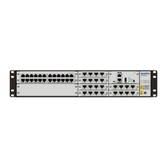
Router Introduction Router Introduction 1.1 MP3900X-08 Appearance and Hardware MP3900X series router only has one product model: MP3900X-08. ⚫ MP3900X-08 router has three kinds of slots: SPU, RM3E, and RM2B. The three slots are respectively inserted with RM3E-SPU card, RM3E-24GETS sub card, and RM2B interface card. - Page 12 Router Introduction MP3900X Series Router Installation Manual 3.RM2B interface card slot 4.MIFC card slot 5. Static wrist socket 6.Chassis air vent Figure 1-2 MP3900X-08 rear appearance 1. Fan slot 2. Power slot 3.SPU card slot 4. Grounding stud 1.2 Introduction to SPU Card SPU card is the core of MP3900X router, which is responsible for packet forwarding and control processing.
- Page 13 MP3900X Series Router Installation Manual Router Introduction ⚫ The SPU card of MP3900X router supports hot-swap. 1.3 Introduction to MIFC Card MIFC card is the management interface card of MP3900X router. The serial port, U disk interface, DC0 port and system status indicator of the device are all on the card.
- Page 14 Router Introduction MP3900X Series Router Installation Manual interface sub card. The 24GETS interface card supports 24 10/100/1000M Ethernet ports, and its main function is to complete data forwarding. Figure 1-5 The appearance of RM3E series card 1. Circuit board component area 2.Scew...
-
Page 15: Introduction Top
MP3900X Series Router Installation Manual Router Introduction 1.6 Introduction to Power Module MP3900X-08 only supports the AC power module. MP3900X-08 supports 1+1 redundant backup of two AC powers. The power module of MP3900X router has the following specification: Specification Description... -
Page 16: Air Passage Of
1.7 Air Passage of MP3900X Series Router The air flow direction of MP3900X series router chassis is left in and right out, and the diagram is as follows: Figure 1-8 Air flow direction of MP3900X series router chassis ⚫... - Page 17 MP3900X Series Router Installation Manual Router Introduction 1. Handle 2. Fan indicator 3.Installation screw of fan card 4.Fan blade 5.Circuit board component area copyright©2020 Maipu, all rights reserved...
-
Page 19: Installation Preparations
Maipu technical staff to replace. 2.1 Check Router Running Environment MP3900X series routers must be used indoors. To ensure the normal running of the router, take the corresponding measures to meet the environment requirement of the router running: ⚫... -
Page 20: Electrical Safety
Installation Preparations MP3900X Series Router Installation Manual ⚫ Keep the router clean and dust-free; do not place the router in the damp place. 2.2.2 Electrical Safety ⚫ Please check whether there are potential dangers. For example, the power is not grounded, power supply grounding is not reliable, and the ground is wet. -
Page 21: Laser Safety
Figure 2-1 Using method of anti-static wrist 2.2.4 Laser Safety ⚫ For the MP3900X series router with the optical interface, avoid directly viewing the laser beam from the optical module inside. Viewing the laser beam from the optical module inside directly may damage your eyes. -
Page 22: Open -Package Andi
⚫ Multimeter 2.4 Open-Package and Inspection MP3900X series router adopts the carton packaging. The package comprises the carton, plastic bags, protection EPE and other packaging materials. The open-package steps are as follows: Step 1: View the carton label, and confirm the router model in the carton. -
Page 23: Router Installation
There is 10cm heat dissipation space around the router. ⚫ Do not place heavy things on the router. 3.1.2 Install Router to Cabinet This section describes how to install the MP3900X series router to the 19-inch standard cabinet. Installation Preparations ⚫... - Page 24 Router Installation MP3900X Series Router Installation Manual section. ⚫ Before installing the slide, please confirm whether the bearing capacity of the slide meets the weight requirements of MP3900X chassis and internal card. Please refer to "Appendix A specifications of complete device and common modules" for the weight of each component.
- Page 25 MP3900X Series Router Installation Manual Router Installation ⚫ To ensure the stability of the cabinet, try to place a heavy and high router below the cabinet. Step 2: Install the slide on the two sides, respectively. The slides installed on the both sides must be at the same height.
- Page 26 Router Installation MP3900X Series Router Installation Manual Figure 3-3 Install the floating nut Install Router to Cabinet ⚫ Before installing the router to the cabinet, ensure that the corresponding positions on the cabinet are installed with slide (tray) and the slide (tray) can support the weight of router and its accessories.
- Page 27 MP3900X Series Router Installation Manual Router Installation Figure 3-4 Install the router to the standard cabinet 1. Load bearing tray 2. Cabinet square hole column 3. Device host ⚫ If the screw hole on the hanging ear cannot align to the floating nut installed on the...
-
Page 28: Ground The Router
Router Installation MP3900X Series Router Installation Manual Figure 3-5 Install the router to the cabinet ⚫ The hanging ear does not bear the weight. Do not bear the router only using a hanging ear without installing the slide (tray). Check the Installation After the router is installed to the cabinet, check the installation based on the following items and ensure all the items are normal. - Page 29 MP3900X Series Router Installation Manual Router Installation ⚫ Please use the ground cable carried by the router. The steps of installing the ground cable are as follows: Step 1: Remove the ground screw on the chassis of the router. Step 2: Bind the wiring terminal of the ground cable carried by the router to the ground screw of the chassis.
-
Page 30: Install Interfaces
Router Installation MP3900X Series Router Installation Manual 3.3 Install Interface Sub Card Components (Optional) If the installed router contains RM2B-4G interface sub card, the USIM card and 4G antenna need to be installed. This chapter takes the installation of RM2B-4G as an example to describe the installation method of USIM card and 4G antenna. - Page 31 MP3900X Series Router Installation Manual Router Installation Figure 3-9 Turn over the buckle Step 4: Insert the USIM card to the buckle. Figure 3-10 Insert the USIM card to the buckle Step 5: Flip down and level the buckle of the inserted USIM card. After the buckle is leveled, push it horizontally in the direction of lock arrow to make the buckle move about 2mm.
-
Page 32: Install 4G Antenna
Router Installation MP3900X Series Router Installation Manual daughter card" for the installation method of interface daughter card. ⚫ When installing the USIM card, pay attention to the insertion direction of the USIM card. The side with missing angle of the USIM card faces out of the board. - Page 33 MP3900X Series Router Installation Manual Router Installation Step 3: Rotate the 4G antenna to the right and tighten it. Figure 3-15 Tighten the 4G antenna Step 4: Pull up the fixed 4G antenna to complete the installation. Figure 3-16 Pull up the 4G antenna Figure 3-17 Complete the installation of 4G antenna ⚫...
-
Page 34: Optional ) Install
Router Installation MP3900X Series Router Installation Manual is the main antenna, and the right is the auxiliary antenna. The main antenna must be installed, and the auxiliary antenna may not be installed. Refer to Figure 3-18 for the diagram of dual-antenna 4G interface sub card. -
Page 35: Optional) Install Port Lightning Protector
MP3900X Series Router Installation Manual Router Installation automatically. 6.Standard socket Connects to the power in the equipment room via the power cable. ⚫ The power SPD is not provided with the router. The user can purchase it as required. ⚫... -
Page 36: Install Power Supply
Router Installation MP3900X Series Router Installation Manual conversion cable on the router is connected to the OUT end). At the same time, observe whether the indicators on the boards are normal. Step 4: Bind the cables tidily using cable ties. -
Page 37: Connect Power Cable
MP3900X Series Router Installation Manual Router Installation Step 2: Push in the power module until the buckle is fastened with the host chassis. The diagram of inserting the power module: Figure 3-20 Insert the power module 3.6 Connect Power Cable 3.6.1 Installation Preparations... -
Page 38: Check After Installation
Router Installation MP3900X Series Router Installation Manual Figure 3-22 Install the power cable Step 3: Fix the tail of the power cable output plug with the anti-stripping to prevent the output plug of the power cable from falling off. Figure 3-23 Install the power cable Step 4: Insert the input plug of the power cable into the power strip. -
Page 39: Power On And Run Router
MP3900X Series Router Installation Manual Power on and Run Router Power on and Run Router 4.1 Log into Router When logging into the router for the first time, you can only log into the router via Console port. This is the most basic mode of logging into the router and also the basis of configuring other login modes. -
Page 40: Set Pc Hyperterminal Parameters
Power on and Run Router MP3900X Series Router Installation Manual Figure 4-1 Console cable For details about the inner signal connection of the Console cables, refer to Appendix E1 Console Cable. Figure 4-2 Connect the router and PC via the Console port ⚫... - Page 41 MP3900X Series Router Installation Manual Power on and Run Router Figure 4-3 “Location information” interface Step 2: Display the following Telephone and Modem interface and click OK. Figure 4-4 The Telephone and Modem interface Step 3: Display the following Connection Description interface, and fill in the name in Name (N), such as test, and click OK.
- Page 42 Power on and Run Router MP3900X Series Router Installation Manual Figure 4-5 “Connection Description” interface Step 4: Display the following Connect to interface, select the serial interface used by the connection in the Connect using, and click OK. Figure 4-6 “Connect to” interface...
- Page 43 MP3900X Series Router Installation Manual Power on and Run Router Figure 4-7 “com* Properties” interface Step 6: Display the following test-HyperTerminal interface, and click Properties. Figure 4-8 “test-HyperTerminal” interface Display the following “test properties” interface, click Setting, select VT100 in Terminal Step 7: emulation, and click OK.
-
Page 44: Power On And Start
Power on and Run Router MP3900X Series Router Installation Manual Figure 4-9 “Test properties” interface Step 8: Display the following test-HyperTerminal interface, press Enter at the blank place, and the serial port displays the print information. The setting of the HyperTerminal is complete. - Page 45 **************************************************************************** MyPower (R) Operating System Software MP3900X-08(V1) system image file (flash0: /flash/rp39-7.3.2.75(R).pck), version 7.3.2.75(R)(integrity), Compiled on Sep 29 2017, 08:45:29 Copyright (C) 2014 Maipu Communication Technology Co., Ltd. All Rights Reserved. System ID : 00017affffff Hardware Model : MP3900X-08(V1) with 2048 MBytes SDRAM, 8192 MBytes flash...
-
Page 46: Check After Power On
Power on and Run Router MP3900X Series Router Installation Manual 4.1.4 Check after Power on Power on the router. After loading all cards, check as follows to ensure that the later configuration work can be done normally: ⚫ After the router is powered on, the ventilation system works, and check whether there is the sound of the fan rotation and whether there is air discharged from the ventilation holes of the router. -
Page 47: Access Network Via Fiber
Figure 4-11 Appearance of the LC fiber connector Install Optical Module The MP3900X series router supports the SFP optical module and the SFP optical module is installed as follows: ⚫ When installing the SFP module, do not use the hands to touch the gold-finger of the SFP module directly. - Page 48 Power on and Run Router MP3900X Series Router Installation Manual Step 3: Get the SFP module out from the packing box. The appearance of the SFP module is as shown in Figure 4-13. Use the hands to hold the two sides of the SFP module and push...
- Page 49 MP3900X Series Router Installation Manual Power on and Run Router directly. Please install after unplugging the fiber. ⚫ When installing the SFP module, do not use the hands to touch the gold-finger of the SFP module directly. ⚫ The TX wire should be connected to the RX wire of the peer router; the RX wire should be connected to the TX wire of the peer router.
-
Page 50: Hardware Management
This section describes various hardware management functions of the MP3900X series router. With the function interfaces, the user can conveniently view the software and hardware version information of the MP3900X series router, as well as the work status information of the hardware modules. -
Page 51: View Software And Hardware Version Information Of Router
4.3.1 View Software and Hardware Version Information of Router You can use the show version command to view the software and hardware version information of MP3900X series router, including system serial number, hardware general information, hardware version, CPLD version, Monitor version, software version and other information. -
Page 52: View Power Module Status Information
Power on and Run Router MP3900X Series Router Installation Manual Field Description Software Image File Software mirror file name 4.3.2 View Power Module Status Information You can use the show system power command to view the relevant information of the... -
Page 53: View System Environment Temperature Information
You can use the show system fan command to view the information of the fan used on the MP3900X series router, including the fan location information, fan speed, fan work status, swapping times of the fan module, and the error times during swapping. -
Page 54: View Swappable Optical Module Information
Fan-Speed Fan speed percentage 4.3.5 View Swappable Optical Module Information You can use the show optical all command to view the work parameters of all optical modules used on MP3900X series router. Command: router#show optical all Display as follows: Name... - Page 55 MP3900X Series Router Installation Manual Power on and Run Router Field Description module is located VendorName The name of the manufacturer of the optical module LaserWaveLen(nm) The center wavelength of the sent laser Temperature(C) The temperature of the optical module...
-
Page 57: Troubleshooting
MP3900X Series Router Installation Manual Troubleshooting Troubleshooting 5.1 Troubleshooting of Configuration System After the router is powered on and if the system is normal, the start information is displayed on the configuration terminal. If the configuration system fails, there may be no display or messy code on the configuration terminal. -
Page 58: Troubleshooting About Fan
Off: indicates that the fan works abnormally. When the fan indicator on the panel of the MP3900X series router is off, it indicates that the system fan fails. View whether the fans rotate to confirm the faulty fan. Troubleshoot the faults according to the following steps. - Page 59 MP3900X Series Router Installation Manual Troubleshooting are normal. Step 2: Check the connection of the power cable on the power slot of the router. Re-swap the power cable and confirm whether the power cable is loose. Step 3: Replace the power cable connected to the router, and then check whether the power status LED recovers to normal.
- Page 61 Router Maintenance Router Maintenance 6.1 Change Module ⚫ The MP3900X series router supports five types of board cards, SPU card, MIFC card, fan card, RM3E card and RM2B card. ⚫ The MIFC card does not support hot swap. 6.1.1 Change Power Module Preparations before changing Step 1: Wear the anti-static wrist, and make sure the anti-static wrist is reliably grounded.
- Page 62 Router Maintenance MP3900X Series Router Installation Manual Change Power Module The process of replacing the AC power module of MP3900X chassis is as follows: Step 1: Wear anti-static wrist, first press the limit switch as shown in the left figure below, and then pull out the power module as shown in the right figure below.
- Page 63 MP3900X Series Router Installation Manual Router Maintenance Figure 6-3 Pull out the SPU card 1 Step 2: Hold the puller on the SPU card with both hands and turn the puller outward to separate the SPU card from the chassis backplane. The figure below shows the diagram of pulling...
- Page 64 Router Maintenance MP3900X Series Router Installation Manual Figure 6-7 Install the SPU card 2 Step 6: Manually screw in the screws on both sides of the SPU card, and then tighten the screws with a screwdriver to fix the SPU card.
- Page 65 MP3900X Series Router Installation Manual Router Maintenance and go out before the next operation; Figure 6-8 HOT SWAP button Step 2: Use a cross screwdriver to loosen the screws on the interface card to be replaced. Grasp the screws with both hands and pull them outwards to make the interface card separate from the frame panel.
- Page 66 The fan module of MP3900X series router only contains one integral fan module. The replacement steps are as follows: Step 1: Wear an anti-static wrist, and use a cross screwdriver to loosen the upper and lower screws of the fan module.
- Page 67 Router Maintenance Figure 6-12 Insert the fan module to the chassis 6.2 Change Swappable Optical Module MP3900X series router supports the SFP module. The following describes how to change the SFP module. ⚫ When installing or uninstalling the SFP module, do not use the hands to touch the gold-finger part of the SFP module directly.
- Page 68 Router Maintenance MP3900X Series Router Installation Manual Figure 6-14 Install the dust cap of the SFP module Step 4: Up-turn the handle of the installed SFP module to the vertical position to lock the buckle at the top of the module. Use the hands to hold the two sides of the SFP module and...
- Page 69 It is suggested not to insert the SFP module with the fiber into the slot directly. Please first pull out the fiber and then install. 6.3 De-dust the Router This section describes how to de-dust the MP3900X series router. ⚫ The de-dusting mainly refers to the air inlet, outlet, swappable board card, and pigtail of the router.
- Page 70 Router Maintenance MP3900X Series Router Installation Manual module will absorb the dust in the around air. When the amount of the dust reaches a certain degree, the dust will affect the stable running of the fan module and will also be the pollution source of other service boards on the router.
- Page 71 MP3900X Series Router Installation Manual Router Maintenance affected, which further brings potential dangers for the stable running of the router. To ensure the long-term stable running of the router, the maintenance personnel should de-dust all the service boards comprehensively and regularly, once for two years recommended.
- Page 72 Router Maintenance MP3900X Series Router Installation Manual Step 2: Use the dedicated cleaning tools and materials when cleaning the optical interface and pigtail connector. These materials can be purchased from the optical fiber or optical cable manufacturer. ⚫ Use the dust cap to cover the unused optical interfaces on the board and pigtail.
- Page 73 MP3900X Series Router Installation Manual Appendix Appendix A Entire Router and Common Module Specifications A1 Power Consumption/Dimension/Weight Appendix Table A-1 Power consumption/dimension Model Power Consumption Dimension MP3900X-08 Single power 250W 442mm 365mm 88.6mm (W×D×H) (when the whole device is fully loaded with boards, it...
- Page 74 Appendix MP3900X Series Router Installation Manual Model Weight (kg) RM2B-1POS-OC12(V2) 0.12kg RM2B-2SA(V2) 0.14kg RM2B-1SA(V2) 0.12kg RM2B-1CE1(V2) 0.12kg RM2B-1E1(V2) 0.12kg RM2B-4CE1(V2) 0.14kg RM2B-4E1(V3) 0.14kg RM2B-4GET(V1) 0.13kg RM2B-1GE(V1) 0.13kg RM2B-SM1-A(V2) 0.14kg RM2B-1POS-OC3(V2) 0.12kg RM2B-4GEF(V1) 0.13kg RM2B-4G-LTES(V1) 0.18kg RM2B-4G-LTE(V1) 0.18kg RM2B-4G-LTE-A(V1) 0.18kg Appendix Table A-3 The power consumption of the board card...
- Page 75 MP3900X Series Router Installation Manual Appendix Model Power Consumption (W) RM2B-1CPOS-OC3(V2) RM2B-1POS-OC12(V2) RM2B-2SA(V2) RM2B-1SA(V2) RM2B-1CE1(V2) RM2B-1E1(V2) RM2B-4CE1(V2) RM2B-4E1(V3) RM2B-4GET(V1) RM2B-1GE(V1) RM2B-SM1-A(V2) RM2B-1POS-OC3(V2) RM2B-4GEF(V1) RM2B-4G-LTES(V1) RM2B-4G-LTE(V1) RM2B-4G-LTE-A(V1) A2 Specifications of SPU Card SPU card is the most important and necessary board card in MP3900X, which is used for packet forwarding and control processing (MP3900X-08 has and can only be configured with one).
- Page 76 Appendix MP3900X Series Router Installation Manual Appendix Figure A-1 RM3E-SPU03 panel ⚫ RM3E-SPU03 supports 2COMBO+1GEF, only used for MP3900X-08 (V1). The meanings of the RM3E-SPU03 indicators are as follows: Appendix Table A-4 The meanings of the RM3E-SPU03 indicators Name Indicator Color...
- Page 77 MP3900X Series Router Installation Manual Appendix ⚫ RM3E-SPU05 supports 16GET+8GEF, only used for MP3900X-08 (V1). The meanings of the RM3E-SPU05 indicators are as follows: Appendix Table A-5 The meanings of the RM3E-SPU05 indicators Name Indicator Color Status Description Flashing: device selected...
- Page 78 Appendix MP3900X Series Router Installation Manual Name Indicator Color Status Description Flashing: device selected Green Off: device not selected Slowly flashing: indicates that the board is in normal operation state, 0.5Hz. Green Flashing quickly: indicates that the board is in IOS loading state, 5Hz.
- Page 79 MP3900X Series Router Installation Manual Appendix Name Indicator Color Status Description Off: board not loaded SWAP Green On: Board loaded successfully indicator Flashing: board loading/unloading Off: Link interface not connected On: Link interface connected LINK/ACT 0~23 Green Flashing: Link interface has data sent and received There are two types of port indicators: ▲...
- Page 80 Appendix MP3900X Series Router Installation Manual Interface Name Description sending and receiving, only used as network management CONSOLE Configuration port: One RJ45 interface, asyn serial port, default baud rate: 9600bps; One micro USB console interface; Multiplexing mode, auto switching, RJ45 interface preferred.
- Page 81 MP3900X Series Router Installation Manual Appendix Name Indicator Color Status Description to pull out the U disk at this time. Otherwise, the data file in the card will be damaged) On: fan module works normally Green Off: fan module works abnormally...
- Page 82 On: The fan works normally A6 AD250 AC Power Module MP3900X series routers support two modular power slots and two power modules 1 + 1 redundancy backup. For reliability, it is recommended that customers configure two power supplies of the same model.
- Page 83 MP3900X Series Router Installation Manual Appendix Appendix Figure A-7 AD250-1S005E-B power module panel The meanings of the indicators on the AD250-1S005E-B power module are as follows: Appendix Table A-12 The indicators of the AD250-1S005E-B power module Name Indicator Color Status Description...
- Page 84 Appendix MP3900X Series Router Installation Manual B Specifications of General Interfaces B1 10GBase-SR/LR/ER-SFP+ Optical Interface Attributes Appendix Table B-1 10GBase-SR/LR/ER-SFP+ Attribute Description Interface Standard IEEE 802.3ae Interface type SFP+ Work modes 10GBASE-ER 10GBASE-LR 10GBASE-SR 10GBASE-EW 10GBASE-LW 10GBASE-SW 10.3125Gbps(LAN mode) Connector...
- Page 85 MP3900X Series Router Installation Manual Appendix Attribute Description Connection cable Straight-through network cable: C1212-1002 Cross network cable: C1212-1003 B3 1000Base-X-SFP Optical Interface Attributes Appendix Table B-3 1000Base-X-SFP Attribute Description Interface standard IEEE 802.3ab Interface type Work mode 1000Mbps full-duplex Connector...
- Page 86 Appendix MP3900X Series Router Installation Manual B5 CONSOLE Port Attributes Appendix Table B-5 CONSOLE Port attributes Attribute Description Interface standards Asynchronous EIA/TIA-232 Connector type RJ45 Baud Rate 2400bps/4800/9600/19200/38400/115200bps Default value: 9600bps Connect the local terminal (such as PC) and Supported services run the terminal emulation program on the terminal.
- Page 87 MP3900X Series Router Installation Manual Appendix Description Temperature Storage environment temperature -45° C–85° C Work condition 0° C–45° C ⚫ If the temperature is too high, the reliability of the router reduces greatly. The long-time high temperature affects the router life and speeds up the aging of insulation materials.
- Page 88 Appendix MP3900X Series Router Installation Manual electricity appears easily, which harms the circuits on the router. C1.3 Cleanliness Requirements Dust is harmful for the router operation. Dust causes electrostatic absorption, which makes the poor contact of metal connectors. Electrostatic absorption appears especially when the temperature and humidity are lower, which affects the router life and easily causes communication fault.
- Page 89 MP3900X Series Router Installation Manual Appendix C1.4 Anti-Interference Requirement The various interference sources no matter from the exterior of the router or from the interior router affect the router through capacitance coupling, inductance coupling, electromagnetic radiation, public impedance (including grounding system) coupling, and lead (such as power cables, signal lines and output lines).
- Page 90 Appendix MP3900X Series Router Installation Manual larger than the protection switch of the post powered device. The power input range of the router using the AC power is as shown in the following table. Appendix Table C-5 AC power supply requirement...
- Page 91 MP3900X Series Router Installation Manual Appendix D Router Grounding Specifications and Protection D1 Router Grounding Specifications Grounding specifications include general grounding specification, grounding specification for the building of equipment rooms, router grounding specification, communication power grounding specification, signal cable grounding specification, and ground cable laying specification.
- Page 92 Appendix MP3900X Series Router Installation Manual Description The router protection ground (PGND) shall be short-circuited nearby to the protection grounding cooper bar provided by the user, with the short-circuiting cable of the yellow/green plastic insulated copper conducting wire above 35mm...
- Page 93 MP3900X Series Router Installation Manual Appendix Description The DC power shall be added the protection circuit against surge. D1.5 Laying Specifications of Signal Cable The laying specifications of the signal cable are shown in the following table: Appendix Table D-4 The laying specifications of the signal cable...
- Page 94 Appendix MP3900X Series Router Installation Manual Description The length of the protection ground wire should not exceed 45 m, but should be as short as possible. When exceeding 45m, it is required that the consumer re-sets the ground bar nearby.
- Page 95 MP3900X Series Router Installation Manual Appendix ⚫ If using the shielded cable, ensure that the shielded layer well contacts with the metal shell of the router at the router interface. We should install the signal arrester at the corresponding interface of the router after the cable enters the indoor.
- Page 96 Appendix MP3900X Series Router Installation Manual only and you also need to wipe the surface of the peer fiber connector. ⚫ When connecting, you cannot twist or bend the fiber. After installation, the bent radius of the fiber cannot be smaller than 40 mm (In dynamic bending case, the minimum bend radius is 20 D;...
- Page 97 MP3900X Series Router Installation Manual Appendix D2.3 Equipotential Connection Method ⚫ The interconnected routers in the same work range need the equipotential connection. For example, the interconnected routers, the metal sheath of the cable, power supply PE line, and the installed metal structure should ensure the equipotential connection.
- Page 99 Connected to the nine-core serial interface socket of the PC, the console cable of the MP3900X series router is an eight-core unshielded cable. The one side of the cable is the crimping RJ-45 crystal plug and the other side is a DB9 (hole). The view of the console cable is shown in the following figure.
- Page 100 MP3900X Series Router Installation Manual E2 GE Ethernet Interface Cable The GE Ethernet interface cable of the MP3900X series router is an eight-core unshielded twisted cable. Port 1 and port 2, port 3 and port 6, port 4 and port 5, and port 7 and port 8 consist of four pairs of bidirectional receiving and transmitting difference cable pairs.
- Page 101 For the use conditions of the product in the environmental protection use period, refer to the requirements for the use environment in the product manuals. ⚫ In the statement, list all components that may be configured in Maipu products. For the actual components contained in each product, please prevail in kind. ⚫...
Need help?
Do you have a question about the MP3900X Series and is the answer not in the manual?
Questions and answers