Table of Contents
Advertisement
Quick Links
www.ti.com
EVM User's Guide: TMDSCNCD263-PMIC
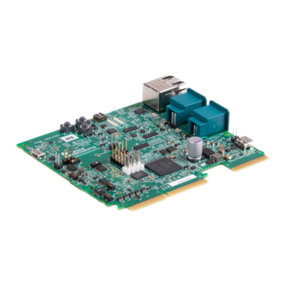
AM263x Control Card with PMIC and Automotive Ethernet
Description
The AM263x Control Card Evaluation Module
(EVM) is an evaluation and development board for
the Texas Instruments Sitara™ AM263x series of
microcontrollers (MCUs). This EVM provides an easy
way to start developing on the AM263x MCUs with
on-board emulation for programming and debugging
as well as buttons and LEDs for a simple user
interface. This version of the AM263x Control Card
(TMDSCNCD263-PMIC) has all of the qualities of
the original AM263x Control Card (TMDSCNCD263)
while also incorporating a PMIC power solution and
replacing two of the Industrial Ethernet PHYs plus
RJ45 connectors with Automotive Ethernet PHYs plus
MATEnet connectors. The control card also enables
header pin access to key signals through the use
of a high speed edge connector (HSEC) baseboard
docking station for rapid prototyping.
Features
•
Integrated power and safety monitoring
solution that is consistent with the ISO26262
ASIL-D specification
– Multirail Power Supply designed for Safety-
Relevant Applications
– Automotive, dual-channel voltage
supervisor with very-high accuracy
SPRUJ93 – AUGUST 2023
Submit Document Feedback
•
Two MATEnet connectors with on-board
Automotive Ethernet PHYs
•
One RJ45 ethernet port with on-board Industrial
Ethernet PHY
•
PCB dimensions: 131.15 mm width by 92.81 mm
length + 6.17 mm length of HSEC interface
•
Powered through 5 V, 3 A USB type-C input
•
On-board XDS110 debug probe
•
180 pin HSEC interface for rapid prototyping
•
Three push buttons:
– PORz
– User interrupt
– RESETz
•
LEDs for:
– Power status
– User testing
– Ethernet connection
– I2C driven array
•
CAN connectivity with on-board CAN transceiver
•
LIN connectivity with on-board LIN transceiver
•
Dedicated FSI connector
•
TI Test Automation Header
•
MMC interface to micro SD card connector
•
On-board memory
– 128 MB QSPI Flash
– 1 MB I2C EEPROM
Copyright © 2023 Texas Instruments Incorporated
AM263x Control Card with PMIC and Automotive Ethernet
Description
1
Advertisement
Table of Contents

Related Manuals for Texas Instruments TMDSCNCD263-PMIC


Summary of Contents for Texas Instruments TMDSCNCD263-PMIC
- Page 1 180 pin HSEC interface for rapid prototyping interface. This version of the AM263x Control Card • Three push buttons: (TMDSCNCD263-PMIC) has all of the qualities of – PORz the original AM263x Control Card (TMDSCNCD263) – User interrupt while also incorporating a PMIC power solution and –...
- Page 2 Additional device-specific information can be found in the Section 6.1. 1.1.3 Important Usage Notes Note The TMDSCNCD263-PMIC has software examples and drivers in a one-time SDK release. For more information on the installation of the SDK, refer to Section 3.1. Note The TMDSCNCD263-PMIC E1 design has various hardware modifications to make sure of proper operation of the EVM.
-
Page 3: Kit Contents
Hardware modifications for proper use. The E1 design Hardware Modifications are described in Section 5.2. The E2 Design files serve as a reference for the proper implementation of the PMIC with the AM263x. Design files for both E1 and E2 versions of the TMDSCNCD263-PMIC can be found in Section 1.2 Kit Contents The Sitara AM263x Control Card development kit contains the following items: •... -
Page 4: Specification
For additional information about the AM263x, refer to either the data sheet: AM263x Sitara™ Microcontrollers Data Sheet or the Technical Reference Manual: AM263x Sitara™ Microcontrollers Technical Reference Manual. AM263x Control Card with PMIC and Automotive Ethernet SPRUJ93 – AUGUST 2023 Submit Document Feedback Copyright © 2023 Texas Instruments Incorporated... - Page 5 1.5 HSEC 180-pin Control Card Docking Station TMDSHSECDOCK 180-pin docking station is available for purchase through Texas Instruments. The docking station is a baseboard that enables rapid prototyping. There is a power switch on the docking station that determines whether power to the Control Card is supplied by the 5 V connector or the USB connector.
- Page 6 Connector DP83TG720 MCAN PHY CAN Network MCAN1 TCAN1042HGVDQ1 PR0_IEP0_EDIO_DATA_IN_OUT31 100-mil PR0_IEP0_EDC_SYNC_OUT0 Headers Figure 2-1. AM263x Control Card Block Diagram AM263x Control Card with PMIC and Automotive Ethernet SPRUJ93 – AUGUST 2023 Submit Document Feedback Copyright © 2023 Texas Instruments Incorporated...
- Page 7 Hardware 2.2 Component Identification Figure 2-2. Component Identification Front SPRUJ93 – AUGUST 2023 AM263x Control Card with PMIC and Automotive Ethernet Submit Document Feedback Copyright © 2023 Texas Instruments Incorporated...
- Page 8 Hardware www.ti.com Figure 2-3. Component Identification Back AM263x Control Card with PMIC and Automotive Ethernet SPRUJ93 – AUGUST 2023 Submit Document Feedback Copyright © 2023 Texas Instruments Incorporated...
-
Page 9: Power Requirements
On this EVM, the CC1 and CC2 from the USB type-C connector are interfaced to the port controller IC (TUSB320LAIRWBR). This device uses the CC pins to determine port attach/detach, cable orientation, role SPRUJ93 – AUGUST 2023 AM263x Control Card with PMIC and Automotive Ethernet Submit Document Feedback Copyright © 2023 Texas Instruments Incorporated... - Page 10 PMIC and subsequently the rest of the board via the PMIC LDO outputs. For more information about the PMIC, refer to Section 2.3.5. AM263x Control Card with PMIC and Automotive Ethernet SPRUJ93 – AUGUST 2023 Submit Document Feedback Copyright © 2023 Texas Instruments Incorporated...
- Page 11 Power indicator for voltage -VSYS_1V2_PG VSYS_TA_3V3 Power indicator for voltage -VSYS_TA_3V3 XDS110_PROG_STAZ2 LED glows after XDS configuration XDS110_PROG_STAZ1 Figure 2-6. Power Status LEDs SPRUJ93 – AUGUST 2023 AM263x Control Card with PMIC and Automotive Ethernet Submit Document Feedback Copyright © 2023 Texas Instruments Incorporated...
- Page 12 Hardware www.ti.com 2.3.3 Power Tree AM263x Control Card with PMIC and Automotive Ethernet SPRUJ93 – AUGUST 2023 Submit Document Feedback Copyright © 2023 Texas Instruments Incorporated Figure 2-7. Power Tree...
- Page 13 Hardware 2.3.4 Power Sequence Figure 2-8. Power Sequence Diagram SPRUJ93 – AUGUST 2023 AM263x Control Card with PMIC and Automotive Ethernet Submit Document Feedback Copyright © 2023 Texas Instruments Incorporated...
- Page 14 Hardware www.ti.com 2.3.5 PMIC The TMDSCNCD263-PMIC makes use of a Multirail Power Supply for Microcontrollers in Safety-Relevant Applications (TPS3850QDCARQ1). The PMIC integrates multiple supply rails to power the MCU, CAN, and other on-board peripherals. Figure 2-9. PMIC Note VSOUT1 and VSOUT2 are not powered on by default and requires a SPI write to enable the relevant supply rails.
- Page 15 The AM263x SoC has the following resets: • PORz is the Power-On-Reset for the MAIN Domain. • WARMRESETn is the Warm Reset to MAIN Domain. SPRUJ93 – AUGUST 2023 AM263x Control Card with PMIC and Automotive Ethernet Submit Document Feedback Copyright © 2023 Texas Instruments Incorporated...
- Page 16 RGMII1 Ethernet PHY reset • ICSSM1 Gigabit Ethernet PHY reset • ICSSM2 Industrial Ethernet PHY reset • BOOTMODE buffer output enable AM263x Control Card with PMIC and Automotive Ethernet SPRUJ93 – AUGUST 2023 Submit Document Feedback Copyright © 2023 Texas Instruments Incorporated...
- Page 17 V_GS of the PMOS to be less than zero, connecting the INTn signal to he PMOS drain tied directly to ground. SPRUJ93 – AUGUST 2023 AM263x Control Card with PMIC and Automotive Ethernet Submit Document Feedback Copyright © 2023 Texas Instruments Incorporated...
- Page 18 Clock Source Mounted 25-MHz LVCMOS Oscillator (default) R161, R135 R158, R155, R134 25-MHz Crystal R158, R155, R134 R161, R135 AM263x Control Card with PMIC and Automotive Ethernet SPRUJ93 – AUGUST 2023 Submit Document Feedback Copyright © 2023 Texas Instruments Incorporated...
-
Page 19: Boot Mode Selection
Mode QSPI (1S) - Single Read UART Fallback Mode DevBoot Unsupported Boot Mode All other combinations not defined above SPRUJ93 – AUGUST 2023 AM263x Control Card with PMIC and Automotive Ethernet Submit Document Feedback Copyright © 2023 Texas Instruments Incorporated... - Page 20 – For more information about the PMIC, refer to Section 2.3.5 Table 2-11. PMIC Headers Designator Pin 1 Pin 2 IGNITION DGND CANWU DGND AM263x Control Card with PMIC and Automotive Ethernet SPRUJ93 – AUGUST 2023 Submit Document Feedback Copyright © 2023 Texas Instruments Incorporated...
- Page 21 PREFERABLE Select line for ADC MUX Mux Selection ADC1_MUX_SEL PREFERABLE Select line for ADC MUX Mux Selection ADC2_MUX_SEL PREFERABLE SPRUJ93 – AUGUST 2023 AM263x Control Card with PMIC and Automotive Ethernet Submit Document Feedback Copyright © 2023 Texas Instruments Incorporated...
-
Page 22: Push Buttons
Table 2-13. Control Card Push Buttons Push Button Signal Function INTn User Interrupt signal PORz SoC PORz reset input RESETn SoC warm reset input AM263x Control Card with PMIC and Automotive Ethernet SPRUJ93 – AUGUST 2023 Submit Document Feedback Copyright © 2023 Texas Instruments Incorporated... -
Page 23: Test Points
PMIC_DIAG_OUT TP355 PMIC_ENDRV TP356 PMIC_ERROR-WDI TP357 VBUS_USBC TP358 VDD_5V0 TP359 VSYS_3V3A TP360 VSYS_6V0 TP361 VSYS_3V3B TP362 VSYS_3V3C TP363 VMAIN_12V0 SPRUJ93 – AUGUST 2023 AM263x Control Card with PMIC and Automotive Ethernet Submit Document Feedback Copyright © 2023 Texas Instruments Incorporated... -
Page 24: Memory Interface
The QSPI0_D0/D1 signals are also used for BOOTMODE control logic. There are 10-kΩ resistors used to isolate the BOOTMODE control logic after the value is latched. Figure 2-16. QSPI AM263x Control Card with PMIC and Automotive Ethernet SPRUJ93 – AUGUST 2023 Submit Document Feedback Copyright © 2023 Texas Instruments Incorporated... - Page 25 Table 2-15. EEPROM Mux Table Select Condition Mux Function HIGH HSEC EQEP Selected A→B2 port I2C0 Selected A→B1 port SPRUJ93 – AUGUST 2023 AM263x Control Card with PMIC and Automotive Ethernet Submit Document Feedback Copyright © 2023 Texas Instruments Incorporated...
-
Page 26: Ethernet Interface
The Ethernet PHY uses many functional pins as strap option to place the device into specific modes of operation. AM263x Control Card with PMIC and Automotive Ethernet SPRUJ93 – AUGUST 2023 Submit Document Feedback Copyright © 2023 Texas Instruments Incorporated... - Page 27 Mode in CC Function RX_D0 RGMII (Align Mode) RX_D1 RX_D2 RX_CTRL PHY Address: 0x0000 STRP_1 LED_0 MS: Peripheral LED_1 AUTO: Autonomous SPRUJ93 – AUGUST 2023 AM263x Control Card with PMIC and Automotive Ethernet Submit Document Feedback Copyright © 2023 Texas Instruments Incorporated...
- Page 28 Ethernet by the IEEE 802.3 standard 1000BASE-T1. The RJ45 connector used on the board supports 10/100 (DP83826ERHBT) Mbps connectivity with integrated magnetic and LEDs for link and activity indication. Figure 2-20. PRU-ICSS Overview AM263x Control Card with PMIC and Automotive Ethernet SPRUJ93 – AUGUST 2023 Submit Document Feedback Copyright © 2023 Texas Instruments Incorporated...
- Page 29 RX_D1 RX_D2 RX_CTRL PHY Address: 0x000C STRP_1 LED_0 MS: Peripheral LED_1 AUTO: Autonomous For the Industrial Ethernet PHY transceiver: SPRUJ93 – AUGUST 2023 AM263x Control Card with PMIC and Automotive Ethernet Submit Document Feedback Copyright © 2023 Texas Instruments Incorporated...
- Page 30 The reset signal for the Ethernet PHY is driven by a 2-input AND gate. The AND gate's inputs are a GPIO signal that is generated by the IO Expander and PORz. AM263x Control Card with PMIC and Automotive Ethernet SPRUJ93 – AUGUST 2023 Submit Document Feedback Copyright © 2023 Texas Instruments Incorporated...
- Page 31 Ethernet PHY power established Yellow 10BT speed link is up Left LED Green Link OK Yellow 1000BT speed link is up SPRUJ93 – AUGUST 2023 AM263x Control Card with PMIC and Automotive Ethernet Submit Document Feedback Copyright © 2023 Texas Instruments Incorporated...
- Page 32 A2/A1/A0 all connected to ground Note Underlined address bits are fixed based on the device addressing and cannot be configured. AM263x Control Card with PMIC and Automotive Ethernet SPRUJ93 – AUGUST 2023 Submit Document Feedback Copyright © 2023 Texas Instruments Incorporated...
- Page 33 LEDs and has an I2C address of 0x60. Figure 2-24. Industrial Application LED Driver SPRUJ93 – AUGUST 2023 AM263x Control Card with PMIC and Automotive Ethernet Submit Document Feedback Copyright © 2023 Texas Instruments Incorporated...
- Page 34 Select line, such that the PMIC routing for the SPI signals is in the default state. Figure 2-25. SPI AM263x Control Card with PMIC and Automotive Ethernet SPRUJ93 – AUGUST 2023 Submit Document Feedback Copyright © 2023 Texas Instruments Incorporated...
- Page 35 Table 2-23. UART Mux Select Logic Select Condition Function LIN Selected A→B1 HIGH HSEC UART Selected A→B2 Figure 2-27. UART 1:2 MUX to HSEC SPRUJ93 – AUGUST 2023 AM263x Control Card with PMIC and Automotive Ethernet Submit Document Feedback Copyright © 2023 Texas Instruments Incorporated...
- Page 36 The low- and high-level CAN bus input output lines are terminated to a three pin header. AM263x Control Card with PMIC and Automotive Ethernet SPRUJ93 – AUGUST 2023 Submit Document Feedback Copyright © 2023 Texas Instruments Incorporated...
- Page 37 A DIP switch is used to drive the select line of a 1:2 mux (SN74CB3Q3257PWR) that determines the path of the AM263x SoC JTAG signals. Figure 2-31 shows JTAG path selection for either switch position. SPRUJ93 – AUGUST 2023 AM263x Control Card with PMIC and Automotive Ethernet Submit Document Feedback Copyright © 2023 Texas Instruments Incorporated...
- Page 38 Control Card is removed. The XDS110 controls two power status LED's. For more information refer to Section 2.3.2. AM263x Control Card with PMIC and Automotive Ethernet SPRUJ93 – AUGUST 2023 Submit Document Feedback Copyright © 2023 Texas Instruments Incorporated...
- Page 39 The AM263x Control Card supports a 40-pin test automation header that allows an external controller to manipulate basic operations such as power down, PORz, warm reset, and bootmode control. Figure 2-32. Test Automation Header SPRUJ93 – AUGUST 2023 AM263x Control Card with PMIC and Automotive Ethernet Submit Document Feedback Copyright © 2023 Texas Instruments Incorporated...
- Page 40 When logic low, disables the bootmode buffer output enable Output TA_GPIO4 Reset signal for Bootmode IO Expander (TCA6408ARGTR) Output AM263x Control Card with PMIC and Automotive Ethernet SPRUJ93 – AUGUST 2023 Submit Document Feedback Copyright © 2023 Texas Instruments Incorporated...
- Page 41 The Control Card pulls up the enable pin of the LIN transceiver for the transceiver to be in normal operational mode when the I/O Voltage supply is brought up. SPRUJ93 – AUGUST 2023 AM263x Control Card with PMIC and Automotive Ethernet Submit Document Feedback Copyright © 2023 Texas Instruments Incorporated...
- Page 42 The Write Protect (WP) and Card Detect (CD) signals of the SD card connector are pulled up to the 3.3 V IO voltage supply. A series termination resistor is provided for the MMC clock signal. AM263x Control Card with PMIC and Automotive Ethernet SPRUJ93 – AUGUST 2023 Submit Document Feedback Copyright © 2023 Texas Instruments Incorporated...
- Page 43 ADC_CAL1 selected There are three switches that are used to configure the reference voltages for the ADC and DAC. SPRUJ93 – AUGUST 2023 AM263x Control Card with PMIC and Automotive Ethernet Submit Document Feedback Copyright © 2023 Texas Instruments Incorporated...
- Page 44 Pin 4-5 OPEN - Allow for reference to be AM263x on-die LDO reference Pin 5-6 Output of VREF Switch AM263x Control Card with PMIC and Automotive Ethernet SPRUJ93 – AUGUST 2023 Submit Document Feedback Copyright © 2023 Texas Instruments Incorporated...
- Page 45 EPWM6_B 60 EPWM5_A EPWM5_A/FSITX1_DATA0/GPIO53 EPWM7_A/FSIRX1_DATA1/GPIO57 EPWM7_A 62 EPWM5_B EPWM5_B/FSITX1_DATA1/GPIO54 EPWM7_B/GPIO58 EPWM7_B 64 NC 66 SPI0_D0 SPI0_D0/FSITX0_DATA0/GPIO13/SOP3 PR0_PRU1_GPO19/UART3_RXD/PR0_IEP0_EDC_SYNC_OUT0/TRC_CLK/ EQEP1_A 68 XBAROUT13/GPIO119/EQEP1_A SPRUJ93 – AUGUST 2023 AM263x Control Card with PMIC and Automotive Ethernet Submit Document Feedback Copyright © 2023 Texas Instruments Incorporated...
- Page 46 ICSS_MII0_TXEN 130 GPMC0_A6/GPIO98 131 ICSS_MII0_TXD0 PR0_PRU0_GPO11/RMII2_TXD0/RGMII2_TD0/MII2_TXD0/EPWM28_A/ PR0_PRU0_GPO12/RMII2_TXD1/RGMII2_TD1/MII2_TXD1/EPWM28_B/ ICSS_MII0_TXD1 132 GPMC0_A7/GPIO99 GPMC0_A8/GPIO100 133 ICSS_MII0_TXD2 PR0_PRU0_GPO14/RGMII2_TD3/MII2_TXD3/EPWM29_B/GPMC0_A10/ PR0_PRU0_GPO14/RGMII2_TD3/MII2_TXD3/EPWM29_B/GPMC0_A10/ ICSS_MII0_TXD3 134 GPIO102 GPIO102 AM263x Control Card with PMIC and Automotive Ethernet SPRUJ93 – AUGUST 2023 Submit Document Feedback Copyright © 2023 Texas Instruments Incorporated...
- Page 47 ADC_CAL1 ADC_CAL1 ADC_VREFHI_G0 ADC_VREFHI_G0 ADC_VREFHI_G1 ADC_VREFHI_G1 ADC_VREFHI_G2 ADC_VREFHI_G2 ADC_VREFLO_G0 ADC_ VREFLOSRC0 ADC_VREFLO_G1 ADC_ VREFLO1 ADC_VREFLO_G2 ADC_ VREFLOSRC1 ADC0_AIN0 ADC0_AIN0 SPRUJ93 – AUGUST 2023 AM263x Control Card with PMIC and Automotive Ethernet Submit Document Feedback Copyright © 2023 Texas Instruments Incorporated...
- Page 48 EPWM0_B EPWM0_B GPIO44 EPWM1_A EPWM1_A GPIO45 EPWM1_B EPWM1_B GPIO46 EPWM10_A EPWM10_A UART1_CTSn FSIRX2_DATA0 GPIO63 EPWM10_B EPWM10_B UART2_RTSn FSIRX2_DATA1 GPIO64 AM263x Control Card with PMIC and Automotive Ethernet SPRUJ93 – AUGUST 2023 Submit Document Feedback Copyright © 2023 Texas Instruments Incorporated...
- Page 49 GPIO20 LIN2_RXD LIN2_RXD UART2_RXD SPI2_D0 GPIO21 LIN2_TXD LIN2_TXD UART2_TXD SPI2_D1 GPIO22 MCAN0_RX MCAN0_RX SPI4_CS0 GPIO7 MCAN0_TX MCAN0_TX SPI4_CLK GPIO8 SPRUJ93 – AUGUST 2023 AM263x Control Card with PMIC and Automotive Ethernet Submit Document Feedback Copyright © 2023 Texas Instruments Incorporated...
- Page 50 GPIO92 GPIO4 PR0_PRU0_GPO5 PR0_PRU0_ RMII2_RX_ER MII2_RX_ER EPWM22_A GPMC0_DIR GPIO87 GPIO5 PR0_PRU0_GPO6 PR0_PRU0_ RMII2_REF_CLK RGMII2_RXC MII2_RXCLK EPWM24_A GPMC0_CSn1 GPIO91 GPIO6 AM263x Control Card with PMIC and Automotive Ethernet SPRUJ93 – AUGUST 2023 Submit Document Feedback Copyright © 2023 Texas Instruments Incorporated...
- Page 51 QSPI0_D2 GPIO5 QSPI0_D3 QSPI0_D3 GPIO6 RGMII1_RD0 RGMII1_RD0 RMII1_RXD0 MII1_RXD0 FSITX0_DATA1 GPIO31 EQEP2_STROBE RGMII1_RD1 RGMII1_RD1 RMII1_RXD1 MII1_RXD1 FSIRX0_CLK GPIO32 EQEP2_INDEX SPRUJ93 – AUGUST 2023 AM263x Control Card with PMIC and Automotive Ethernet Submit Document Feedback Copyright © 2023 Texas Instruments Incorporated...
- Page 52 GPIO27 UART0_TXD UART0_TXD LIN0_TXD GPIO28 UART1_RXD UART1_RXD LIN1_RXD EPWM16_A GPMC0_AD6 GPIO75 UART1_TXD UART1_TXD LIN1_TXD EPWM16_B GPMC0_AD7 GPIO76 VSYS_MON VSYS_MON AM263x Control Card with PMIC and Automotive Ethernet SPRUJ93 – AUGUST 2023 Submit Document Feedback Copyright © 2023 Texas Instruments Incorporated...
- Page 53 Table 2-33. Pinmux Mapping Table (continued) Pin# Pinlist Mode0 Mode1 Mode2 Mode3 Mode4 Mode5 Mode6 Mode7 Mode8 Mode9 WARMRSTN WARMRSTn XTAL_XI XTAL_XI XTAL_XO XTAL_XO SPRUJ93 – AUGUST 2023 AM263x Control Card with PMIC and Automotive Ethernet Submit Document Feedback Copyright © 2023 Texas Instruments Incorporated...
-
Page 54: Additional Information
3 Software 3.1 SDK Installation The TMDSCNCD263-PMIC uses a one-time version of the SDK for the example CCS projects. The download for the one-time SDK can be found here: MCU-PLUS-SDK-AM263-PMIC. This SDK version has been validated and contains the examples from the original TMDSCNCD263 along with new drivers for the Automotive Ethernet interface and PMIC. - Page 55 – Install 10 kΩ pull-up resistor on the RESET# output pad of the R1640 resistor position – Attach the other 10 kΩ resistor pad to the VDD_5V0 power net Figure 5-3. Modification 3 SPRUJ93 – AUGUST 2023 AM263x Control Card with PMIC and Automotive Ethernet Submit Document Feedback Copyright © 2023 Texas Instruments Incorporated...
- Page 56 TPS6291x Buck Converter • TPS6217x Step-Down Converter • TPS22918 Load Switch • TPS62097 Step-Down Converter • TPS389x Adjustable Voltage Monitor AM263x Control Card with PMIC and Automotive Ethernet SPRUJ93 – AUGUST 2023 Submit Document Feedback Copyright © 2023 Texas Instruments Incorporated...
- Page 57 STANDARD TERMS FOR EVALUATION MODULES Delivery: TI delivers TI evaluation boards, kits, or modules, including any accompanying demonstration software, components, and/or documentation which may be provided together or separately (collectively, an “EVM” or “EVMs”) to the User (“User”) in accordance with the terms set forth herein.
- Page 58 www.ti.com Regulatory Notices: 3.1 United States 3.1.1 Notice applicable to EVMs not FCC-Approved: FCC NOTICE: This kit is designed to allow product developers to evaluate electronic components, circuitry, or software associated with the kit to determine whether to incorporate such items in a finished product and software developers to write software applications for use with the end product.
- Page 59 www.ti.com Concernant les EVMs avec antennes détachables Conformément à la réglementation d'Industrie Canada, le présent émetteur radio peut fonctionner avec une antenne d'un type et d'un gain maximal (ou inférieur) approuvé pour l'émetteur par Industrie Canada. Dans le but de réduire les risques de brouillage radioélectrique à...
- Page 60 www.ti.com EVM Use Restrictions and Warnings: 4.1 EVMS ARE NOT FOR USE IN FUNCTIONAL SAFETY AND/OR SAFETY CRITICAL EVALUATIONS, INCLUDING BUT NOT LIMITED TO EVALUATIONS OF LIFE SUPPORT APPLICATIONS. 4.2 User must read and apply the user guide and other available documentation provided by TI regarding the EVM prior to handling or using the EVM, including without limitation any warning or restriction notices.
- Page 61 Notwithstanding the foregoing, any judgment may be enforced in any United States or foreign court, and TI may seek injunctive relief in any United States or foreign court. Mailing Address: Texas Instruments, Post Office Box 655303, Dallas, Texas 75265 Copyright © 2023, Texas Instruments Incorporated...
- Page 62 TI products. TI’s provision of these resources does not expand or otherwise alter TI’s applicable warranties or warranty disclaimers for TI products. TI objects to and rejects any additional or different terms you may have proposed. IMPORTANT NOTICE Mailing Address: Texas Instruments, Post Office Box 655303, Dallas, Texas 75265 Copyright © 2023, Texas Instruments Incorporated...
Need help?
Do you have a question about the TMDSCNCD263-PMIC and is the answer not in the manual?
Questions and answers