Table of Contents
Advertisement
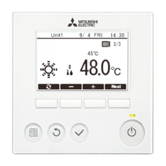
Hot Water Heat Pump & Chilling Units
Remote Controller
PAR-W31MAA
Refer to the Installation Manuals that
are provided with the connected units
(Hot Water Heat Pump & Chilling Units)
for how to connect cables and how to
install them.
To ensure safety and correct use of the
product, thoroughly read this manual
prior to installation.
Retain this manual for future reference.
For distribution to dealers and contractors
Contents
Safety Precautions ...................................................................2
1. Parts to be used ..................................................................7
1-1. Package contents .................................................................7
1-2. Commercially available parts ................................................7
2. General description of installation .......................................8
3. Selecting an installation site ................................................9
3-1. Notes to ensure optimal product functionality .......................9
4. Installation/wiring work ......................................................10
4-1. Construction work procedures and installation ...................10
4-2. Differences with previous installation methods ...................10
4-3. Installation and electrical work ............................................10
4-4. Service ................................................................................16
5. Check after installation work .............................................17
5-1. Installation work check list ..................................................17
5-2. Making the settings for the hot water sensor ......................17
5-3. Removing the protective film ...............................................17
6. Trial run .............................................................................17
6-1. Trial run procedure ..............................................................17
6-2. Items to check during the trial run .......................................17
7. Explanations to customers ................................................17
8-1. Daily maintenance ..............................................................18
periods ................................................................................18
9. Parts names ......................................................................19
9-2. Using the function buttons ..................................................20
10. Preparations ......................................................................20
11. Operations ........................................................................21
11-1. Turning the power on ........................................................21
11-3. Initial settings ....................................................................23
11-4. Service menu ....................................................................26
12. Before requesting repairs ..................................................29
12-1. Remote controller check ...................................................29
<ORIGINAL>
GB
WT08011X02
Installation Manual
Advertisement
Table of Contents

Related Manuals for Mitsubishi Electric PAR-W31MAA


Summary of Contents for Mitsubishi Electric PAR-W31MAA
-
Page 1: Table Of Contents
<ORIGINAL> WT08011X02 Hot Water Heat Pump & Chilling Units Remote Controller PAR-W31MAA Installation Manual For distribution to dealers and contractors Contents Safety Precautions ..............2 1. Parts to be used ..............7 1-1. Package contents ..............7 1-2. Commercially available parts ..........7 2. General description of installation ........8 3. -
Page 2: Safety Precautions
S a f ety Prec a u ti ons Th orou g h ly rea d th e f ollow i ng sa f ety p rec a u ti ons p ri or to i nsta lla ti on. O b serv e th ese p rec a u ti ons c a ref u lly to ensu re sa f ety . - Page 3 To red u c e th e ri sk of i nj u ry a nd elec tri c sh oc k , a v oi d c onta c t w i th sh a rp ed g es of c erta i n p a rts.
- Page 4 To red u c e th e ri sk of elec tri c sh oc k , sh orti ng , or ma lf u nc ti ons, k eep w i re p i ec es a nd sh ea th sh a v i ng s ou t of th e termi na l b loc k .
- Page 5 Ad d i ti ona l p rec a u ti ons To red u c e th e ri sk of ma lf u nc ti ons a nd d a ma g e to th e c ontroller, a v oi d i nsta lli ng th e c ontroller on a n elec tri c a lly c ond u c ti v e su rf a c e, su c h a s a n u np a i nted meta l sh eet.
- Page 6 To p rev ent c a b le b rea k a g e a nd ma lf u nc ti ons, d o not h a ng th e top c ontroller c a se h a ng b y th e c a b le.
-
Page 7: Parts To Be Used
1. Pa rts to b e u sed 1-1. Pa c k a g e c ontents The table below lists all the parts and their quantities included in the package. Parts name Q ty. Appearance Parts name Q ty. Appearance Roundhead cross slot screw M4×... -
Page 8: General Description Of Installation
2. G enera l d esc ri p ti on of i nsta lla ti on [ 1] I nsta lla ti on u si ng a d ou b le sw i tc h b ox Front cover Top case (supplied) (supplied) Double switch box... -
Page 9: Selecting An Installation Site
3. S elec ti ng a n i nsta lla ti on si te D o not i nsta ll th e c ontroller w h ere th ere i s a ri sk of lea k i ng f la mma b le g a s. I f f la mma b le g a s a c c u mu la tes a rou nd th e c ontroller, i t ma y i g ni te a nd c a u se a f i re or ex p losi on. -
Page 10: Installation/Wiring Work
4 . I nsta lla ti on/ w i ri ng w ork 4 -1. Constru c ti on w ork p roc ed u res a nd i nsta lla ti on When the installation site is ready for installation, carry out the installation work. [ 1] I nsta lla ti on u si ng a d ou b le sw i tc h b ox Before applying a wall finish material, install the double switch box, connect it to the conduit tube and route the cable beforehand. - Page 11 ( 2) S ea l th e c a b le a c c ess h ole w i th p u tty . ■ Installation using a double switch box Procedures 1. Seal the remote controller cable access hole at the connection of double switch box and conduit tube with putty.
- Page 12 To red u c e th e ri sk of elec tri c sh oc k , sh orti ng , or ma lf u nc ti ons, k eep w i re p i ec es a nd sh ea th sh a v i ng s ou t of th e termi na l b loc k .
- Page 13 To a v oi d d a ma g e to th e c ontroller, d o not ov erti g h ten th e sc rew s. To a v oi d d a ma g e to th e c ontroller, d o not ma k e h oles on th e c ontroller c ov er. ( 6 ) D ri ll a c a b le h ole.
- Page 14 ( 8) S ec u re th e c a b les i n th e c la mp s. H old th e c a b les i n p la c e w i th c la mp s to p rev ent u nd u e f orc e f rom b ei ng a p p li ed to th e termi na l b loc k a nd c a u si ng c a b le b rea k a g e.
- Page 15 [ 2] Remov i ng th e remote c ontroller f ront c ov er a nd top c a se ( 1) Remov e th e f ront c ov er. Procedures 1. Press the flat-tip screwdriver with a 4-7 mm (5/32- 9/32 in) wide blade onto one of the two mounting tabs in the bottom of the remote controller, or push the plate service tool onto both of the tabs in the...
-
Page 16: Service
( 3) Atta c h th e f ront c ov er a nd top c a se. Two mounting tabs are at the top of the top case. Wall Procedures 1. Hook the mounting tabs onto the bottom case and click the top case into place. -
Page 17: Check After Installation Work
5 . Ch ec k a f ter i nsta lla ti on w ork When you have completed the installation work, inspect the work again by referring to the table below. Be sure to correct any problems found during the inspection. (Failing to correct problems could not only impair functioning but could also pose a safety haz ard.) 5 -1. -
Page 18: For The Safe And Long-Term Use Of The Remote Controller
8. F or th e sa f e a nd long -term u se of th e remote c ontroller 8-1. D a i ly ma i ntena nc e 8-1-1. Clea ni ng th e c ov er First wipe with a soft cloth moistened with mild detergent and then wipe with a dry cloth to remove all traces of detergent. -
Page 19: Parts Names
9 . Pa rts na mes 9 -1. E x p la na ti on of ea c h b u tton on th e remote c ontroller ⑦ Backlit LCD ② Function button [ F1] , [ F2] , [ F3] , and [ F4] from the left) ⑥... -
Page 20: Using The Function Buttons
9 -2. U si ng th e f u nc ti on b u ttons < E x a mp le of u se on th e Ma i n menu sc reen> 9/ 4 14:30 Unit1 Cursor Move the cursor to the desired function with the [ F2] Schedule Power Save and [ F3] buttons, and press the [ Select] button to go to the next page. -
Page 21: Operations
11. O p era ti ons 11-1. Tu rni ng th e p ow er on Procedures Unit1 1. Turn the connected units on. Please wait When the connected units are turned on, the screen shown on the right appears. If it starts up normally, the Main display appears. -
Page 22: Unit Initial Set (Initial Settings For The Connected Units)
11-2. U ni t i ni ti a l set ( I ni ti a l setti ng s f or th e c onnec ted u ni ts) Make the initial settings for each of the connected units using “ Main menu” > “ Service” > “ Unit initial set” . Change the settings as necessary. -
Page 23: Initial Settings
11-3. I ni ti a l setti ng s From the Main display, select “ Main menu” > “ Initial settings” to make the settings for the remote controller. Initial settings menu (1/2) Initial settings menu (2/2) Unit1 If a system controller is Date/Time RC name connected, the following... - Page 24 [ 3] D a y li g h t sa v i ng ti me Procedures Unit1 Daylight saving time 1. To set daylight saving time, press the [ F1] button to enable daylight saving Start time. 2. The display format changes as shown below each time you press [ F2] . Select the item to be changed and then use the [ F3] or [ F4] button to change the setting.
- Page 25 [ 6 ] RC na me Sets the remote controller name displayed on the Main display. Unit1 Y ou can select and enter up to 10 characters for the remote controller name. Procedures Unit1 9/ 4 14:30 1. Use the [ F1] to [ F4] buttons to select a character and the [ Select] button to Unit confirm characters one at a time.
-
Page 26: Service Menu
11-4 . S erv i c e menu < Ma i ntena nc e p a ssw ord i s req u i red . > From the Main display, select “ Main menu” > “ Service” to set and use the Service menu options. Procedures Unit1 1. - Page 27 [ 2] Ch ec k E rror h i story Procedures Unit1 Check Error history 1. Select “ Check” in the Service menu and press the [ Select] button. Self check The Check menu screen appears. Remote controller check ( 1) D i sp la y i ng th e error h i story Procedures Unit1 Error history...
- Page 28 ( 2) Resetti ng th e error h i story Unit1 Procedures Self check 1. Press the [ F4] (Reset) button while the error history is displayed. M-NET address Code A confirmation screen appears. Reset current error? Y es 2. In the confirmation screen, press the [ F3] (Y es) button. Unit1 This deletes the error history for the connected unit.
-
Page 29: Before Requesting Repairs
12. B ef ore req u esti ng rep a i rs 12-1. Remote c ontroller c h ec k If the remote controller fails to work, use this function to carry out a remote controller check. Check whether the remote controller LCD is working. ( 1) N oth i ng i s d i sp la y ed on th e remote c ontroller L CD If the correct voltage (8.5-12 V DC) is not applied to the remote controller, nothing will be displayed on the remote controller LCD. - Page 30 WT08011X 02...
- Page 31 WT08011X 02...
- Page 32 H E AD O F F I CE : TOK Y O BLDG., 2-7-3, MARUNOUCHI, CHIY ODA-K U, TOK Y O 100-8310, J APAN MAN U F ACTU RE R: MITSUBISHI ELECTRIC CORPORATION Air-conditioning & Refrigeration Systems Works 5-66, Tebira 6 Chome, Wakayama-city, 640-8686, J apan...
Need help?
Do you have a question about the PAR-W31MAA and is the answer not in the manual?
Questions and answers