Table of Contents
Advertisement
Quick Links
Advertisement
Table of Contents

Related Manuals for Texas Instruments TPA6120A2EVM


Summary of Contents for Texas Instruments TPA6120A2EVM
- Page 1 TPA6120A2 Evaluation Module User’s Guide May 2004 HPA Audio Power SLOU169...
- Page 2 TI product or service and is an unfair and deceptive business practice. TI is not responsible or liable for any such statements. Following are URLs where you can obtain information on other Texas Instruments products and application solutions:...
- Page 3 EVM IMPORTANT NOTICE Texas Instruments (TI) provides the enclosed product(s) under the following conditions: This evaluation kit being sold by TI is intended for use for ENGINEERING DEVELOPMENT OR EVALUATION PURPOSES ONLY and is not considered by TI to be fit for commercial use. As such, the goods being provided may not be complete in terms of required design-, marketing-, and/or manufacturing-related protective considerations, including product safety measures typically found in the end product incorporating the goods.
- Page 4 EVM User’s Guide. When placing measurement probes near these devices during operation, please be aware that these devices may be very warm to the touch. Mailing Address: Texas Instruments Post Office Box 655303 Dallas, Texas 75265 Copyright 2004, Texas Instruments Incorporated...
- Page 5 Chapter 1 – Introduction Chapter 2 – Getting Started Chapter 3 – Customizing the EVM Chapter 4 – EVM Circuit and Layout Related Documentation From Texas Instruments SLOS431 − TPA6120A2 data sheet If you need Assistance Contact your local TI sales representative.
-
Page 7: Table Of Contents
Contents Contents Introduction ..............Description . - Page 8 Contents Figures Top Layer With Numbered Callouts 2−1 ......... . . 4−1 Top Layer of the TPA6120A2 EVM .
-
Page 9: Introduction
Chapter 1 Introduction The TPA6120A2 is a high-fidelity audio amplifier. The amplifier can operate from a split power supply, and is designed for low noise, high dynamic range performance. Topic Page Description ........... Performance Specifications . -
Page 10: Description
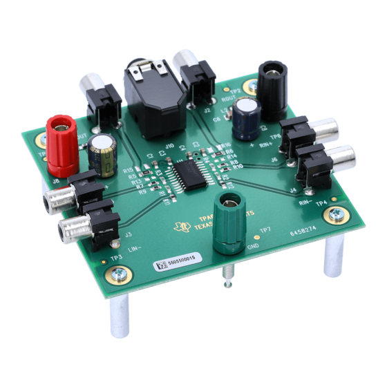
Description 1.1 Description The TPA6120A2 EVM is designed to operate specifically with a split power supply, and is configured such that both left and right channels have a noninverting gain of 2 V/V. The output signal is routed into RCA jacks J1 and J2, as well as the 1/4 inch headphone jack, J10. - Page 11 Chapter 2 Getting Started Follow these steps to use the TPA6120A2 EVM in its original configuration. No soldering is necessary. Connection to the TPA6120A2 EVM can be made with banana plugs, RCA jacks, and a 1/4 inch headphone jack. See Figure 2−1 for an illustration of the top layer.
-
Page 12: Power Supply
Power Supply 2.1 Power Supply 1) Make sure all external power supplies are turned off. 2) Connect an external power supply with the positive voltage set between 5 V and 15 V to the terminal marked +12 V (J8) on the EVM. 3) Connect the negative voltage to the terminal marked −12 V (J9), making sure the negative voltage is set to the same magnitude as that of the positive (i.e., ±5 V, ±12 V, ±15 V). -
Page 13: Top Layer With Numbered Callouts
Power Up Figure 2−1. Top Layer With Numbered Callouts (From paragraphs 2.1 through 2.3) Getting Started... - Page 14 Power Up (This page has been left blank intentionally.)
- Page 15 Chapter 3 Customizing The EVM The TPA6120A2 EVM comes in a noninverting configuration with a gain of 2 V/V. However, the EVM is designed to be flexible, and can be converted to operate in inverting and differential configurations. The TPA6120A2 EVM can also be operated in a single power supply configuration.
-
Page 16: Inverting Configuration
Inverting Configuration 3.1 Inverting Configuration The TPA6120A2 EVM can be converted to operate in an inverting gain configuration. To do this, it is necessary to remove resistors R11 and R12, then connect the audio source to RCA jacks LIN− (J3) and RIN− (J4) instead of LIN+ (J5) and RIN+ (J6). - Page 17 Chapter 4 EVM Circuit and Layout The TPA6120A2 EVM layout was carefully planned to minimize the capacitance and inductance detected by the output and input pins of the amplifier. Test points are available, but intentionally left unpopulated to keep signal interference as low as possible. This chapter includes the EVM layout, the TPA6120A2 EVM component selection, schematic, and bill of materials.
-
Page 18: Tpa6120A2 Evm Top Layer
TPA6120A2 EVM Top Layer 4.1 TPA6120A2 EVM Top Layer Figure 4−1 shows the top layer of the TPA6120A2 EVM. The RCA jacks at the inputs are configured to short to ground when no plug is inserted. The noninverting configuration of the EVM requires that RIN− and LIN− be at ground. -
Page 19: Tpa6120A2 Evm Bottom Layer
TPA6120A2 EVM Bottom Layer 4.2 TPA6120A2 EVM Bottom Layer Figure 4−2 shows the bottom layer of the TPA6120A2 EVM. Note that the copper has been removed from around the capacitive sensitive nodes. It is important to remember that the thermal pad on the underside of the IC must be properly soldered to the board at all times. -
Page 20: Component Selection
The value for R9 must be chosen carefully. The value has a direct impact on the output offset voltage and the loading of the audio source. In the configuration of the TPA6120A2EVM, where the input and feedback resistors (R1 and R3) are each 1-kΩ, a 500-Ω resistor would be the best choice for offset performance. -
Page 21: Schematic
Schematic The TPA6120A2 EVM uses 4.02-kΩ resistors to tie the positive terminals to ground. This value is a good compromise between the device’s effect on the performance of the audio source and the output offset voltage. When the source is removed or is off (or high impedance), the maximum output offset value possible with a 4.02-kΩ... -
Page 22: Bill Of Materials
Bill of Materials 4.6 Bill of Materials Table 4−1. TPA6120A2 EVM Bill of Materials Manufacturer Distributor Component Component Value Value Size Size Name Number Name Number 10 µF, 50V, +80/−20%, F C5, C6 1210 Panasonic ECJ−4YF1H106Z Digi−Key PCC2308TR−ND C1, C2, C3, 0.1 µF, 50V, ±10%, X7R 0805 Panasonic...
Need help?
Do you have a question about the TPA6120A2EVM and is the answer not in the manual?
Questions and answers