Table of Contents
Advertisement
Quick Links
This manual describes the operations of the TPA6404Q1E2EVM. The TPA6404Q1E2EVM is a stand-
alone EVM. The PurePath™ Control Console 3 GUI (PPC3) is used to initialize and operate the EVM. The
main topics of this document are:
•
Hardware implementation and descriptions
•
Software implementation and descriptions
•
TPA6404 EVM operations (hardware and software)
Required equipment and accessories:
1. TPA6404 EVM
2. USB A male to micro B male cable
3. Power Supply Unit (PSU) up to 18 V, 6-A capable
4. 1-4 resistive loads or speaker loads
5. 8 pairs of wires stripped both ends
6. 2-mm slotted screwdriver
7. Desktop or laptop PC with Microsoft
8. Access to the internet for downloading software
1
2
3
4
1
2
3
4
5
6
7
8
9
10
11
12
13
14
15
16
17
18
SLOU479A - October 2017 - Revised December 2017
Submit Documentation Feedback
Windows
®
..........................................................................................................
...........................................................................................................
.....................................................................................................
............................................................................................................
.........................................................................................................
...................................................................................................
................................................................................................................
.....................................................................................................
.............................................................................................
....................................................................................
...............................................................................................
.......................................................................................
.....................................................................................................
..................................................................................................
...........................................................................................
.................................................................................................
.............................................................................................
............................................................................................
.....................................................................................................
...............................................................................................
Copyright © 2017, Texas Instruments Incorporated
SLOU479A - October 2017 - Revised December 2017
TPA6404-Q1 Evaluation Module
7 OS
®
Contents
.......................................................................
List of Figures
......................................................................
User's Guide
TPA6404-Q1 Evaluation Module
2
4
9
16
2
3
4
5
5
6
7
8
9
10
10
11
11
12
12
13
13
14
1
Advertisement
Table of Contents

Subscribe to Our Youtube Channel
Related Manuals for Texas Instruments TPA6404-Q1


Summary of Contents for Texas Instruments TPA6404-Q1
-
Page 1: Table Of Contents
..................... AC Load Diagnostics Section .................... DC Load Diagnostics Section ..................... Register Map Window ....................I2C Window – I2C Logging SLOU479A – October 2017 – Revised December 2017 TPA6404-Q1 Evaluation Module Submit Documentation Feedback Copyright © 2017, Texas Instruments Incorporated... -
Page 2: Hardware Overview
TPA6404Q1 Device Schematic ..............TPA6404Q1 EVM Power Supply Input Schematic Trademarks PurePath is a trademark of Texas Instruments. Microsoft, Windows are registered trademarks of Microsoft Corporation. All other trademarks are the property of their respective owners. Hardware Overview TPA6404Q1 Evaluation Module Description The TPA6404Q1 EVM can operate as a stand-alone EVM. -
Page 3: Evm Block Diagram
FILTER TPA6404 Differential DC Blocking Inputs RC LPF Capacitors Copyright © 2017, Texas Instruments Incorporated Figure 2. EVM Block Diagram SLOU479A – October 2017 – Revised December 2017 TPA6404-Q1 Evaluation Module Submit Documentation Feedback Copyright © 2017, Texas Instruments Incorporated... -
Page 4: Software Overview
Once approval is given, download the software from www.ti.com/mysecuresoftware. Figure 3. PPC3 Download Window Run the installation program. Also download the PPC3 User Manual (slou408) for further instructions. TPA6404-Q1 Evaluation Module SLOU479A – October 2017 – Revised December 2017 Submit Documentation Feedback Copyright © 2017, Texas Instruments Incorporated... -
Page 5: Ppc3 Window
“sign in” to see TPA6404 EVM application. All of the Apps in Figure 5 may not be displayed for you. Figure 5. Available Apps Window SLOU479A – October 2017 – Revised December 2017 TPA6404-Q1 Evaluation Module Submit Documentation Feedback Copyright © 2017, Texas Instruments Incorporated... -
Page 6: Tpa6404 Evm Home Window
If the EVM is not powered on or the USB is not connected, only TPA6404 EVM – Offline is displayed. Figure 6. TPA6404 EVM Home Window TPA6404-Q1 Evaluation Module SLOU479A – October 2017 – Revised December 2017 Submit Documentation Feedback Copyright © 2017, Texas Instruments Incorporated... -
Page 7: Tpa6404 Evm Register Map Window
The Register Map indicates the current setting of all the registers in the TPA6404 device. Figure 7. TPA6404 EVM Register Map Window SLOU479A – October 2017 – Revised December 2017 TPA6404-Q1 Evaluation Module Submit Documentation Feedback Copyright © 2017, Texas Instruments Incorporated... -
Page 8: Tpa6404 Evm Device Monitor & Control Window
The Register Map indicates the current setting of all the registers in TPA6404. Figure 8. TPA6404 EVM Device Monitor & Control Window TPA6404-Q1 Evaluation Module SLOU479A – October 2017 – Revised December 2017 Submit Documentation Feedback Copyright © 2017, Texas Instruments Incorporated... -
Page 9: Tpa6404 Evm Start Up
On the EVM, first switch up the STANDBY switch and then the MUTE switch • The audio can now be streamed to the speakers SLOU479A – October 2017 – Revised December 2017 TPA6404-Q1 Evaluation Module Submit Documentation Feedback Copyright © 2017, Texas Instruments Incorporated... -
Page 10: Device Monitor & Control Window
Figure 11. Global Control Section The Reset button is a software reset. This puts the device back in default settings. TPA6404-Q1 Evaluation Module SLOU479A – October 2017 – Revised December 2017 Submit Documentation Feedback Copyright © 2017, Texas Instruments Incorporated... -
Page 11: Channel Control Section
14.4 VDC. The gain setting is selectable via the drop-down menu in the Gain box. SLOU479A – October 2017 – Revised December 2017 TPA6404-Q1 Evaluation Module Submit Documentation Feedback Copyright © 2017, Texas Instruments Incorporated... -
Page 12: Faults / Warnings Section
Click on the icon located on the top right of the AC load diagnostics box to see the results. TPA6404-Q1 Evaluation Module SLOU479A – October 2017 – Revised December 2017 Submit Documentation Feedback Copyright © 2017, Texas Instruments Incorporated... -
Page 13: Dc Load Diagnostics Section
Select a particular register then double click on any bit, the bit will change state. This state is executed at the end of the click. Figure 17. Register Map Window SLOU479A – October 2017 – Revised December 2017 TPA6404-Q1 Evaluation Module Submit Documentation Feedback Copyright © 2017, Texas Instruments Incorporated... -
Page 14: I2C Window - I2C Logging
The I2C commands can also be copied to the clip board by clicking the icon next to trash bin icon. Figure 19. I2C Window – Sending I2C Commands TPA6404-Q1 Evaluation Module SLOU479A – October 2017 – Revised December 2017 Submit Documentation Feedback Copyright © 2017, Texas Instruments Incorporated... - Page 15 Execute button on the bottom left corner. The I2C commands are sent to the device when the “Execute” button is pressed. SLOU479A – October 2017 – Revised December 2017 TPA6404-Q1 Evaluation Module Submit Documentation Feedback Copyright © 2017, Texas Instruments Incorporated...
-
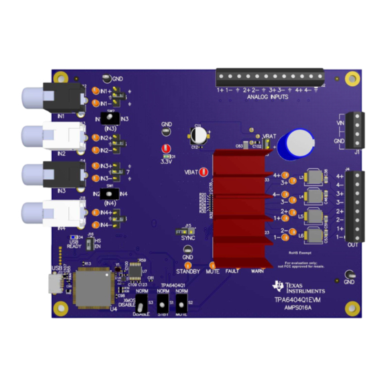
Page 16: Board Layouts, Bill Of Materials, And Schematic
Board Layouts, Bill of Materials, and Schematic TPA6404 EVM Layouts Figure 20 Figure 21 illustrate the EVM board layouts. Figure 20. TPA6404Q1 EVM Top TPA6404-Q1 Evaluation Module SLOU479A – October 2017 – Revised December 2017 Submit Documentation Feedback Copyright © 2017, Texas Instruments Incorporated... - Page 17 Board Layouts, Bill of Materials, and Schematic www.ti.com Figure 21. TPA6404Q1 EVM Bottom SLOU479A – October 2017 – Revised December 2017 TPA6404-Q1 Evaluation Module Submit Documentation Feedback Copyright © 2017, Texas Instruments Incorporated...
- Page 18 Board Layouts, Bill of Materials, and Schematic www.ti.com TPA6404E1 EVM Schematic Figure 22 Figure 23 illustrate the EVM schematics. Figure 22. TPA6404Q1 EVM Analog Inputs Schematic TPA6404-Q1 Evaluation Module SLOU479A – October 2017 – Revised December 2017 Submit Documentation Feedback Copyright © 2017, Texas Instruments Incorporated...
- Page 19 Board Layouts, Bill of Materials, and Schematic www.ti.com Figure 23. TPA6404Q1 EVM XMOS I/O Schematic SLOU479A – October 2017 – Revised December 2017 TPA6404-Q1 Evaluation Module Submit Documentation Feedback Copyright © 2017, Texas Instruments Incorporated...
- Page 20 Board Layouts, Bill of Materials, and Schematic www.ti.com Figure 24. TPA6404Q1 Device Schematic TPA6404-Q1 Evaluation Module SLOU479A – October 2017 – Revised December 2017 Submit Documentation Feedback Copyright © 2017, Texas Instruments Incorporated...
- Page 21 Board Layouts, Bill of Materials, and Schematic www.ti.com Figure 25. TPA6404Q1 EVM Power Supply Input Schematic SLOU479A – October 2017 – Revised December 2017 TPA6404-Q1 Evaluation Module Submit Documentation Feedback Copyright © 2017, Texas Instruments Incorporated...
- Page 22 Updated Miscellaneous Control Section section............• Updated TPA6404Q1 EVM Top and TPA6404Q1 EVM Bottom images....................• Changed Figure 22 through Figure Revision History SLOU479A – October 2017 – Revised December 2017 Submit Documentation Feedback Copyright © 2017, Texas Instruments Incorporated...
- Page 23 STANDARD TERMS FOR EVALUATION MODULES Delivery: TI delivers TI evaluation boards, kits, or modules, including any accompanying demonstration software, components, and/or documentation which may be provided together or separately (collectively, an “EVM” or “EVMs”) to the User (“User”) in accordance with the terms set forth herein.
- Page 24 FCC Interference Statement for Class B EVM devices NOTE: This equipment has been tested and found to comply with the limits for a Class B digital device, pursuant to part 15 of the FCC Rules. These limits are designed to provide reasonable protection against harmful interference in a residential installation.
- Page 25 【無線電波を送信する製品の開発キットをお使いになる際の注意事項】 開発キットの中には技術基準適合証明を受けて いないものがあります。 技術適合証明を受けていないもののご使用に際しては、電波法遵守のため、以下のいずれかの 措置を取っていただく必要がありますのでご注意ください。 1. 電波法施行規則第6条第1項第1号に基づく平成18年3月28日総務省告示第173号で定められた電波暗室等の試験設備でご使用 いただく。 2. 実験局の免許を取得後ご使用いただく。 3. 技術基準適合証明を取得後ご使用いただく。 なお、本製品は、上記の「ご使用にあたっての注意」を譲渡先、移転先に通知しない限り、譲渡、移転できないものとします。 上記を遵守頂けない場合は、電波法の罰則が適用される可能性があることをご留意ください。 日本テキサス・イ ンスツルメンツ株式会社 東京都新宿区西新宿6丁目24番1号 西新宿三井ビル 3.3.3 Notice for EVMs for Power Line Communication: Please see http://www.tij.co.jp/lsds/ti_ja/general/eStore/notice_02.page 電力線搬送波通信についての開発キットをお使いになる際の注意事項については、次のところをご覧ください。http:/ /www.tij.co.jp/lsds/ti_ja/general/eStore/notice_02.page 3.4 European Union 3.4.1 For EVMs subject to EU Directive 2014/30/EU (Electromagnetic Compatibility Directive): This is a class A product intended for use in environments other than domestic environments that are connected to a low-voltage power-supply network that supplies buildings used for domestic purposes.
- Page 26 Notwithstanding the foregoing, any judgment may be enforced in any United States or foreign court, and TI may seek injunctive relief in any United States or foreign court. Mailing Address: Texas Instruments, Post Office Box 655303, Dallas, Texas 75265 Copyright © 2017, Texas Instruments Incorporated...
- Page 27 IMPORTANT NOTICE FOR TI DESIGN INFORMATION AND RESOURCES Texas Instruments Incorporated (‘TI”) technical, application or other design advice, services or information, including, but not limited to, reference designs and materials relating to evaluation modules, (collectively, “TI Resources”) are intended to assist designers who are developing applications that incorporate TI products;...
Need help?
Do you have a question about the TPA6404-Q1 and is the answer not in the manual?
Questions and answers