Table of Contents
Advertisement
Quick Links
www.ti.com
User's Guide
TPA6304-Q1 Evaluation Module
Robert Clifton
This manual describes the operations of the TPA6304Q1EVM. The TPA6304Q1EVM is a stand-alone Evaluation
Module (EVM). The PurePath
2 Hardware Overview................................................................................................................................................................
2.1 TPA6304Q1 Evaluation Module Description......................................................................................................................
2.2 TPA6304-Q1 Evaluation Module Functions.......................................................................................................................
Overview..................................................................................................................................................................6
3.1 PurePath™ Console 3 (PPC3) Access and Description....................................................................................................
3.3 PurePath™ Console 3 - TPA6304Q1EVM Register Map Window....................................................................................
3.4 PurePath™ Console 3 - TPA6304Q1EVM Monitor & Control Window...........................................................................
4 TPA6304-Q1 Start Up............................................................................................................................................................
Setup....................................................................................................................................................11
4.3 TPA6304-Q1 Settings on Register Map Window.............................................................................................................
Window.........................................................................................................................................................17
Layout....................................................................................................................................................................19
5.2 Schematic........................................................................................................................................................................
Materials.................................................................................................................................................................24
History.......................................................................................................................................................................28
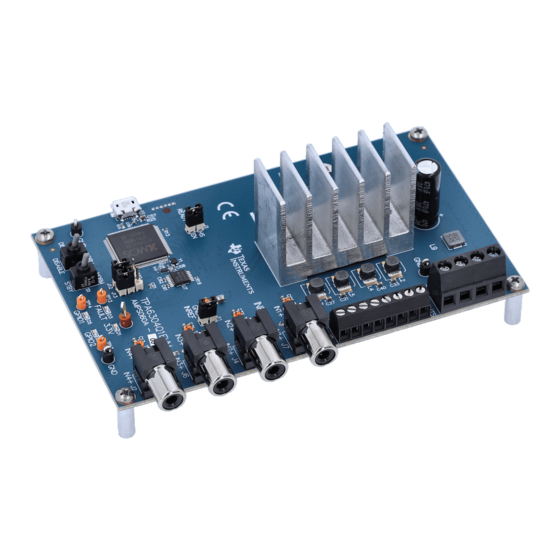
Figure 2-1. TPA6304Q1EVM.......................................................................................................................................................
Figure 2-2. EVM Block Diagram..................................................................................................................................................
Figure 3-1. PPC3 Download Window..........................................................................................................................................
Figure 3-2. PPC3 Window...........................................................................................................................................................
Figure 3-3. Available Apps Window.............................................................................................................................................
Figure 3-5. PPC3 Installed Apps.................................................................................................................................................
Figure 3-7. TPA6304Q1EVM Register Map Window...................................................................................................................
Figure 3-8. TPA6304Q1EVM Device Monitor & Control Window..............................................................................................
Figure 4-1. TPA6304Q1EVM Connections................................................................................................................................
Figure 4-3. Device State Control Section..................................................................................................................................
Figure 4-4. Master Mode/Slave Mode Section..........................................................................................................................
Figure 4-5. Channel Control Section.........................................................................................................................................
Figure 4-6. Miscellaneous Control Section................................................................................................................................
SLAU813A - SEPTEMBER 2019 - REVISED OCTOBER 2020
Submit Document Feedback
ABSTRACT
™
Control Console 3 GUI (PPC3) is used to initialize and operate the EVM.
Table of Contents
Accessories:................................................................................................................................3
Window................................................................................................8
Materials..................................................................................................................19
List of Figures
App............................................................................................................................................7
Window...............................................................................................................................8
Window...........................................................................................................................12
Section..........................................................................................................14
Section........................................................................................................................................14
Section..................................................................................................................................15
Section................................................................................................................................15
Copyright © 2020 Texas Instruments Incorporated
Window...........................................................................................12
Table of Contents
TPA6304-Q1 Evaluation Module
4
4
5
6
9
10
11
17
21
4
5
6
6
7
8
9
10
11
12
13
13
13
1
Advertisement
Table of Contents

Related Manuals for Texas Instruments TPA6304-Q1


Summary of Contents for Texas Instruments TPA6304-Q1
-
Page 1: Table Of Contents
3.3 PurePath™ Console 3 – TPA6304Q1EVM Register Map Window..................3.4 PurePath™ Console 3 – TPA6304Q1EVM Monitor & Control Window................4 TPA6304-Q1 Start Up................................4.1 TPA6304Q1EVM Setup..............................11 4.2 TPA6304-Q1 Settings on Device Monitor & Control Window...................12 4.3 TPA6304-Q1 Settings on Register Map Window......................4.4 I2C Monitor Window.................................17 5 Board Layout, Schematic and Bill of Materials........................19... - Page 2 Table 5-1. Bill of Materials................................24 Trademarks PurePath ™ is a trademark of Texas Instruments. All other trademarks are the property of their respective owners. TPA6304-Q1 Evaluation Module SLAU813A – SEPTEMBER 2019 – REVISED OCTOBER 2020 Submit Document Feedback Copyright © 2020 Texas Instruments Incorporated...
-
Page 3: Required Equipment And Accessories
4. 1-4 resistive loads or speaker loads 5. 2-6 pair of wires stripped both ends 6. 2-mm slotted screwdriver 7. 1-4 RCA cables SLAU813A – SEPTEMBER 2019 – REVISED OCTOBER 2020 TPA6304-Q1 Evaluation Module Submit Document Feedback Copyright © 2020 Texas Instruments Incorporated... -
Page 4: Hardware Overview
The TPA6304Q1EVM is a stand-alone EVM. USB adapter is provided for a more thorough evaluation of the device. Figure 2-1 shows the EVM board. Figure 2-1. TPA6304Q1EVM TPA6304-Q1 Evaluation Module SLAU813A – SEPTEMBER 2019 – REVISED OCTOBER 2020 Submit Document Feedback Copyright © 2020 Texas Instruments Incorporated... -
Page 5: Tpa6304-Q1 Evaluation Module Functions
– J5 allows VBAT to be supplied by PVDD or another power supply. – J11 ties INREF to GND. – J12 and J13 allow for external I2C controller to run I2C commands the the TPA6304-Q1. – J14, J15, and J16 allow multiple input channels to be tied to the same input source. -
Page 6: Software Overview
PPC3. Click Sign in to see TPA6304 EVM application. Figure 3-2. PPC3 Window Different Apps might be displayed in Figure 3-3 depending on the user's access. TPA6304-Q1 Evaluation Module SLAU813A – SEPTEMBER 2019 – REVISED OCTOBER 2020 Submit Document Feedback Copyright © 2020 Texas Instruments Incorporated... -
Page 7: Figure 3-3. Available Apps Window
Software Overview Figure 3-3. Available Apps Window Click the TPA6304 EVM App box to download the TPA6304-Q1 application. An Installation window appears, next click Install. Figure 3-4 shows the downloading progress of the application. Figure 3-4. PPC3 Downloading App... -
Page 8: Purepath™ Console 3 - Tpa6304Q1Evm Home Window
Connect box in the bottom left hand corner. If the EVM is not powered on or the USB is not connected, only TPA6304Q1EVM – Offline is displayed. Figure 3-6. TPA6304Q1EVM Home Window TPA6304-Q1 Evaluation Module SLAU813A – SEPTEMBER 2019 – REVISED OCTOBER 2020 Submit Document Feedback Copyright © 2020 Texas Instruments Incorporated... -
Page 9: Purepath™ Console 3 - Tpa6304Q1Evm Register Map Window
3.3 PurePath™ Console 3 – TPA6304Q1EVM Register Map Window Click on the Register Map Box in the Home Window to display the Register Map Window. The Register Map indicates the current setting of all the registers in the TPA6304-Q1 device. Figure 3-7. TPA6304Q1EVM Register Map Window SLAU813A –... -
Page 10: Purepath™ Console 3 - Tpa6304Q1Evm Monitor & Control Window
Click on Device Monitor & Control box in the Home Window to display Device Monitor & Control window. Figure 3-8. TPA6304Q1EVM Device Monitor & Control Window TPA6304-Q1 Evaluation Module SLAU813A – SEPTEMBER 2019 – REVISED OCTOBER 2020 Submit Document Feedback Copyright © 2020 Texas Instruments Incorporated... -
Page 11: Tpa6304-Q1 Start Up
TPA6304-Q1 Start Up 4 TPA6304-Q1 Start Up This section describes the TPA6304-Q1 start up procedure. Have all the equipment and accessories listed on the first page of this document available. 4.1 TPA6304Q1EVM Setup Figure 4-1. TPA6304Q1EVM Connections Hardware and software connections: •... -
Page 12: Tpa6304-Q1 Settings On Device Monitor & Control Window
The audio can now be streamed to the speakers 4.2 TPA6304-Q1 Settings on Device Monitor & Control Window Most of the register settings are done on the Device Monitor & Control window. The TPA6304-Q1 Register Map window is for reference. -
Page 13: Figure 4-4. Master Mode/Slave Mode Section
Clip Level box allows the user to set the detect threshold to go off at either 1% THD, 2% THD, 3% THD or 10% THD. 1% THD is the default value. SLAU813A – SEPTEMBER 2019 – REVISED OCTOBER 2020 TPA6304-Q1 Evaluation Module Submit Document Feedback Copyright © 2020 Texas Instruments Incorporated... -
Page 14: Figure 4-7. Fault / Warning Signal Configuration
The AC load diagnostics report speaker impedance and phase. The diagnostics can be performed with one or all four channels. TPA6304-Q1 Evaluation Module SLAU813A – SEPTEMBER 2019 – REVISED OCTOBER 2020 Submit Document Feedback Copyright © 2020 Texas Instruments Incorporated... -
Page 15: Figure 4-9. Ac Load Diagnostics Section
Each can be set to be either 0 degrees, 45 degrees, 90 degrees, SLAU813A – SEPTEMBER 2019 – REVISED OCTOBER 2020 TPA6304-Q1 Evaluation Module Submit Document Feedback Copyright © 2020 Texas Instruments Incorporated... - Page 16 Dephase Ch2 to Ch1, Dephase Ch3 to Ch1, and Dephase CH4 to Ch1 are 180 degree, 90 degree, and 270 degree, respectively. TPA6304-Q1 Evaluation Module SLAU813A – SEPTEMBER 2019 – REVISED OCTOBER 2020 Submit Document Feedback Copyright © 2020 Texas Instruments Incorporated...
-
Page 17: Tpa6304-Q1 Settings On Register Map Window
TPA6304-Q1 Start Up 4.3 TPA6304-Q1 Settings on Register Map Window Select a particular register then double click on any bit, that isn't reserved, and the bit changes state. This state is executed at the end of the click. Figure 4-12. Register Map Window 4.4 I2C Monitor Window... -
Page 18: Figure 4-14. I2C Monitor Window - I2C Logging
Execute button on the bottom left corner of the I2C Monitor window. The I2C commands are sent to the device when the Execute button is pressed. TPA6304-Q1 Evaluation Module SLAU813A – SEPTEMBER 2019 – REVISED OCTOBER 2020 Submit Document Feedback Copyright © 2020 Texas Instruments Incorporated... -
Page 19: Board Layout, Schematic And Bill Of Materials
Board Layout, Schematic and Bill of Materials 5 Board Layout, Schematic and Bill of Materials 5.1 Board Layout Figure 5-1. TPA6304Q1EVM Top SLAU813A – SEPTEMBER 2019 – REVISED OCTOBER 2020 TPA6304-Q1 Evaluation Module Submit Document Feedback Copyright © 2020 Texas Instruments Incorporated... -
Page 20: Figure 5-2. Tpa6304Q1Evm Bottom
Board Layout, Schematic and Bill of Materials www.ti.com Figure 5-2. TPA6304Q1EVM Bottom TPA6304-Q1 Evaluation Module SLAU813A – SEPTEMBER 2019 – REVISED OCTOBER 2020 Submit Document Feedback Copyright © 2020 Texas Instruments Incorporated... -
Page 21: Schematic
0.1uF 2.2uF 47.0k 470pF TPS3897ADRYR 0.1uF 0.1uF 0.1uF 0.1uF 0.1uF USB I/O JTAG CLOCK GENERATION Figure 5-3. Schematic (Page 1) SLAU813A – SEPTEMBER 2019 – REVISED OCTOBER 2020 TPA6304-Q1 Evaluation Module Submit Document Feedback Copyright © 2020 Texas Instruments Incorporated... -
Page 22: Figure 5-4. Schematic
GPIO2 GPIO2 GPIO2 Yellow 4.99k TP13 3.3V GPIO2 GPIO1 GPIO1 GPIO1 Yellow 4.99k TP14 GPIO1 Figure 5-4. Schematic (Page 2) TPA6304-Q1 Evaluation Module SLAU813A – SEPTEMBER 2019 – REVISED OCTOBER 2020 Submit Document Feedback Copyright © 2020 Texas Instruments Incorporated... -
Page 23: Figure 5-5. Schematic
100V VBAT 3.3V LM1086IT-3.3/NOPB 3.3V-VR 100uF 100nF 10uF 0.1uF 3.3V 3.3V Green 1.50k 3.3V Figure 5-5. Schematic (Page 3) spacer SLAU813A – SEPTEMBER 2019 – REVISED OCTOBER 2020 TPA6304-Q1 Evaluation Module Submit Document Feedback Copyright © 2020 Texas Instruments Incorporated... -
Page 24: Bill Of Materials
CAP, CERM, 2.2 uF, 25 V, +/- 10%, X7R, AEC-Q200 Grade 1, 0805 0805 CGA4J3X7R1E225K125AB Green LED, Green, SMD LED_0603 150060GS75000 Wurth Elektronik TPA6304-Q1 Evaluation Module SLAU813A – SEPTEMBER 2019 – REVISED OCTOBER 2020 Submit Document Feedback Copyright © 2020 Texas Instruments Incorporated... - Page 25 RES, 4.99 k, 1%, 0.05 W, 0201 0201 RC0201FR-7D4K99L Yageo America 43.2 RES, 43.2, 1%, 0.1 W, 0603 0603 RC0603FR-0743R2L Yageo SLAU813A – SEPTEMBER 2019 – REVISED OCTOBER 2020 TPA6304-Q1 Evaluation Module Submit Document Feedback Copyright © 2020 Texas Instruments Incorporated...
- Page 26 Fiducial mark. There is nothing to buy or mount. FID5, FID6 R36, R37, R38, R39, R40, RES, 3.3, 5%, 0.1 W, 0603 0603 CRCW06033R30JNEA Vishay-Dale R41, R42, R43 TPA6304-Q1 Evaluation Module SLAU813A – SEPTEMBER 2019 – REVISED OCTOBER 2020 Submit Document Feedback Copyright © 2020 Texas Instruments Incorporated...
- Page 27 Table 5-1. Bill of Materials (continued) Designator Value Description Package Reference Part Number Manufacturer Test Point, Multipurpose, Red, TH Red Multipurpose Testpoint 5010 Keystone SLAU813A – SEPTEMBER 2019 – REVISED OCTOBER 2020 TPA6304-Q1 Evaluation Module Submit Document Feedback Copyright © 2020 Texas Instruments Incorporated...
-
Page 28: Revision History
NOTE: Page numbers for previous revisions may differ from page numbers in the current version. Changes from Revision * (September 2019) to Revision A (October 2020) Page • Added Spread Spectrum Control Section......................15 TPA6304-Q1 Evaluation Module SLAU813A – SEPTEMBER 2019 – REVISED OCTOBER 2020 Submit Document Feedback Copyright © 2020 Texas Instruments Incorporated... - Page 29 STANDARD TERMS FOR EVALUATION MODULES Delivery: TI delivers TI evaluation boards, kits, or modules, including any accompanying demonstration software, components, and/or documentation which may be provided together or separately (collectively, an “EVM” or “EVMs”) to the User (“User”) in accordance with the terms set forth herein.
- Page 30 www.ti.com Regulatory Notices: 3.1 United States 3.1.1 Notice applicable to EVMs not FCC-Approved: FCC NOTICE: This kit is designed to allow product developers to evaluate electronic components, circuitry, or software associated with the kit to determine whether to incorporate such items in a finished product and software developers to write software applications for use with the end product.
- Page 31 www.ti.com Concernant les EVMs avec antennes détachables Conformément à la réglementation d'Industrie Canada, le présent émetteur radio peut fonctionner avec une antenne d'un type et d'un gain maximal (ou inférieur) approuvé pour l'émetteur par Industrie Canada. Dans le but de réduire les risques de brouillage radioélectrique à...
- Page 32 www.ti.com EVM Use Restrictions and Warnings: 4.1 EVMS ARE NOT FOR USE IN FUNCTIONAL SAFETY AND/OR SAFETY CRITICAL EVALUATIONS, INCLUDING BUT NOT LIMITED TO EVALUATIONS OF LIFE SUPPORT APPLICATIONS. 4.2 User must read and apply the user guide and other available documentation provided by TI regarding the EVM prior to handling or using the EVM, including without limitation any warning or restriction notices.
- Page 33 Notwithstanding the foregoing, any judgment may be enforced in any United States or foreign court, and TI may seek injunctive relief in any United States or foreign court. Mailing Address: Texas Instruments, Post Office Box 655303, Dallas, Texas 75265 Copyright © 2019, Texas Instruments Incorporated...
- Page 34 TI products. TI’s provision of these resources does not expand or otherwise alter TI’s applicable warranties or warranty disclaimers for TI products. Mailing Address: Texas Instruments, Post Office Box 655303, Dallas, Texas 75265 Copyright © 2020, Texas Instruments Incorporated...
Need help?
Do you have a question about the TPA6304-Q1 and is the answer not in the manual?
Questions and answers