Table of Contents
Advertisement
Quick Links
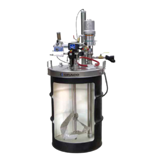
Operation and Parts
Xtreme
Xtreme - - - Duty™
Xtreme
Duty™
Duty™ Agitator
Packages
Packages
Packages
For
For
For mixing
mixing high
mixing
high- - - viscosity
high
viscosity
viscosity coatings
professional
professional
professional use
use only.
use
only.
only.
Important
Important Safety
Important
Safety Instructions
Safety
Read all warnings and instructions in this manual and in
related manuals. Save all instructions.
100 psi (7.0 bar, 0.7 MPa) Maximum
Air Input Pressure
See page 3 for model information.
Agitator and
Agitator
coatings supplied
coatings
supplied in in in 55
supplied
Instructions
Instructions
PROVEN QUALITY. LEADING TECHNOLOGY.
and
and
55 gallon
55
gallon (200
gallon
(200 liter)
(200
liter) open
liter)
3A4032D
open- - - headed
open
headed drums.
headed
drums. For
drums.
EN
For
For
Advertisement
Table of Contents

Related Manuals for Graco Xtreme-Duty 25A598


Summary of Contents for Graco Xtreme-Duty 25A598
- Page 1 Operation and Parts Xtreme Xtreme Xtreme - - - Duty™ Duty™ Duty™ Agitator Agitator and Agitator 3A4032D Packages Packages Packages For mixing mixing high mixing high- - - viscosity high viscosity viscosity coatings coatings supplied coatings supplied in in in 55 supplied 55 gallon gallon (200...
-
Page 2: Table Of Contents
Operation ............13 Xtreme-Duty Agitator Packages Pressure Relief Procedure ......13 25A599 – 25A604....... 21 Setup............13 Technical Data ..........23 Using the Elevator (included in some packages) ........14 Graco Standard Warranty ....... 24 Using the Agitator ........14 3A4032D... -
Page 3: Related Manuals
Related Manuals Related Manuals Manuals Related Related Manuals Component Manuals in English: Description Description Description Manual Manual Manual 306287 Elevators and pump supports 308118 SST feed pumps, 5:1 and 10:1 ratio 307044 CS feed pump, 5:1 ratio 308738 CS feed pump, 10:1 ratio 307043 Monark®... -
Page 4: Warnings
Warnings Warnings Warnings Warnings The following warnings are for the setup, use, grounding, maintenance, and repair of this equipment. The exclamation point symbol alerts you to a general warning and the hazard symbols refer to procedure-specific risks. When these symbols appear in the body of this manual or on warning labels, refer back to these Warnings. - Page 5 Warnings WARNING WARNING WARNING MOVING PARTS PARTS HAZARD HAZARD MOVING MOVING PARTS HAZARD Moving parts can pinch, cut or amputate fingers and other body parts. • Keep clear of moving parts. • Do not operate equipment with protective guards or covers removed. •...
- Page 6 Warnings WARNING WARNING WARNING EQUIPMENT MISUSE MISUSE HAZARD HAZARD EQUIPMENT EQUIPMENT MISUSE HAZARD Misuse can cause death or serious injury. • Do not operate the unit when fatigued or under the influence of drugs or alcohol. • Do not exceed the maximum working pressure or temperature rating of the lowest Technical Data Data in all equipment manuals.
-
Page 7: System Component Identification
System Component Identification System System System Component Component Identification Component Identification Identification Key: Key: Key: Key: Key: Key: Agitator air motor and gear reducer Drum cover elevator Xtreme-Duty agitator blade Drum cover support (for elevator) Agitator shaft and coupler Feed pump Stainless steel drum cover Pump air control Recirculation tube... -
Page 8: Installation
Installation Installation Installation Installation Grounding Grounding Grounding Typical Typical Installation Typical Installation Installation Description Ref. Ref. Ref. Description Description Air Supply Line Filter Air Supply Line Lubricator The equipment must be grounded to reduce Agitator Motor the risk of static sparking. Static sparking can cause fumes to ignite or explode. -
Page 9: Agitator
Installation Assembling and and Positioning Positioning the Assembling Assembling Positioning Without Without an Without an Elevator Elevator Elevator Agitator Agitator Agitator When included in a package without an elevator, the drum cover is provided with handles for easy lifting and positioning. For additional handles, order the Handles Kit, part 237524. -
Page 10: Attaching The Blades
Installation Attaching the the Blades Blades Attaching Attaching Blades Securing Securing Securing the the Drum Drum Cover Drum Cover Cover The drum cover must be secured to the drum 1. Slide the agitator blade assembly (B1) onto to ensure proper clearance of rotating parts the shaft (C1), positioned so that the blade and prevent vibration. -
Page 11: Air Connections
Installation Air Connections Connections Connections Connect an electrically conductive 1/2 in. ID (minimum) air hose to supply air to the system air controls. Packages without an elevator will not have an elevator control, and packages without a feed pump will have the connection for the pump air hose plugged. Install an air filter upstream of the system to remove harmful dirt and moisture from the air supply. -
Page 12: Fluid Accessories
Installation Fluid Accessories Accessories Fluid Fluid Accessories The drum cover also has two 1 in. npt ports (which have 1–1/2 in. npt male threads underneath the cover) which can be used for If using a feed pump, insert the pump into one installing refill lines or suction tubes. -
Page 13: Operation
Operation Operation Operation Operation Pressure Pressure Pressure Relief Relief Procedure Relief Procedure Procedure Setup Setup Setup Follow the Pressure Relief Procedure whenever you see this symbol. To reduce the risk of serious injury from moving parts and splashing fluid, always shut off the agitator before you raise, check, or repair the agitator. -
Page 14: Using The Elevator (Included In Some Packages)
Operation Using the the Elevator Elevator Using Using Elevator NOTICE NOTICE NOTICE (included in in in some some packages) packages) (included (included some packages) To prevent air motor failure and possible damage to equipment, always keep the air Refer to the Elevators and Pump Supports motor properly lubricated. -
Page 15: Maintenance
Maintenance Maintenance Maintenance Maintenance Agitator Blades Blades Agitator Agitator Blades Materials can become electrostatically charged when stirred or blended. Dried material Moving parts, such as the impeller blade, can could allow static buildup and interfere with cut or amputate fingers. To reduce the risk grounding. -
Page 16: Service
(S), drain the oil, and thoroughly flush the housing with light flushing oil. Do not use kerosene or other flammable Refill with Graco oil (part 202659) to the proper solvents to flush the air motor. Flushing level. with flammable solvents could cause fire... -
Page 17: Parts
Parts Parts Parts Parts Xtreme Xtreme Xtreme - - - Duty Duty Agitator Duty Agitator Agitator 25A598 25A598 25A598 Ref. Part Part Part Description Description Description Qty. Qty. Qty. Ref. Part Part Part Description Description Description Qty. Qty. Qty. Ref. Ref. -
Page 18: Xtreme-Duty Agitator 25N588
Parts Xtreme Xtreme Xtreme - - - Duty Duty Agitator Duty Agitator 25N588 Agitator 25N588 25N588 Part Part Part Description Description Description Qty. Part Part Part Description Description Description Qty. Ref. Ref. Ref. Qty. Qty. Ref. Ref. Ref. Qty. Qty. - - - - - AGITATOR, drive train 01†... -
Page 19: Xtreme-Duty Agitator Drive Train
Parts Xtreme - - - Duty Duty Agitator Agitator Drive Drive Train Train Xtreme Xtreme Duty Agitator Drive Train FIRE AND EXPLOSION HAZARD Solvent and paint fumes can ignite or explode. Material can become electr ostatically char ged. Use equipment only in well ventilated ar Eliminate all ignition sour ces. - Page 20 Parts Part Part Part Description Description Description Qty. Qty. Qty. Part Part Part Description Description Description Qty. Qty. Qty. Ref. Ref. Ref. Ref. Ref. Ref. SHAFT, agitator, upper 16P919 181849 COLLAR 16U219 HOUSING, agitator 101118 SCREW 122772 SEAL, PTFE 111310 MOTOR, air, rotary 15Y360 SPACER, shaft, agitator...
-
Page 21: 25A599 - 25A604
Parts Xtreme - - - Duty Duty Agitator Agitator Packages Packages 25A599 25A599 – – – 25A604 25A604 Xtreme Xtreme Duty Agitator Packages 25A599 25A604 Agitator Packages Packages Agitator Agitator Packages Ref. Part Part Part Description Description Description Qty. Qty. Qty. - Page 22 Parts Agitator Agitator Agitator Packages Packages Packages Part Description Qty. Ref. Ref. Ref. Part Part Description Description Qty. Qty. 25A599 25A599 25A600 25A599 25A600 25A600 25A601 25A601 25A601 25A602 25A602 25A602 25A603 25A603 25A603 25A604 25A604 25A604 218956 PUMP, Monark, 5:1 cs 224350 PUMP, Monark, 5:1 sst 239326...
-
Page 23: Technical Data
Technical Data Technical Data Data Technical Technical Data Xtreme Xtreme- - - Duty Xtreme Duty Agitator Duty Agitator Agitator Models Models Models Metric U.S. U.S. U.S. Metric Metric Maximum Air Inlet Pressure 100 psi 0.7 MPa, 7 bar Gear Reducer Ratio 20:1 shaft speed is 1/20 air motor speed 60 rpm Maximum Recommended Shaft Speed... -
Page 24: Graco Standard Warranty
With the exception of any special, extended, or limited warranty published by Graco, Graco will, for a period of twelve months from the date of sale, repair or replace any part of the equipment determined by Graco to be defective. This warranty applies only when the equipment is installed, operated and maintained in accordance with Graco’s written recommendations.
Need help?
Do you have a question about the Xtreme-Duty 25A598 and is the answer not in the manual?
Questions and answers