Table of Contents
Advertisement
Quick Links
User'
User' s s s s s
User'
User'
User'
Manual
Manual
Manual
Manual
Manual
VIA
VIA
KT400A
KT400A
VIA KT400A
VIA
VIA
KT400A
KT400A mainboard
for AMD Socket A processor
for AMD Socket A processor
for AMD Socket A processor
for AMD Socket A processor
for AMD Socket A processor
TRADEMARK
All products and company names are trademarks or registered
trademarks of their respective holders.
These specifications are subject to change without notice.
mainboard
mainboard
mainboard
mainboard
Manual Revision 1.1
October 09, 2003
Advertisement
Table of Contents

Related Manuals for VIA Technologies KT400A


Summary of Contents for VIA Technologies KT400A
- Page 1 Manual Manual Manual Manual Manual KT400A KT400A mainboard mainboard VIA KT400A KT400A KT400A mainboard mainboard mainboard for AMD Socket A processor for AMD Socket A processor for AMD Socket A processor for AMD Socket A processor for AMD Socket A processor...
- Page 2 DISCLAIMER OF WARRANTIES: THERE ARE NO WARRANTIES WHICH EXTEND BEYOND THE DESCRIPTION ON THE FACE OF THE MANUFACTURER LIMITED WARRANTY. THE MANUFACTURER EXPRESSLY EXCLUDES ALL OTHER WARRANTIES, EXPRESS OR IMPLIED, REGARDING ITS PRODUCTS; INCLUDING ANY IMPLIED WARRANTIES OF MERCHANTABILITY, FITNESS FOR A PARTICULAR PURPOSE OR NONINFRINGEMENT.
-
Page 3: Table Of Contents
Table of Contents Page Section 1 Introduction Package Contents ..........1-1 Overview Athlon Processors ..........1- 2 Accelerated Graphics Port ........1- 3 Ultra ATA66/100/133 ..........1- 3 Hardware Monitoring ........... 1- 3 LAN (Optional) ............. 1- 3 Serial ATA ............1- 3 Mainboard Form-Factor ........ - Page 4 Section 4 BIOS Setup Main Menu ............4-1 Standard CMOS Setup ......... 4-2 Advanced BIOS Features ........4-3 Advanced Chipset Features ........ 4-7 Integrated Peripherals .......... 4-12 Power Management Setup ........4-17 PNP/PCI Configuration Setup ......4-21 PC Health Status ..........4-23 Power BIOS Features ..........
-
Page 5: Introduction
Introduction Section 1 INTRODUCTION Package Contents Contents Optional Items A. Mainboard G. Game port cable B. User’s manual H. S-ATA data and power cables C. Floppy drive cable I. Extra USB2.0 port cable D. HDD ribbon cable J. S/PDIF Module E. -
Page 6: Athlon Tm Processors
Introduction Athlon Processors The AMD Athlon is a seventh-generation micro architecture with an integrated L2 cache, which is powerful enough to support the bandwidth requirements of a large range of applications, hardware, graphics, and memory technologies. These processors implement advanced design techniques such as: Socket A (PGA 462) 200/266/333MHz system interface based on the Alpha™... -
Page 7: Accelerated Graphics Port
Introduction Accelerated Graphics Port (AGP) The AGP slot on the board is compliant with the new AGP 3.0 specification. This new specification enhances the functionality of the original AGP specification by allowing 8X data transfers ( 8 data samples per clock) resulting in maximum band- width of 2.1GB/s. -
Page 8: Mainboard Form-Factor
Introduction Mainboard Form-Factor This board is designed with ATX form factor - the latest industry standard for chassis design. The ATX form factor is essentially a Baby-AT baseboard rotated 90 degrees within the chassis enclosure and a new mounting configuration for the power supply. -
Page 9: I/O Shield Connector
Introduction I/O Shield Connector The board is equipped with an I/O back panel (Figure 3). Ensure that your computer case has the appropriate I/O cutout. RJ-45 LAN Parallel Port (Optional) Line-in/Rear out (Light blue) PS/2 Line-out/Front out (Lime) Mouse PS/2 Mic-in/Center&Subwoofer (Pink) Keyboard COM1... -
Page 10: System Block Diagram
Introduction System Block Diagram Figure 5: System Block Diagram Page 1-6... -
Page 11: Features
.A=JKHAI Section 2 FEATURES Mainboard Features Processor Chipset Main Memory BIOS Onboard PCI Devices Page 2-1... - Page 12 .A=JKHAI Legacy IO Controller Audio Peripheral Interfaces Page 2-2...
- Page 13 .A=JKHAI Front Panel Controller Expansion Slots Other Features Form Factor Page 2-3...
- Page 14 .A=JKHAI Page Left Blank Page 2-4...
-
Page 15: Installation
Installation Section 3 INSTALLATION Page 3-1... -
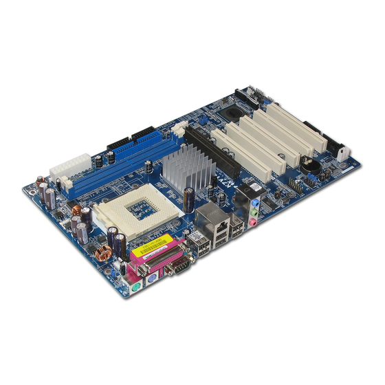
Page 16: Mainboard Layout
Installation Mainboard Layout Figure 1 Page 3-2... -
Page 17: Easy Installation Procedure
Installation Easy Installation Procedure The following must be completed before powering on your new system: 3-1. CPU Installation 3-2. Jumper Settings 3-3. System Memory Configuration 3-4. Expansion Slots 3-5. Device Connectors 3-1 CPU Installation CPU Insertion: (use AMD Athlon as reference) Step 1 Open the socket by raising the actuation lever. - Page 18 Installation Step 3 Close the socket by lowering and locking the actuation lever. Figure 4 Step 4 Thermal compound and qualified heatsink recommended by AMD are a must to avoid CPU overheat damage. For more information about installing your CPU, please refer to the AMD website article “Socket A AMD processor and Heatsink Installation Guide”...
-
Page 19: Jumper Settings
Installation 3-2 Jumper Settings JCMOS: Clear CMOS data Jumper If the CMOS data becomes corrupted or you forgot the supervisor or user password, clear the CMOS data to reconfigure the system back to the default values stored in the ROM BIOS. Settings: 1-2: Normal (Default) 2-3: Clear CMOS... -
Page 20: System Memory Configuration
Installation 3-3 System Memory Configuration Memory Layout The mainboard accommodates three PC2100/PC2700/PC3200 184-pin DIMMs (Dual In-line Memory Modules): • Supports up to 3.0GB of 266/333MHz DDR SDRAM • Supports up to 2.0GB of 400MHz DDR SDRAM (see note below) • Supports unbuffered and non-ECC DIMMs •... - Page 21 Installation DIMM Module Installation Figure 7 displays the notch on the DDR DIMM memory module. DIMMs have 184 pins and one notch that matches with the DDR DIMM socket. DIMM modules are installed by placing the chip firmly into the socket and pressing straight down as shown in figure 8 until the white clips close and the module fits tightly into the DIMM socket (figure 9).
-
Page 22: Expansion Slots
Installation 3-4 Expansion Slots AGP Slot The mainboard is equipped with an AGP slot. Make sure you install a card that supports the 1.5V specification. PCI Slots The mainboard is equipped with 5 PCI AGP Slot slots. PCI Slots Installing an Expansion Card The steps below assume that the mainboard is already installed in the system chassis. - Page 23 Installation AGP Card Installation Caution 1. AGP card component is blocked by DIMM socket lock. 2. AGP slot clicker is not locked. 3. AGP card edge connector is not inserted properly. 1. AGP card component is not blocked by DIMM socket lock. 2.
-
Page 24: Device Connectors
Installation 3-5 Device Connectors RJ-45 LAN Parallel Port (Optional) Line-in/Rear out (Light blue) PS/2 Line-out/Front out (Lime) Mouse PS/2 Mic-in/Center&Subwoofer (Pink) Keyboard COM1 COM2 USB2.0 USB2.0 ports ports Figure 10 - I/O Ports JCPU_FAN / JPWR_FAN / JSYS_FAN: CPU/Chassis Fan Power Connectors JCPU_FAN: The CPU must be kept cool by using a JCPU_FAN heatsink with fan assembly. - Page 25 Installation Floppy drive Connector FDD1 This mainboard is equipped with a floppy disk drive connector for connecting up to 2 floppy disk drives. IDE1 IDE2 IDE1/IDE2:Ultra DMA-66/100/133 Primary/Secondary IDE Connector This mainboard is equipped with 2 IDE disk connec- tors for connecting up to 4 ATA-133 IDE drives. It supports PIO and DMA mode operations for maximum data transfer rate of 133MB/sec per channel.
- Page 26 Installation CFPA: Front Panel Audio Connector When the jumpers are removed this connec- tor can be used for front panel audio. The front panel line-out phone jack should have a “normal close” switch . Without a phone- plug inserted, the rear panel audio is enabled.
- Page 27 Installation GAME1: Game/MIDI connector This port works well with any application that is compatible with the standard PC joystick. SATA1 / SATA2: Serial ATA Connectors These connectors enable you to connect two Serial ATA devices that conform to the Serial ATA specification.
- Page 28 Installation CUSB3/CUSB4: Four USB 2.0 ports This mainboard includes additional onboard USB ports, identified by two 10-pin connector. If you wish to use the additional USB ports, install the card-edge bracket to the system chassis then insert its cables to this 10-pin connector. USB2.0 allows data transfer speed up to 480Mbps.
- Page 29 Installation CFP: Front Panel Connector HD_LED This LED will light up whenever the hard drive is being accessed. PWR_LED This connects to the power button of the system chassis This switch allows you to reboot without having to power off the system thus prolonging the life of the power supply or system.
-
Page 30: Str (Suspend To Ram) Function
Installation 3-6 STR (Suspend To RAM) Function This mainboard supports the STR (Suspend To RAM) power management scheme by maintaining the appropriate power states in the DDR SDRAM interface signals. The power source to the DDR SDRAM is kept active during STR (ACPI S3). -
Page 31: Cpu Overheating Protection
Installation 3-7 CPU Overheating Protection This mainboard is equipped with CPU Overheating Protection. It will automati- cally remove power to shutdown the system when CPU temperature reaches approximately 110°C. This is to prevent long term damage to the CPU from overheating. - Page 32 Installation Page Left Blank Page 3-18...
-
Page 33: Bios Setup
BIOS Section 4 BIOS SETUP Main Menu The ROM BIOS contains a built-in Setup program which allows user to modify the basic system configuration and hardware parameters. The modified data is stored in a battery-backed CMOS, so that data will be retained even when the power is turned off. -
Page 34: Standard Cmos Setup
BIOS The main menu displays all the major selection items. Select the item you need to reconfigure. The selection is made by moving the cursor (press any direction (arrow key ) to the item and pressing the ‘Enter’ key. An on-line help message is displayed at the bottom of the screen as the cursor is moved to various items which provides a better understanding of each function. -
Page 35: Advanced Bios Features
BIOS Notes: • If the hard disk Primary Master/Slave and Secondary Master/Slave are set to Auto, the hard disk size and model will be auto-detected. • The “Halt On:” field is used to determine when the BIOS will halt the system if an error occurs. - Page 36 BIOS Hard Disk Boot Priority This item allows you to select the hard disk boot priority. Virus Warning During and after system boot up, any attempt to write to the boot sector or partition table of the hard disk drive halts the system and an error message appears. You should then run an anti-virus program to locate the virus.
- Page 37 BIOS Quick Power On Self Test This category speeds up the Power On Self Test (POST). The default is Enabled. Enabled: This setting will shorten or skip of the items checked during POST. Disabled: Normal POST. First /Second/Third/Other Boot Device The BIOS attempts to load the operating system from the devices in the sequence selected in these items.
- Page 38 BIOS APIC Mode This item allows you to enable APIC (Advanced Programmable Interrupt Controller) functionality. APIC is a chip that provides symmetric multiprocessing (SMP) for its Pentium systems. The default is Disabled. Options: Enabled, Disabled. Video BIOS Shadow This option allows video BIOS to be copied into RAM. Video Shadowing will increase the video performance of your system.
-
Page 39: Advanced Chipset Features
BIOS 4-3 Advanced Chipset Features Choose the “ADVANCED CHIPSET FEATURES” option in the CMOS SETUP UTILITY menu to display following menu. Figure 4: Chipset Features Setup System BIOS Cacheable This item allows the system to be cached in memory for faster execution. The default is Enabled. - Page 40 BIOS DRAM Clock / Drive Control Scroll to DRAM Clock/Drive Control and press <Enter>. The following screen appears: DRAM Timing For setting DRAM Timing select By SPD to follow SDRAM Serial Presence Detect Specification. Options: Manual, Auto by SPD, Turbo, Ultra. DRAM CAS Latency Enables you to select the CAS latency time.
- Page 41 BIOS Active to CMD (Trcd) This item sets the timing parameters for the system memory such as the CAS (Column Address Strobe) and RAS (Row Address Strobe). The default is by DRAM SPD. Options: 3T, 2T, 4T, 5T. DRAM Burst Length This item sets the DRAM Burst Length.
- Page 42 BIOS AGP Driving Control This item allows you to adjust the AGP driving force. Choose “Manual” to key in a AGP Driving Value in the next selection. This field is recommended to set in “Auto” to avoid any error in your system. Options: Auto, Manual.
- Page 43 BIOS CPU & PCI Bus Control Scroll to CPU & PCI Bus Control and press <Enter>. The following screen appears: PCI1/2 Master 0 WS Write When Enabled, Writes to the PCI bus are commanded with zero wait states. Options: Enabled, Disabled. PCI1/2 Post Write Enables CPU to PCI bus POST write.
-
Page 44: Integrated Peripherals
BIOS 4-4 Integrated Peripherals Figure 5: Integrated Peripherals Init Display First If two video cards are used (1 AGP and 1 PCI) this specifies which one will be the primary display adapter. The default is PCI Slot. Options: PCI Slot, AGP. VIA SATA IDE RAID Enables the onboard Serial ATA feature. - Page 45 BIOS VIA OnChip IDE Device Scroll to VIA Onchip IDE Device and press <Enter>. The following screen appears: IDE DMA transfer access Automatic data transfer between system memory and IDE device with minimum CPU intervention. This improves data throughput and frees CPU to perform other tasks. Options: Enabled, Disabled.
- Page 46 BIOS IDE HDD Block Mode Block mode is also called block transfer, multiple commands, or multiple sector read/ write. If your IDE hard drive supports block mode (most new drives do), select Enabled for automatic detection of the optimal number of block read/writes per sector the drive can support.
- Page 47 BIOS USB Keyboard Support Enable/disable support for USB keyboard under DOS. Options: Enabled, Disabled. USB Mouse Support Enable/disable support for USB mouse under DOS. Options: Enabled, Disabled. Super IO Chip Setup Scroll to Super IO Chip Setup and press <Enter>. The following screen appears: Onboard FDC Controller Select “Enabled”...
- Page 48 BIOS Parallel Port Mode This field allows the user to select the parallel port mode. Options: SPP, EPP, ECP, ECP+EPP, Normal. EPP Mode Select This field allows the user to select the EPP mode for parallel port mode. Options: EPP1.9, EPP1.7. ECP Mode USE DMA This field allows the user to select DMA1 or DMA3 for the ECP mode.
-
Page 49: Power Management Setup
BIOS 4-5 Power Management Setup Choose the “POWER MANAGEMENT SETUP” in the CMOS SETUP UTILITY to display the following screen. This menu allows the user to modify the power management parameters and IRQ signals. In general, these parameters should not be changed unless it’s absolutely necessary. - Page 50 BIOS Suspend Mode Automatically, shuts off all devices except the CPU after a preset period of system inactivity. Options: Enabled, 1 , 2, 4 ,6, 8, 10, 20, 30, 40 min and 1 hour . Video Off Option When enabled, this feature allows the VGA adapter to operate in a power saving mode. Always On: Monitor will remain on during power saving modes.
- Page 51 BIOS AC Loss Auto Restart Configures the system to auto-restart or remain off after a power interrupt. Off: System remains off after a power interrupt. On: System always restarts after a power interrupt. Auto: Depends on whether the system was safely shutdown before power failure. IRQ/Event Activity Detect Scroll to IRQ/Event Activity Detect and press <Enter>.
- Page 52 BIOS PowerOn by PCI Card An input signal from PME on the PCI card awakens the system from soft-off state. Options: Enabled, Disabled. Modem Ring Resume When set to “Enabled”, any event occurring to the Modem Ring will awaken the system from suspend state.
-
Page 53: Pnp/Pci Configuration Setup
BIOS 4-6 PNP/PCI Configuration This page lets the user to modify the PCI/ISA IRQ signals when various PCI cards are inserted. WARNING: Conflicting IRQ’s may cause the system to not find certain devices. Figure 7: PNP/PCI Configuration Setup PNP OS Installed Select “Yes”... - Page 54 BIOS PCI/VGA Palette Snoop This item is designed to overcome problems that may be caused by some nonstandard VGA cards. Options: Enabled, Disabled. Assign IRQ For VGA This item requests BIOS to assign an IRQ for the VGA. Selecting “Disabled” will free the IRQ for use by other devices.
-
Page 55: Pc Health Status
BIOS 4-7 PC Health Status Figure 8: PC Health Status Show PC Health in POST When this function is enabled the PC Health information is displayed during the POST (Power On Self Test). Options: Disabled, Enabled. CPU Warning Temperature Sets the temperature at which the computer will respond to an overheating CPU. Options: Disabled, 50 C/122 F ~ 70... - Page 56 BIOS VDIMM The voltage level of the DRAM. VBAT(V) The voltage level of the battery. + 5V, +12V, Vio, 5VSB(V) The voltage level of the switching power supply. Shutdown Temperature This is the temperature that the computer will turn off the power to combat the effects of an overheating system.
-
Page 57: Power Bios Features
BIOS 4-8 Power BIOS Features This page lets you adjust various parameters to obtain improved performance for overclocking. Warning: Overclocking requires expert knowledge and risks permanent damage to system components. We recommend you leave these parameters at their default values for proper operation. Figure 9: Frequency/Voltage Control System Performance This item will help you to configure your system. - Page 58 BIOS Setup the timing at each cycle. Options: 1T Command, 2T Command. Current FSB Frequency Display the current CPU front side bus frequency information. Current DRAM Frequency Display the current DRAM frequency information. DRAM Clock This item allows you to select DRAM clock. Options: By SPD, 100MHz, 133MHz, 166MHz, 200MHz.
-
Page 59: Defaults Menu
BIOS CPU Ratio This item allows you to select the CPU ratio. Options: Auto, x6 ~ x13. CPU Vcore Voltage This item allows you to set the CPU Vcore voltage. Options: Default, 1.400V to 1.850V in 0.025V increment and 1.850V to 2.000V in 0.050V increment. -
Page 60: Supervisor/User Password Setting
BIOS 4-10 Supervisor/User Password Setting This function lets you set either Supervisor or User Password, or both, to prevent unauthorized changes to BIOS menus. supervisor password: full rights to enter and change options of the setup menus. user password: only enter but no rights to change options of the setup menus. - Page 61 BIOS 4-11 Exiting BIOS Save & Exit Setup Pressing <Enter> on this item asks for confirmation: Save to CMOS and EXIT (Y/N)? Y Pressing “Y” stores the selections made in the menus in CMOS – a special section of memory that stays on after you turn your system off. The next time you boot your computer, the BIOS configures your system according to the Setup selections stored in CMOS.
- Page 62 BIOS Page Left Blank Page 4-30...
-
Page 63: S-Ata Raid Configuration
S-ATA RAID Configuration Section 5 S-ATA RAID CONFIGURATION Introduction This section gives a brief introduction on the RAID-related background knowledge and a brief introduction on VIA SATA RAID Host Controller. For more detailed information, please refer to user’s manual in the attached CD. RAID Basics RAID (Redundant Array of Independent Disks) is a method of combining two hard disk drives into one logical unit. - Page 64 S-ATA RAID Configuration RAID 0 (Striping) RAID 0 reads and writes sectors of data interleaved between multiple drives. If any disk member fails, it affects the entire array. The disk array data capacity is equal to the number of drive members times the capacity of the smallest member. The striping block size can be set from 4KB to 64KB.
- Page 65 S-ATA RAID Configuration K K K K K e e e e e y F y Fea eatur tures The VIA SATA RAID solution uses the VT8237 chip as a RAID controller, which is a 2-channel SATA and 1-channel ATA133 solution. The RAID software is a Windows-based software utility with graphical user interface that provides an easy- operating tool to configure and manage disk drives or disk arrays connected to the VT8237 controller.
-
Page 66: Bios Configuration Utility
S-ATA RAID Configuration BIOS Configuration Utility BIOS Configuration Utility BIOS Configuration Utility BIOS Configuration Utility BIOS Configuration Utility BIOS Configuration Utility When the system powers on, wait for the following screen to appear and press ‘Tab’ key to enter BIOS configuration utility. The main interface of BIOS configuration utility is as below: Page 5-4... - Page 67 S-ATA RAID Configuration Create Disk Array 1. Use the arrow keys to navigate the main menu. Use the up and down arrow keys to select the Create Array command and press <Enter> to call out the list of creation steps. 2.
- Page 68 S-ATA RAID Configuration 3. After array mode is selected, there are two methods to create a disk array. One method is “Auto Setup” and the other one is “Select Disk Drives”. Auto Setup allows BIOS to select the disk drives and create arrays automatically, but it does not duplicate the mirroring drives even if the user selected Create and duplicate for RAID 1 .
- Page 69 S-ATA RAID Configuration 5. Use the arrow key to highlight Start Create Process and press <Enter>. A warning message will appear, Press Y to finish the creation, or press N to cancel the creation. 6. Important note: All existing content in the hard drive will be destroyed after array creation.
- Page 70 S-ATA RAID Configuration View Serial Number of Hard Drive Highlight Serial Number View and press <Enter>. Use arrow key to select a drive, the selected drive’s serial number can be viewed in the last column. The serial number is assigned by the disk drive manufacturer. View Array Status Press the F1 key to show the array status on the lower screen.
- Page 71 S-ATA RAID Configuration Rebuild Broken RAID 1 Array When booting up the system, BIOS will detect if any member disk drives of RAID has failed or is absent. If BIOS detects any disk drive failures or missing disk drives, the status of the array will be marked as broken. If BIOS detects a broken RAID 1 array but there is a spare hard drive available for rebuilding the broken array, the spare hard drive will automatically become the mirroring drive.
- Page 72 S-ATA RAID Configuration 3. Choose Replacement Drive and Rebuild: This item enables users to select an already-connected hard drive to rebuild the broken array. After choosing a hard drive, the channel column will be activated. Highlight the target hard drive and press <Enter>, a warning message will appear.
-
Page 73: Driver Installation
Drivers Installation Section 6 Driver Installation Easy Driver Installation VIA KT400/KT400A/KT600 SERIES VIA SERVICE PACK 4IN1 DRIVER AC’97 AUDIO DRIVER (Optional) VIA 6103 LAN DRIVER USB 2.0 DRIVER VIA SATA RAID DRIVER Insert the bundled CD-disk, the main menu screen will appear. The main menu displays buttons that link you to the supported drivers, utilities and software. -
Page 74: Realtek Sound Manager Quick User-Guide
Drivers Installation Realtek Sound Manager Quick User-guide Introduction To obtain the best performance from your audio system, run the "Sound Manager" utility to adjust the settings to suit your needs. This section of the manual is intended to provide a quick user-guide to setup "Sound Manager". For more detailed information, refer to "Sound Manager manual"... - Page 75 Drivers Installation Equalizer: <Figure 3> 3. There are 10 bands of equalizer control, check "ON" when you want to adjust the equalizer. Speaker Configuration: <Figure 4> 4. This page displays the mainboards's phone jack function when a corresponding audio mode (no. of speaker) is selected. Figure 4 above shows the phone jack setup for 2 channel mode.
- Page 76 Drivers Installation Speaker Configuration: <Figure 5> 5. For 6 channel mode, the audio combination is shown above. Speaker Test: <Figure 6> 6. To test the speaker , select the “Speaker Test” page and click directly on the speakers shown on the screen. Page 6-4...
- Page 77 Drivers Installation SPDIF-In: <Figure 7> 7. This page shows S/PDIF IN function on your system. a. Click "Auto Lock" to detect S/PDIF input and display its information. b. Check "Real-time S/PDIF-In monitor" to listen to the S/PDIF IN signal through Line-out connector. SPDIF-Out: <Figure 8>...
- Page 78 Drivers Installation This board is equipped with Jack Sensing capability. If an audio device is plugged into the wrong connector, a warning message will appear to remind users to check the connection. Connector Sensing: <Figure 9> 9. Push "Start" button to start the sensing. Please remember to terminate all audio applications before starting the sensing.
- Page 79 Drivers Installation Connector Sensing: <Figure 11> 11. After closing EZ-Connector, this page will show the latest connector status as above. General: <Figure 12> 12. This page displays information regarding the audio hardware and software. To remove "Sound Manager" icon from Windows Task bar, uncheck "Show icon in system tray".
- Page 80 Drivers Installation Page Left Blank Page 6-8...
-
Page 81: Appendix
Appendix Appendix A A-1 Realtek Media Player User’s Guide Realtek Media Player Platform 06 - Reo Speedwagon 06-Reo Speedwagon - K 03:31 Functional Descriptions A. Playback Windows Display Playback windows displays the following mode information: 1. Playback Time Display 2. Voice Cancellation Mode Display 3. - Page 82 Appendix B. Playback Function Controls There are 8 selectable functions for the playback: 1. Volume control High/Low Adjustment Bar. 2. Pitch control 4-step High/Low Adjustment Bar. 3. Repeat mode Choice of Repeat, All Repeat, Random or No Repeat Mode. 4. Mute Mute On/Off Mode select.
- Page 83 Appendix D. Seeking bar Display Animated Playback Status E. Title/Play List Windows Display Currently Selected Title(s) F. Title/Play List Edit Controls There title/play list controls include “Add”, “Del”, “Clear”, “Load”, & “Store”. 1. Add Add to the Title/Play List. 2. Del Remove form the Title/Play List.
- Page 84 Appendix J. Platform Display Panel Controls The platform display panel control include “Minimize” & “Close”. 1. Minimize Minimize Platform Display Panel. 2. Close Close/Exit Platform Display Panel. K. Equalizer Control Panel The Equalizer Control Panel include “On/Off” & “Preset”. 1. On/Off Enable/Disable Equalizer.
-
Page 85: Update Your System Bios
Appendix Appendix B B-1 Update Your System BIOS Download the xxxxx.EXE file corresponding to your model from our website to an empty directory on your hard disk or floppy. Run the downloaded xxxxx.EXE file and it will self extract. Copy these extracted files to a bootable DOS floppy disk. Note: The DOS floppy disk should contain NO device drivers or other programs. - Page 86 Appendix 5. Key in File Name to save previous BIOS to file. XXXX XXXXX xxxxx.bin xxxxx.bin 6. To confirm and proceed, please key in [Y] to start the programming. XXXX XXXXX xxxxx.bin xxxxx.bin 7. The BIOS update is finished. XXXX XXXXX xxxxx.bin F10 : Exit...
-
Page 87: Eeprom Bios Remover
Appendix Appendix C C-1 EEPROM BIOS Remover Do not remove the BIOS chip, unless instructed by a technician and only with a PLCC IC extractor tool. The BIOS socket is fragile may be damaged if an improper method to replace the BIOS chip is applied. - Page 88 Appendix Page Left Blank...
Need help?
Do you have a question about the KT400A and is the answer not in the manual?
Questions and answers