Table of Contents
Advertisement
Quick Links
Advertisement
Table of Contents

Related Manuals for VIA Technologies VIA KT266A ChipsetMotherboard


Summary of Contents for VIA Technologies VIA KT266A ChipsetMotherboard
- Page 1 VIA KT266A Chipset Motherboard USER’S MANUAL AMD Duron/Athlon Socket A CPU...
-
Page 2: Via Kt266A Chipset Motherboard
VIA KT266A Chipset Motherboard Supporting AMD Socket A Duron/Athlon/Athlon XP Series Processors 100/133 MHz Front Side Bus Frequency AGP 4X ® KT266A Chipset Welcome! Congratulations on your purchase of this great value motherboard with its range of special features and innovative onboard functions built around the advanced architecture of the new VIA ®... - Page 3 BIOS Upgrading Utility and Motherboard Shield BIOS Upgrading Utility—One Click is All it Takes! We are proud to inform you that your new motherboard comes with a BIOS upgrading and motherboard protection utility. This BIOS updating program makes BIOS updating easy, and enhances the security and stability of systems built with your motherboard.
-
Page 4: Table Of Contents
Table of Contents CHAPTER 1 INTRODUCTION Essential Handling Precautions ................1 Checklist: Hardware Required for Setup............2 Package Contents ..................... 3 Specifications and Features ................3 CHAPTER 2 HARDWARE INSTALLATION VIA KT266A Chipset Motherboard ..............5 Layout of VIA KT266A Chipset Motherboard ............6 CPU Installation .................... - Page 5 CHAPTER 3 BIOS SETUP 3.1 BIOS Setup ......................20 3.2 The Main Menu ....................20 3.3 Standard CMOS Features ................. 22 3.4 Advanced BIOS Features .................. 25 3.5 Advanced Chipset Features ................28 3.6 Integrated Peripherals..................33 3.7 Power Management Setup ................. 38 3.8 PnP/PCI Configuration Setup ................
-
Page 6: Chapter 1 Introduction
INTRODUCTION CHAPTER 1 INTRODUCTION 1.1 Essential Handling Precautions IMPORTANT. Read this section before unpacking your motherboard! Power Supply Be careful! Always ensure that the computer is disconnected from the power supply when working on the motherboard and its components. On the motherboard are 2 LEDs. -
Page 7: Checklist: Hardware Required For Setup
INTRODUCTION Battery Replacement The battery which holds the system settings memory (CMOS RAM) on your motherboard should not require replacement for at least five years, and probably much longer. In picture 2.1, it is located near the lower edge of the motherboard. Incorrect computer time and/or loss of time may indicate a weak motherboard battery. -
Page 8: Package Contents
INTRODUCTION 1.3 Package Contents This motherboard package should contain the following items. Please check them as soon as you unpack. If you find any damaged or missing items, please contact your retailer. VIA KT266A Chipset motherboard 1 x CD-ROM 1 x FDD cable 1 x Ultra DMA/66/100 cable User’s Manual 1.4 Specifications and Features... - Page 9 INTRODUCTION Supports 1 SPP/EPP/ECP LPT port Supports 2 1.44/2.88 MB floppy disk drive(s) Supports PS/2 Mouse and PS/2 Keyboard Supports 1 IrDA port Supports 6 Universal Serial Bus (USB) ports(VIA VT8233A South Bridge only supports 4 USB ports) Supports Line-out, Line-in, and MIC-in jacks. Supports 1 Game/MIDI port Build-in AC97 CODEC AC97 2.1 Compliant...
-
Page 10: Chapter 2 Hardware Installation
HARDWARE INSTALLATION CHAPTER 2 HARDWARE INSTALLATION 2.1 VIA KT266A Chipset Motherboard I/O Port · GAME/MIDI Port & Audio Jacks (Line-In, Line-Out, MIC-In) · · AMD Duron/Athlon/ 2 x COM Ports & 1 x Parallel Port · Athlon XP Socket A CPU 2 x USB Ports ·... -
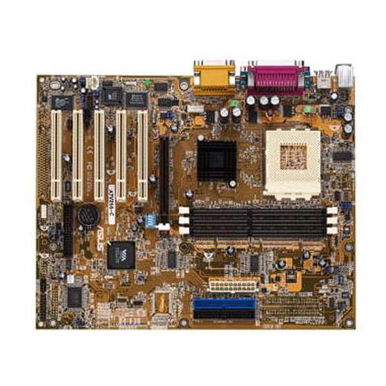
Page 11: Layout Of Via Kt266A Chipset Motherboard
HARDWARE INSTALLATION 2.2 Layout of VIA KT266A Chipset Motherboard K B M O U S E P S / 2 J P 5 T : M o u s e B:Keyboard M E M - L E D U S B P G A 4 6 2 T : T o p T : U S B 2... -
Page 12: Hardware Installation
HARDWARE INSTALLATION 2.3 CPU (Central Processing Unit) Installation All this point you should be familiar with the handling precautions; checked that you have all of the necessary hardware for building your system; inspected the motherboard package contents and, looked at the layout of the motherboard. This chapter will take you step-by-step through the process of installing the different hardware devices onto your new motherboard. -
Page 13: Cpu Installation
HARDWARE INSTALLATION fan, no force is required to insert the CPU into the socket. Once completely inserted, close the socket’s lever while holding down the CPU. This locks the CPU into the socket. Step 2: Connect the CPU fan’s cable to the CPU-FAN connector indicated on the diagram below. Ensure that the cable is connected correctly! It will be obvious which way it must fit. -
Page 14: 100/133Mhz System Configuration
HARDWARE INSTALLATION 2.4 100/133 MHz System Configuration SW3 allows you to set the FSB (Front Side Bus) for 100 or 133MHz Configuration. Please leave the SW3 setting as “133” if you want to adjust the FSB Clock from BIOS. (Please refer Section 3.10 Frequency/Voltage Control on page 46). -
Page 15: Suspend To Ram Setting
HARDWARE INSTALLATION 2.6 Suspend To RAM Setting (3-Pin JP4) To use the STR Function, turn off system power and short pin 2 and 3 of JP4. Reboot the system and enter BIOS Setup to turn on STR. Please left the Jumper setting at “STR_OFF”, then you can select the ACPI Suspend Type only through BIOS Menu. -
Page 16: Memory Configuration
HARDWARE INSTALLATION 2.8 Memory Configuration This motherboard must be installed with DIMMs (Dual Inline Memory Modules). The DIMMs must be 2.5V DDR DRAM modules. The VIA KT266 chipset supports PC1600 and PC2100 DDR DIMMs. You can install memory in any combination as follows: DIMM Location 184pin DIMM DIMM1... -
Page 17: Primary/Secondary Ide Connectors
HARDWARE INSTALLATION 2.9 Primary/Secondary IDE Connectors (Two 40-pin IDE) This motherboard supports two 40-pin IDE connectors marked as IDE1 (primary IDE channel) and IDE2 (secondary IDE channel). Each channel supports two IDE devices, for a total of four devices. Connect your Hard Disk Drive (HDD) (the main one if you are using more than one) to the “Master”... -
Page 18: Floppy Disk Drive Connector
HARDWARE INSTALLATION 2.10 Floppy Disk Drive Connector (34-pin FDC) This connector supports the provided floppy disk drive ribbon cable. After connecting the single plug end of this cable to the motherboard, connect the two plugs on the other end to the floppy disk drive(s). -
Page 19: Wake-On-Lan Connector
HARDWARE INSTALLATION 2.12 Wake-on-LAN Connector (3-pin WOL) This connector connects to LAN cards with a Wake-on-LAN output. The system can be powered up when a wakeup packet or signal is received from the LAN card. NOTE: This function requires the “Ring/WOL Resume” function in Power Management Setup-IRQ/Event Activity Detect to be “Enabled”... -
Page 20: Irda-Compliant Infrared Module Connector
HARDWARE INSTALLATION 2.14 IrDA-Compliant Infrared Module Connector (10-pin IrDA) The IrDA connector can be configured to support a wireless infrared module. With this module and application software such as Laplink or Win95 Direct Cable Connection, the user can transfer files to or from laptops (notebooks), PDAs, and printers. You must also configure the setting through “UART Mode Select”... -
Page 21: Panel Connectors
HARDWARE INSTALLATION 2.16 Panel Connectors PIN1 PIN11 P W _ L E D H D _ L E D EXT SMI R S T S P E A K E R P W R _ B T N PIN10 PIN20 Panel Connectors HDD_ LED (2-pin HD_LED) This 2-pin connector connects to the LED of the HDD. -
Page 22: Internal Audio Connectors
HARDWARE INSTALLATION Power LED (3-pin PW_ LED) This 3-pin connector attaches to the power LED. PIN11: +5V PIN12: NC PIN13: GND Speaker (4-pin SPEAKER) This 4-pin connector connects to the case-mounted speaker. PIN17: +5V PIN18: NC PIN19: NC PIN20: SPK 2.17 Internal Audio Connectors These connectors allow you to receive stereo audio input from sound sources such as a CD- ROM, TV tuner, or MPEG card. -
Page 23: External Back Panel I/O Ports
HARDWARE INSTALLATION 2.18 External Back Panel I/O Ports There are 9 kinds of external connectors on the motherboard. The view in the drawing is the back panel of the motherboard housing. PS/2 Mouse Port (Green 6-pin MOUSE) PS/2 Keyboard Port (Purple 6-pin KB) USB (Universal Serial Bus) Ports USB1 &... -
Page 24: Internal Usb Port Connectors
HARDWARE INSTALLATION 2.19 Internal USB Port Connectors (10-Pin JUSB1/2) You can use one or two optional serial port brackets to add two or four additional serial ports for additional serial devices. Regarding the external USB ports (USB1 and USB2), please refer to Section 2.18 “External Back Panel I/O Ports”. -
Page 25: Chapter 3 Bios Setup
BIOS SETUP CHAPTER 3 BIOS SETUP 3.1 BIOS Setup Award BIOS has a built-in Setup program that allows users to modify the basic system configuration. This information is stored in CMOS RAM, so it can retain the Setup information when the power is turned off. If the CMOS battery fails, these data will be lost. If that happens, you must setup your configuration parameters again after replacing the battery. - Page 26 BIOS SETUP Increase the numeric value or make changes Decrease the numeric value or make changes [F1] General help on Setup navigation keys [F5] Load previous values from CMOS [F6] Load the Fail-Safe Defaults from the BIOS default table [F7] Load the Optimized Defaults [F10] Save all the CMOS changes, and exit...
-
Page 27: Standard Cmos Features
BIOS SETUP Set Supervisor/User Password To change, set, or disable a password Save & Exit Setup To save settings in nonvolatile CMOS RAM and exit Setup Exit Without Saving To abandon all changes and exit Setup 3.3 Standard CMOS Features Date (mm:dd:yy)/Time (hh:mm:ss) Highlight the items and use [PageUp]/[PageDown] to change the value of Date/Time. - Page 28 BIOS SETUP IDE HDD Auto-Detection: Detect the HDD on this channel. If the detection is successful, the remaining fields on this menu are automatically filled in. IDE Primary/Secondary Master/Slave: We recommend that you select “AUTO” for all drives. The BIOS can automatically detect the specifications during POST (Power On Self Test) while the system boots.
- Page 29 BIOS SETUP Video Select the type of primary video subsystem in your computer. The BIOS will detect the correct video type automatically. EGA/VGA: Enhanced Graphics Adapter/Video Graphics Array. For EGA, VGA, SEGA, SVGA, or PGA monitor adapters. CGA 40: Color Graphics Adapter, powers up in 40-column mode. CGA 80: Color Graphics Adapter, powers up in 80-column mode.
-
Page 30: Advanced Bios Features
BIOS SETUP 3.4 Advanced BIOS Features The “Advanced BIOS Features” option allows you to improve your system performance, and setup system features according to your preferences. Virus Warning When this function is “Enabled”, you will receive a warning message if a program (specifically, a virus) attempts to write to the boot sector or the partition table of the hard disk drive. - Page 31 BIOS SETUP CPU L2 Cache ECC Checking Select “Enabled” to ensure that the data are accurate. Processor Number Feature This function was designed with the internet in mind. Select “ Enabled” to make the processor serial number serve as a means of identifying your system. Quick Power On Self Test Select “Enabled”...
-
Page 32: Gate A20 Option
BIOS SETUP Gate A20 Option Choose “Fast” (default) or “Normal”. “Fast” allows RAM access above 1MB to use the fast Gate A20 line. Typematic Rate Setting When this function is “Disabled”, the following two items (Typematic Rate and Typematic Delay) are irrelevant, and keystrokes repeat at a rate determined by the keyboard controller in your system. -
Page 33: Advanced Chipset Features
BIOS SETUP 3.5 Advanced Chipset Features This option will change the values of the chipset registers and the system settings will alter. Do not change any values if you are unfamiliar with the chipset. DRAM Clock/Drive Control This submenu allows you to adjust DRAM timing for stability or overclocking. Current FSB Frequency This field will display the current Front Side Bus (FSB) frequency. -
Page 34: Dram Clock
BIOS SETUP DRAM Clock You can select “By SPD” and let BIOS detect the DRAM Clock automatically. You can also set this field to “200MHz” or “266MHz”. The Default value is “By SPD”. DRAM Timing This item allows you to configure the next five BIOS items manually. If you aren’t familiar with these features, just leave this field as “By SPD”... - Page 35 BIOS SETUP DRAM Page-Mode Select “Enabled” to enhance DRAM performance. DRAM Drive Strength Selecting “Manual” instead of “Auto” allows you to set the DRAM Drive Value. DRAM Drive Value The field allows you to adjust the DRAM diving force (from 0000~00FF). DRAM Command Rate You can select “1T Command”...
- Page 36 BIOS SETUP AGP Driving Control This function allows you to adjust the AGP driving force. Choosing ‘Manual’ allows you set the AGP Driving Value in the next field. We recommend that you set this field to “Auto” to avoid any errors in system settings. AGP Driving Value This field allows you to adjust the AGP driving force (from 0000~00FF).
- Page 37 BIOS SETUP PCI 1/2 Post Write When “Enabled”, writes to the PCI devices are posted in the buffers. PCI Delay Transaction The chipset has an embedded 32-bit posted write buffer to support delay transaction cycles. Selecting “Enabled” supports compliance with PCI specification version 2.1. Memory Hole Enabling this feature reserves memory address space (between 15 and 16MB) to ISA expansion cards that specifically require this setting.
-
Page 38: Integrated Peripherals
BIOS SETUP 3.6 Integrated Peripherals Choose this option and the following display appears: VIA OnChip IDE Device This submenu configures the OnChip IDE controller. - Page 39 BIOS SETUP OnChip IDE Channel0/1 The chipset contains a PCI IDE interface which supports two IDE channels. Select “Enabled” to activate the first and/or second IDE interface. Select “Disabled” to deactivate this interface if you install a primary and/or secondary add-in IDE interface. IDE Prefetch Mode The Onboard IDE drive interface supports IDE prefetching for faster drive access.
- Page 40 BIOS SETUP VIA-3058 AC97 Audio Select “Auto” to enable the OnChip Audio Controller, which lets you use Onboard CODEC. If you use a PCI add-on Audio Card with an Audio Controller built-in, please set this field to “Disabled”. VIA Super IO Device This submenu allows you to configure various input/output devices.
- Page 41 BIOS SETUP IR Transmission Delay Consult your IR peripheral’s documentation to set this field. Options are: “Enabled” and “Disabled”. UR2 Duplex Mode Consult your IR peripheral’s documentation to select the proper setting for your IR device. Options are: “Full” and “Half”. Use IR Pins Consult your IR peripheral’s documentation to set this field.
- Page 42 BIOS SETUP Init Display First This item allows you to select which to activate first depending on the location of your video card: “PCI Slot” or “AGP”. OnChip USB Controller The VIA 8233 South Bridge has 3 USB Controllers. One of them is for the external USB ports (USB1 and USB2).
-
Page 43: Power Management Setup
BIOS SETUP 3.7 Power Management Setup Power Management Setup allows you to configure your system to minimize energy consumption according to your own style of computer use and preferences. ACPI Function The Advanced Configuration and Power Interface (ACPI) can be “Enabled” or “Disabled” with this item. - Page 44 BIOS SETUP There are three selections for the Power Management Option. Two of them have fixed Suspend Mode settings. 1. “Min Saving”: Minimum power management mode. Inactivity period is defined as 1 hour, at which point the system goes into Suspend Mode. 2.
- Page 45 BIOS SETUP State After Power Failure On: After a power failure, the system will automatically reboot as soon as power is restored. Off: After a power failure, the system will not reboot when power is restored. The system needs to be turned on again manually. Auto: After a power failure, the system will automatically reboot as soon as power is restored if the PC was turned on when the power failed.
- Page 46 BIOS SETUP Ring/WOL Resume Select “Enabled” to Power On your system when the external modem receives a call or when a LAN card receives a wake-up packet or signal. NOTE: This function requires a modem or an add-on LAN device, which supports the Ring Wake-Up or Wake-on-LAN (WOL) function, respectively.
-
Page 47: Pnp Os Installed
BIOS SETUP 3.8 PnP/PCI Configurations PnP OS Installed This field allows you to use a Plug and Play (PnP) operating system to configure the PCI bus slots instead of using the BIOS. Thus, interrupts may be re-assigned by the OS when “Yes”... - Page 48 BIOS SETUP IRQ Resources “IRQ-n Assigned to” When the resources are controlled manually, assign each system interrupt to one of the following, depending on which type of device is using the interrupt. PCI Device: PCI/ISA PnP devices, whether designed for PCI or ISA bus architecture, compliant with the Plug and Play standard.
-
Page 49: Pc Health Status
BIOS SETUP 3.9 PC Health Status This menu provides two thermo-protection functions (CPU warning temperature and shutdown temperature) and a hardware monitoring center. These features let you know the health status of your PC. CPU Warning Temperature This field allows you to set the CPU warning temperature. You can choose from “50°C/ 122°F”... -
Page 50: Frequency/Voltage Control
BIOS SETUP 3.10 Frequency/Voltage Control CPU Clock Ratio This function allows you to set the CPU internal frequency ratio. It determines the CPU internal frequency according to the following formula: CPU internal frequency = frequency ratio x system bus frequency.* NOTE: Because AMD has locked the frequency ratio for new CPU settings, this field to adjust the frequency ratio is usually useless. -
Page 51: Load Fail-Safe Defaults
BIOS SETUP CPU Clock This field allows you to set the CPU Clock Frequency from a minimum of “100” to a maximum of “132” if the FSB (Front Side Bus) is 100MHz. If the FSB is 133MHz, you can set this field from “133” to “166”. FSB Clock This field allows you to change the system FSB (Front Side Bus) Clock. -
Page 52: Load Optimized Defaults
BIOS SETUP 3.12 Load Optimized Defaults This option allows you to load the default values to the system configuration fields. These default values are the optimized configuration settings for the system. 3.13 Supervisor Password This option allows you to set a password to prevent others from changing the BIOS settings of your system. -
Page 53: User Password
BIOS SETUP At the prompt, type your password. Your password can be up to 8 alphanumeric characters. When you type the characters, they appear as asterisks on the password screen box. After typing the password, press the [Enter] key. At the next prompt, re-type your password and press the [Enter] key again to confirm the new password. -
Page 54: Save & Exit Setup
BIOS SETUP 3.15 Save & Exit Setup Save the settings and exit the BIOS utility. 3.16 Exit Without Saving Abort the current changes and exit the BIOS utility. -
Page 55: Chapter 4 Bios Upgrade
BIOS UPGRADE CHAPTER 4 BIOS UPGRADE Caution! Only users familiar with the upgrade procedure are recommended to update the BIOS of the motherboard and only when there is a need to do so. Please note that you have to download and install the right file for your motherboard. Otherwise, you might cause some serious system malfunctions. -
Page 56: Bios Upgrade
BIOS UPGRADE Step 3: Download the updated BIOS EXE file from the web site to a floppy disk or other storage device. Step 4: Execute the downloaded file to decompress it. Step 5: Please read the Readme.TXT file carefully, and follow the instructions step-by-step. Continue upgrading BIOS and reconfigure your system.
Need help?
Do you have a question about the VIA KT266A ChipsetMotherboard and is the answer not in the manual?
Questions and answers